1
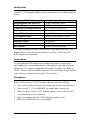
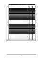
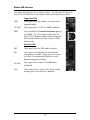
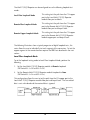
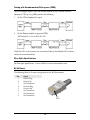
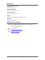
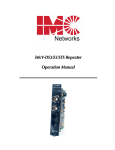
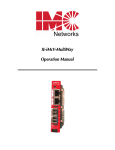
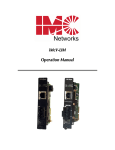
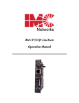
iMcV-T1/E1/J1 Repeater
Operation Manual
FCC Radio Frequency Interference Statement
This equipment has been tested and found to comply with the limits for a Class A computing device, pursuant to Part 15 of the FCC Rules.
These limits are designed to provide reasonable protection against harmful interference when the equipment is operated in a commercial
environment. This equipment generates, uses and can radiate radio frequency energy and, if not installed and used in accordance with the
instruction manual, may cause harmful interference to radio communications. Operation of this equipment in a residential area is likely to
cause harmful interference in which the user will be required to correct the interference at his own expense.
Any changes or modifications not expressly approved by the manufacturer could void the user’s authority to operate the equipment.
The use of non-shielded I/O cables may not guarantee compliance with FCC RFI limits. This digital apparatus does not exceed the Class A
limits for radio noise emission from digital apparatus set out in the Radio Interference Regulation of the Canadian Department of
Communications.
Le présent appareil numérique n’émet pas de bruits radioélectriques dépassant les limites applicables aux appareils numériques de classe A
prescrites dans le Règlement sur le brouillage radioélectrique publié par le ministère des Communications du Canada.
Warranty
IMC Networks warrants to the original end-user purchaser that this product, EXCLUSIVE OF SOFTWARE, shall be free
from defects in materials and workmanship under normal and proper use in accordance with IMC Networks' instructions
and directions for a period of six (6) years after the original date of purchase. This warranty is subject to the limitations set
forth below.
At its option, IMC Networks will repair or replace at no charge the product which proves to be defective within such
warranty period. This limited warranty shall not apply if the IMC Networks product has been damaged by unreasonable
use, accident, negligence, service or modification by anyone other than an authorized IMC Networks Service Technician
or by any other causes unrelated to defective materials or workmanship. Any replaced or repaired products or parts carry
a ninety (90) day warranty or the remainder of the initial warranty period, whichever is longer.
To receive in-warranty service, the defective product must be received at IMC Networks no later than the end of the
warranty period. The product must be accompanied by proof of purchase, satisfactory to IMC Networks, denoting
product serial number and purchase date, a written description of the defect and a Return Merchandise Authorization
(RMA) number issued by IMC Networks. No products will be accepted by IMC Networks which do not have an RMA
number. For an RMA number, contact IMC Networks at PHONE: (800) 624-1070 (in the U.S and Canada) or (949) 4653000 or FAX: (949) 465-3020. The end-user shall return the defective product to IMC Networks, freight, customs and
handling charges prepaid. End-user agrees to accept all liability for loss of or damages to the returned product during
shipment. IMC Networks shall repair or replace the returned product, at its option, and return the repaired or new
product to the end-user, freight prepaid, via method to be determined by IMC Networks. IMC Networks shall not be
liable for any costs of procurement of substitute goods, loss of profits, or any incidental, consequential, and/or special
damages of any kind resulting from a breach of any applicable express or implied warranty, breach of any obligation
arising from breach of warranty, or otherwise with respect to the manufacture and sale of any IMC Networks product,
whether or not IMC Networks has been advised of the possibility of such loss or damage.
EXCEPT FOR THE EXPRESS WARRANTY SET FORTH ABOVE, IMC NETWORKS MAKES NO OTHER WARRANTIES,
WHETHER EXPRESS OR IMPLIED, WITH RESPECT TO THIS IMC NETWORKS PRODUCT, INCLUDING WITHOUT
LIMITATION ANY SOFTWARE ASSOCIATED OR INCLUDED. IMC NETWORKS SHALL DISREGARD AND NOT BE
BOUND BY ANY REPRESENTATIONS OR WARRANTIES MADE BY ANY OTHER PERSON, INCLUDING EMPLOYEES,
DISTRIBUTORS, RESELLERS OR DEALERS OF IMC NETWORKS, WHICH ARE
INCONSISTENT WITH THE WARRANTY SET FORTH ABOVE. ALL IMPLIED WARRANTIES INCLUDING THOSE OF
MERCHANTABILITY AND FITNESS FOR A PARTICULAR PURPOSE ARE HEREBY LIMITED TO THE DURATION OF THE
EXPRESS WARRANTY STATED ABOVE.
Every reasonable effort has been made to ensure that IMC Networks product manuals and promotional materials
accurately describe IMC Networks product specifications and capabilities at the time of publication. However, because of
ongoing improvements and updating of IMC Networks products, IMC Networks cannot guarantee the accuracy of printed
materials after the date of publication and disclaims liability for changes, errors or omissions.
ii
Table of Contents
FCC Radio Frequency Interference Statement ....................................................ii
Warranty............................................................................................................ii
About the iMcV-T1/E1/J1 Repeater.....................................................................4
Installation .........................................................................................................4
Configuration .....................................................................................................5
Prerequisites ......................................................................................................5
Description of DIP Switch-Selectable Options ....................................................7
Module LED Functions.....................................................................................12
Testing .............................................................................................................13
Fiber Optic Specifications.................................................................................16
RJ-48 Pinout ....................................................................................................16
Specifications ...................................................................................................17
IMC Networks Technical Support.....................................................................17
Fiber Optic Cleaning Guidelines.......................................................................18
Electrostatic Discharge Precautions...................................................................18
Safety Certifications..........................................................................................19
iii
About the iMcV-T1/E1/J1 Repeater
The iMcV-T1/E1/J1 Repeater chassis mounted media conversion module allows the
end user to extend the distances between T1, J1, and E1 copper telephony systems
by adding a fiber segment. The distances can support up to 100km depending on
the module used and the fiber type available.
Installation
At the central location the iMcV-T1/E1/J1 Repeater unit is typically installed in a
managed chassis such as the iMediaChassis or the MediaChassis series.
NOTES
Chassis are also available in Industrial Ethernet (IE) configurations.
It is not recommended that the iMcV-T1/E1/J1 module be installed in an 850-33100. The
power source in this chassis is not isolated, and cannot support positive reference ground
systems typically used in Telco environments.
The MediaChassis/2-DC and the iMediaChassis/6-DC are suitable alternatives.
Each module requires one slot in the chassis. To install a module, remove the blank
brackets covering the slots where the module is to be installed (if present) by
removing the screws on the outside edges of the bracket. Slide the module into the
chassis, via the card guides, until the module is seated securely in the connector.
Secure the module to the chassis by tightening the captive screw. Save any “blanks”
removed during installation for future use should the configuration requirements
change.
Crossover/Straight-Through Connection
iMcV-T1/E1/J1 Repeater comes with an RJ-48 UTP connector that features a pushbutton switch, located next to the port, for selecting a crossover or straight-through
connection. To select a cross-over connection, press the push-button IN. A straightthrough connection is selected when the push-button is OUT. When unsure what
type of connection is needed, set the push button to the position that turns the NO
LNK LED off.
4
Configuration
The iMcV-T1/E1/J1 Repeater module is factory-configured to use the following default
features:
T1/E1 Mode
Receive Equalizer Gain Limit (EGL)
Line Encoding
Transmit LIU Waveshape (Build-out)
Receive LIU Termination
Transmit Data Source
Jitter Attenuator Select
Remote Management
Loopback Selection
Monitor/Boost Mode
NRZ Selection
T1
-30 dB (Limited Long Haul)
AMI (Passive Mode)
DSX-1 (0 to 133 ft) 0 dB CSU
Receive Side 100 ohms Enabled
Standard Data
Place Jitter Attenuator on TX Side
Remote Management Disabled
No Loopback
No Boost
Disable NRZ (Passive Mode)
The iView2 management software can be used to change some of the iMcV-T1/E1/J1
Repeater features after installing the modules in the chassis. Refer to the iView2
online help for more information.
Passive Mode
It is recommended that the default Passive mode configuration is used for most
typical applications. Passive mode allows the fiber segment to pass data unchanged
between the T1/E1 segments independent of the actual line coding (AMI, B8ZS, or
HDB3). All errors and fault conditions from one T1/E1 end will pass through the fiber
to the other end as if there were one long T1/E1 connection.
Prerequisites
Before installing the iMcV-T1/E1/J1 Repeater modules, perform the following:
•
•
•
•
•
Make sure the modules are correct for the fiber type and distance requirements.
Make sure that T1 UTP lines DO NOT use simplex power (no wet lines).
Before installing the iMcV-T1/E1/J1 Repeater modules, verify the DIP Switches
are configured for the feature wanted.
Make sure to deploy the iMcV-T1/E1/J1 Repeater modules in pairs.
Make sure the Remote Chassis is not managed.
5
NOTE
The iMcV-T1/E1/J1 Repeater modules are delivered pre-configured for standard T1
operation in Passive mode. To enable remote management, the user must move DIP
Switch S2-2 to the “ON” position on the Remote module (refer to the DIP Switch diagram
and table).
Managed Modules
To manage iMcV-T1/E1/J1 Repeater modules, an SNMP agent must be present; the
iMediaChassis requires an SNMP management module. For a managed
environment, first manually configure all of the desired DIP Switch selectable features
to match what will be configured through the SNMP Management Module.
Use the Graphical User Interface (GUI) to enable features by using the iView2 SNMP
management software. In a managed chassis, the software settings take priority over
the SNMP enabled feature DIP Switch settings. Make sure that the software settings
match the desired configuration requirements for the installation.
iView² Management Software
iView² is the IMC Networks management software designed specifically for the IMC
Networks “iMcV” family of modules. It features a GUI and gives network managers
the ability to monitor and control the manageable IMC Networks products.
iView² is available in several versions and can also function as a snap-in module for
HP OpenView Network Node Manager and other third party SNMP Management
software. For assistance in selecting the right version of iView² for your operating
system, please visit:
http://www.imcnetworks.com/products/iview2.cfm
iView2 supports the following platforms:
•
•
•
•
Windows NT
Windows 2000
Windows XP
Windows Vista
In addition, there are Java versions of iView² for any Java-capable operating systems
such as Linux.
Please see the SNMP Management Module for software configuration options.
NOTE
IMC Networks’ iView2 software is available for downloading from the web site:
www.imcnetworks.com.
6
Unmanaged Modules
Before installing the iMcV-T1/E1/J1 Repeater module into an unmanaged chassis,
configure the module hardware-selectable features via DIP Switches located at
position S3 and S2 on the PCB (refer to the DIP Switch Table section for more
information). The jumpers located at positions JP1 and JP2 are factory configured—
DO NOT CHANGE.
Description of DIP Switch-Selectable Options
The iMcV-T1/E1/J1 Repeater module includes movable DIP Switches for hard
switching the optional features. Some of these switch options are overridden by the
management setting of a managed chassis (refer to the DIP Switch Table section for a
list of the iView2 managed switches).
This module is shipped in the standard T1 option configuration. The following
section contains a brief description of the available options.
T1/E1/J1 Mode
This option allows the user to select the data rate standard that the module will use
when converting: T1/J1 (default) or E1. The default is OFF, T1/J1 mode selected.
Receive Equalizer Gain Limit (EGL)
This option allows the user to compensate for diminishing signal intensity over the
data line by adjusting the sensitivity of the UTP receiver. By setting the Receive
Equalizer Gain Limit, very long copper lines can be utilized.
Line Encoding
This option allows the user to set the transmit/receive encoding for HDB3, B8ZS or
AMI (default).
NOTE
There are currently no applications that use any other settings than AMI encoding and
NRZ disabled (Passive mode). Changing the encoding setting to anything other than AMI
can result in data corruption.
Transmit LIU Waveshape (Line Build-out)
This option allows the user to control the waveshape being output by the transmitter.
This helps to correct problems related to long cables. Improperly setting this switch
will cause signal degradation.
7
Receive LIU Termination (Line Termination)
This option allows the user to set the receive termination. This is used to properly
terminate cables in order to prevent signal reflections which can cause signal
degradation.
Transmit Data Source
This option allows the user to set the module to send normal data (default) or to send
specific test-patterns of data to determine problems along the cable as a diagnostic
tool. The user can set the module to send a PRBS (215-1 for E1 and 220-1 for T1), an
alternating ones and zeros, or an unframed all ones code, depending on the
diagnostic requirements.
Jitter Attenuator Select
This option allows the user to select Jitter Attenuation on the UTP transmit or receive
side. This decreases jitter in the data stream which increases data reliability.
NOTE
The jitter attenuator must always be enabled on the transmit side of the copper line.
Loopback Selection
This option allows the user to set the Loopback location on the module. Loopback is
a diagnostic tool that enables the user to test the integrity of the line by allowing the
data to be looped back. The following independent loopback locations are included
on the module:
Analog Loopback
Set this switch on the Remote module to loop the data back
from the remote copper port (refer to the Remote Copper
Loopback Mode section for more information).
Local Loopback
Set this switch on the Remote module to loop the data back
from the remote fiber port (refer to the Remote Fiber Loopback
Mode section for more information).
Remote
Loopback
Set this switch on the local module to loop the data back from
the local fiber port (refer to the Local Fiber Loopback Mode
section for more information).
Refer to the Loopback Testing section for application examples of the loopback testing
modes.
8
Remote Management
This option allows the user to enable Remote management on the module. The
remote management feature is designed to work only on the remote module of
the Local/Remote pair. With Remote management enabled, the user can easily
perform the following:
•
Test the line integrity of the remote copper port.
•
Use the Local unit to configure all SNMP-configurable features for both units.
•
Use the Local unit to download firmware for both units.
Refer to the Module LED Functions section for more information.
NOTE
When the user enables the Remote management feature on the remote module, it is
necessary to disable SNMP-management on the chassis in which the remote unit is
installed (i.e. turn the iMediaChassis enter chassis SNMP switch off, or do not install an
SNMP Management module in either an iMediaChassis or iMcV series chassis.
Monitor/Boost Mode
This option allows the user to boost the UTP receive signal (i.e internal linear gain
boost). This helps the UTP receiver to compensate for line loss.
NRZ (Non-Return-to-Zero)
This option allows the user to enable or disable the NRZ mode.
NOTE
There are currently no applications that use any other settings than AMI encoding and
NRZ disabled (Passive mode). Enabling NRZ can result in data corruption.
Enabling NRZ terminates the line coding on the copper line. This forces the module
to send raw data to the fiber line without line code information.
9
Switch Settings for Switch S2
T1/E1 Selection
S2-1: OFF
S2-1: ON
T1 Mode Selected
E1 Mode Selected
default
Receive Equalizer Gain Limit (EGL)
iVIEW2
iVIEW2
iVIEW2
iVIEW2
iVIEW2
iVIEW2
E1
S2-2: ON -12 dB (Short Haul)
S2-2: OFF -43 dB (Long Haul)
T1
S2-2: ON -36 dB (Long Haul)
S2-2: OFF -30 dB (Limited Long Haul)
default
iVIEW2
Line Encoding iVIEW2
S2-3: ON HDB3 (E1) / B8ZS (T1)
S2-3: OFF AMI (Required for Passive Mode)
iVIEW2
iVIEW2
default
Transmit LIU Waveshape (Build-out)
SWITCH S2
E1
S2-4: ON
S2-4: OFF
S2-4: ON
S2-4: OFF
S2-5: ON
S2-5: ON
S2-5: ON
S2-5: ON
S2-6: ON
S2-6: ON
S2-6: OFF
S2-6: OFF
75 ohms
125 ohms
75 S ohms w/ High Return Loss
125 S ohms w/ High Return Loss
S2-4: ON
S2-4: OFF
S2-4: ON
S2-4: OFF
S2-4: ON
S2-4: OFF
S2-4: ON
S2-4: OFF
S2-5: ON
S2-5: ON
S2-5: OFF
S2-5: OFF
S2-5: ON
S2-5: ON
S2-5: OFF
S2-5: OFF
S2-6: ON
S2-6: ON
S2-6: ON
S2-6: ON
S2-6: OFF
S2-6: OFF
S2-6: OFF
S2-6: OFF
DSX-1 (0 to 133 ft) 0 dB CSU
DSX-1 (133 to 266 ft)
DSX-1 (266 to 399 ft)
DSX-1 (399 to 533 ft)
DSX-1 (533 to 655 ft)
-7.5 dB CSU
-15 dB CSU
-22.5 dB CSU
T1
default
Receive LIU Termination
S2-7: ON
S2-7: OFF
S2-7: ON
S2-7: OFF
S2-8: ON
S2-8: ON
S2-8: OFF
S2-8: OFF
Receive Side Termination Disabled
Receive Side 120 ohms Enabled
Receive Side 100 ohms Enabled
Receive Side 75 ohms Enabled
default
Transmit Data Source iVIEW2
S2-9: ON
S2-9: OFF
S2-9: ON
S2-9: OFF
S2-10: ON
S2-10: ON
S2-10: OFF
S2-10: OFF
Standard Data
Transmit Pseudorandom Bit Sequence (PRBS)
Transmit Alternating Ones and Zeros
Transmit Unframed All Ones
10
iVIEW2
iVIEW2
iVIEW2
iVIEW2
default
Switch Settings for Switch S3
Jitter Attenuator Select
S3-1: ON
S3-1: OFF
Place Jitter Attenuator on RCV Side
Place Jitter Attenuator on XMT Side
default
Remote Management
S3-2: ON
S3-2: OFF
Remote Management Enabled (only at the REMOTE end)
Remote Management Disabled (only at the LOCAL end)
default
SWITCH S3
Loopback Selection iVIEW2
S3-3: ON
S3-3: OFF
S3-3: ON
S3-3: OFF
S3-4: ON
S3-4: ON
S3-4: OFF
S3-4: OFF
None
Local Loopback
Analog Loopback
Remote Loopback
iVIEW2
iVIEW2
iVIEW2
iVIEW2
default
Monitor/Boost Mode
S3-5: ON
S3-5: OFF
S3-5: ON
S3-5: OFF
S3-6: ON
S3-6 ON
S3-6 OFF
S3-6 OFF
Normal Operation (No Boost)
20 dB
26 dB
32 dB
default
NRZ Selection iVIEW2
S3-7: ON
S3-7: OFF
Disable NRZ (Required for Passive Mode)
Enable NRZ (Line Terminating Mode)
iVIEW2
iVIEW2
Fiber Type
S3-8: Factory Configured
S3-9: Factory Configured
S3-10: Factory Configured
DO NOT CHANGE
DO NOT CHANGE
DO NOT CHANGE
DIP Switch Table
All iView2 enabled switches are overridden by management software.
11
default
Module LED Functions
This section describes the LEDs and their functions. The Fiber port LED RM is the
only LED that should be lit on the modules under normal operating conditions.
Copper Port LEDs
LPBK
Glows green when the module is set to one of the
Loopback modes.
NO LNK
Glows green when a UTP link is NOT established.
PBEO
Only used when the Transmit Data Source option is
set to PRBS. This LED will glow amber when the
iMcV-T1/E1/J1 Repeater module receives errors and
will stay dark when the converter receives a PRBS
without errors.
Fiber Port LEDs
NRZ
Glows green when the NRZ mode is enabled.
RM
Glows green on the Remote unit when Remote
management is enabled. Glows green on the Local
unit when it has discovered a Remote unit with
Remote management enabled.
NO LNK
Glows green when a fiber link has NOT been
established.
SYM
Glows amber when a 4-bit to 5-bit (4b/5b) symbol
encoding error in the fiber line is detected.
12
Testing
To test a media converter by itself, first make sure there is an appropriate fiber patch
cable, then perform the following steps:
1.
Connect the media converter to the T1/E1 device with a standard UTP cable. If
the NO LNK LED for the copper port remains on, a valid signal is not being
received. Push the crossover push button on the front of the unit. Verify that
the NO LNK LED for the copper port is off.
2.
Loop a single strand of fiber from the transmit port to the receive port of the
media converter. Verify that the NO LNK LED for the fiber port is off.
Or
For single-strand fiber products, connect a single fiber cable from the Local
iMcV-T1/E1/J1 Repeater to the remote iMcV-T1/E1/J1 Repeater. Verify that the
NO LNK LED for the fiber port is off.
Loopback Testing
The iMcV-T1/E1/J1 Repeater includes the following loopback locations:
•
•
•
Local
Remote
Analog
Local Loopback
The Local loopback location on the module loops
the fiber-receive port to the fiber-transmit port.
Remote Loopback
The Remote loopback location on the module
loops the fiber-transmit port to the fiber-receive
port.
Analog Loopback
The Analog loopback location on the module
loops the copper-transmit port to the copperreceive port.
13
The iMcV-T1/E1/J1 Repeater can be configured to use the following loopback test
modes:
Local Fiber Loopback Mode
This setting tests the path from the CO copper
port to the Local iMcV-T1/E1/J1 Repeater
module fiber port and back.
Remote Fiber Loopback Mode
This setting tests the path from the CO copper
port to the Remote iMcV-T1/E1/J1 Repeater
module fiber port and loops it back.
Remote Copper Loopback Mode
This setting tests the path from the CO copper
port to the Remote iMcV-T1/E1/J1 Repeater
module copper port and loops it back.
The following illustrations show a typical progression of digital loopback tests; this
series allows the user to individually test each segment of the conversion. To test the
copper segment at the remote location requires the PRBS test described in the next
section.
Local Fiber Loopback Mode
To set the loopback testing mode to Local Fiber Loopback Mode, perform the
following:
1.
Set the Local iMcV-T1/E1/J1 Repeater module to Remote Loopback
(DIP Switch S3-3=Off and S3-4=Off)
2.
Set the Remote iMcV-T1/E1/J1 Repeater module Loopback to None
(DIP Switch S3-3=On and S3-4=On).
This configuration allows the user to test the path from the CO copper port to the
Local iMcV-T1/E1/J1 Repeater module fiber port and loop it back. The transmitted
data is sent unhindered and the received data is ignored.
14
Remote Fiber Loopback Mode
To set the loopback testing mode to Remote Fiber Loopback Mode, perform the
following:
1.
Set the Local iMcV-T1/E1/J1 Repeater module Loopback to None
(DIP Switch S3-3=On and S3-4=On)
2.
Set the Remote iMcV-T1/E1/J1 Repeater module to Local Loopback
(DIP Switch S3-3=Off and S3-4=On).
This configuration allows the user to test the path from the CO copper port to the
Remote iMcV-T1/E1/J1 Repeater module fiber port and loop it back. The transmitted
data is sent unhindered and the received data is ignored.
Remote Copper Loopback Mode
To set the loopback testing mode to Remote Copper Loopback Mode, perform the
following:
1.
Set the Local iMcV-T1/E1/J1 Repeater module Loopback to None
(DIP Switch S3-3=On and S3-4=On)
2.
Set the Remote iMcV-T1/E1/J1 Repeater module to Analog Loopback
(DIP Switch S3-3=On and S3-4=Off).
This configuration allows the user to test the path from the CO copper port to the
Remote iMcV-T1/E1/J1 Repeater module copper port and loop it back. The
transmitted data is sent unhindered and the received data is ignored.
After the user has confirmed the integrity of these data paths, the user can activate
the PRBS data generator on the Remote module and place a loopback on the
customer premise equipment to test the final copper segment (refer to the Testing
with PRBS section for more information).
15
Testing with Pseudorandom Bit Sequence (PRBS)
To test the copper segment from the Remote module to the Customer Premises
Equipment (CPE) by using PRBS, perform the following:
1.
Set the CPE to loopback the signal.
2.
Set the Remote module to generate PRBSs
(DIP Switch S2-9=On and S2-10=Off).
Check the LEDs to verify errors are not received (refer to the Module LED Functions
section for more information).
Fiber Optic Specifications
For fiber optic specifications, visit our Web site at www.imcnetworks.com.
RJ-48 Pinout
The following table lists the pin configuration for the RJ-48 connector.
Pin
1
2
3
4
5
6
7
8
Signal
Receive Ring
Receive Tip
No Connection
Transmit Ring
Transmit Tip
No Connection
No Connection
No Connection
PIN 1
16
Specifications
Power Consumption (Typical)
0.550 Amp @ 5V
Operating Temperature
+32°F to +122° F (0°C to +50° C)
Storage Temperature
-4°F to +158°F (-20°C to +70° C)
Humidity
5 to 95% (non-condensing); 0 to 10,000 ft. altitude
Dimensions
Single Slot iMcV-Module
IMC Networks Technical Support
Tel: (949) 465-3000 or (800) 624-1070 (in the U.S. and Canada);
+32-16-550880 (Europe)
Fax: (949) 465-3020
E-Mail: [email protected]
Web: www.imcnetworks.com
17
Fiber Optic Cleaning Guidelines
Fiber Optic transmitters and receivers are extremely susceptible to contamination by
particles of dirt or dust, which can obstruct the optic path and cause performance
degradation. Good system performance requires clean optics and connector ferrules.
1.
Use fiber patch cords (or connectors, if you terminate your own fiber) only from
a reputable supplier; low-quality components can cause many hard-to-diagnose
problems in an installation.
2.
Dust caps are installed at IMC Networks to ensure factory-clean optical devices.
These protective caps should not be removed until the moment of connecting
the fiber cable to the device. Should it be necessary to disconnect the fiber
device, reinstall the protective dust caps.
3.
Store spare caps in a dust-free environment such as a sealed plastic bag or box
so that when reinstalled they do not introduce any contamination to the optics.
4.
If you suspect that the optics have been contaminated, alternate between
blasting with clean, dry, compressed air and flushing with methanol to remove
particles of dirt.
Electrostatic Discharge Precautions
Electrostatic discharge (ESD) can cause damage to any product, add-in modules or
stand alone units, containing electronic components. Always observe the following
precautions when installing or handling these kinds of products
1.
Do not remove unit from its protective packaging until ready to install.
2.
Wear an ESD wrist grounding strap before handling any module or component.
If the wrist strap is not available, maintain grounded contact with the system unit
throughout any procedure requiring ESD protection.
3.
Hold the units by the edges; do not touch the electronic components or gold
connectors.
4.
After removal, always place the boards on a grounded, static-free surface, ESD
pad or in a proper ESD bag. Do not slide the modules or stand alone units over
any surface.
WARNING! Integrated circuits and fiber optic components are
extremely susceptible to electrostatic discharge damage. Do not
handle these components directly unless you are a qualified service
technician and use tools and techniques that conform to accepted
industry practices.
18
Safety Certifications
UL/CUL: Listed to Safety of Information Technology Equipment, including Electrical
Business Equipment.
CE: The products described herein comply with the Council Directive on
Electromagnetic Compatibility (2004/108/EC) and the Council Directive
on Electrical Equipment Designed for use within Certain Voltage Limits
(2006/95/EC). Conforms to UL Std. 60950-1; Certified to CSA Std.
C22.2 No. 60950-1
3178738
Class 1 Laser product, Luokan 1 Laserlaite,
Laser Klasse 1, Appareil A’Laser de Classe 1
European Directive 2002/96/EC (WEEE) requires that any equipment that bears this
symbol on product or packaging must not be disposed of with unsorted municipal
waste. This symbol indicates that the equipment should be disposed of separately
from regular household waste. It is the consumer’s responsibility to dispose of this
and all equipment so marked through designated collection facilities appointed by
government or local authorities. Following these steps through proper disposal and
recycling will help prevent potential negative consequences to the environment and
human health. For more detailed information about proper disposal, please contact
local authorities, waste disposal services, or the point of purchase for this equipment.
19
19772 Pauling • Foothill Ranch, CA 92610-2611 USA
TEL: (949) 465-3000 • FAX: (949) 465-3020
www.imcnetworks.com
© 2011 IMC Networks. All rights reserved
The information in this document is subject to change without notice. IMC Networks assumes no responsibility for any
errors that may appear in this document. iMcV-T1/E1/J1 is a trademark of IMC Networks. Other brands or product names
may be trademarks and are the property of their respective companies.
Document Number 50-80200-00 B2
March 2011