Transcript
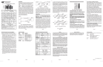
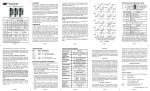
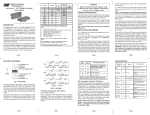
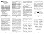
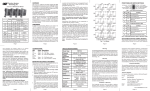
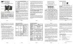
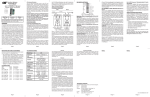
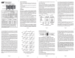
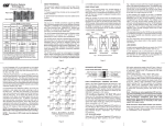
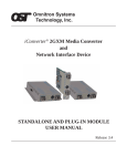
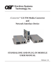
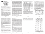
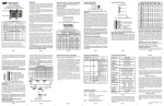
iConverter™ Redundant Fast Ethernet Module
User Manual
Port A
Port C
Port B
iConverter Tx/2Fx Dual Fiber Modules
Connector Type
Fiber
Type
Distance
ST
SC
MT-RJ
LC
MM
5km
8420-0
8422-0
8424-0
-
SM
30km
8421-1
8423-1
8425-1
8427-1
SM
60km
8421-2
8423-2
-
8427-2
SM
120km
-
8423-3
-
-
product family. The following models are described:
Tx/2Fx
100BASE-TX UTP to dual 100BASE-FX dual fiber
Tx/2Fx SF 100BASE-TX UTP to dual 100BASE-FX single-fiber
Tx/2Tx
100BASE-TX UTP to dual 100BASE-FX UTP
The iConverter Redundant Fast Ethernet modules are
intended for use in networks that require fiber or copper
link redundancy. During normal operations Port A is the
active primary and Port B is the backup secondary. When
loss of link on Port A is detected, the module automatically
switches to transmitting on Port B. With a switch over time
of less than 100 microseconds, these modules provide
the rapid response time required for ultra critical
applications. Note: After the link is switched, there will be
a 5 second delay before that link can been reestablished.
APPLICATION EXAMPLES:
iConverter Tx/2Fx SF Single-Fiber Modules
Fiber /
Connector
Type
Distance
SM / SC
20 km
8430-1
8431-1
SM / SC
40 km
8430-2
8432-2
Tx: 1310 nm,
Rx: 1550 nm
Tx: 1550 nm,
Rx: 1310 nm
iConverter Tx/2Tx
Distance
RJ-45 UTP Connector
Fig. 1 Redundant Switch Example
100m
8400-0
In this example, redundant Switches 1 and 2 are connected
to Switch 3 via a Tx/2Fx converter. If power fails in
Switch 1, or if there is a loss of link in the fiber cable, the
Tx/2Fx converter switches to transmitting on port B and
routes data flow to Switch 2.
Page 2
For wide temperature (-40 to 60º C), add a "W" to the end of the
model number. Consult factory for extended temperature
(-40 to +75º C) models.
When using single-fiber (SF) media converter models, the Tx wavelength on one end has to match the Rx wavelength on the other.
MOUNTING AND CABLE ATTACHMENT:
LED INDICATORS:
iConverter modules are hot-swappable and can be
installed into any chassis in the iConverter family.
1. Carefully slide the iConverter module into the
LED
Power:
Port A Link:
2.
3.
4.
5.
In “Remote Fault Detection” (RFD), the UTP port
transmits a “Link” signal only when receiving a “Link” at
both the fiber ports. The fiber port transmits a “Link”
only when receiving “Link” signals both at the fiber port
and the UTP port. As a result, fiber faults (no “Link”
received at the fiber) are looped-back and can be reported
to the network’s core (Not Shown).
OVERVIEW:
The iConverter Redundant Fast Ethernet manageable
media converters are members of the modular iConverter
installation slot, aligning the module with the
installation guides. NOTE: Ensure that module is
firmly seated against the backplane.
Secure the module by securing the panel fastener
screw (attached to module) to chassis front.
Attach the UTP port of Port C via a category 5 cable
to a 100BASE-TX Ethernet device.
iConverter Redundant Fast Ethernet Modules should
be deployed in pairs with Port A linked to Port A and
Port B linked to Port B between the two modules. If
using iConverter Redundant Fast Ethernet Modules
with redundant Fx or Fx SF ports, attach Port A fiber
ports and Port B fiber ports of the two modules via
an appropriate multimode or single-mode fiber cable.
The iConverter transmit (Tx) must attach to the
receive side on other device; the receive (Rx) must
attach to the transmit. If using iConverter Redundant
Fast Ethernet Modules with redundant Tx ports, attach
the UTP ports of the two modules’ Port A via a
category 5 cable and UTP ports of the two modules’
Port B via a category 5 cable.
Single fiber (SF) media converter models must be
deployed in pairs so that the transmission (Tx) and
reception (Rx) wavelengths of the single-mode (SM)
ports communicating over a fiber must match the
reception (Rx) and transmission (Tx) at the opposite
end. For example, an 8430-1 should be connected
to an 8431-1.
Color
Yellow
Green
Port B Link: Green
Port C Link: Green
Port A Select: Green
Port B Select: Green
UTP Auto:
UTP FDx:
Green
Green
Fig. 2 Redundant Fiber to Customer
In this example, data flow from a core switch at the
Central Office is converted from UTP to redundant
fiber, and converted back to UTP, where it is connected
to an edge switch at the Customer Premises. If there is
a loss of link in fiber Port A, the Tx/2Fx converter
switches to transmitting on fiber Port B, without a service
disruption to the mission-critical customer.
LINK MODES:
In order to accommodate different user needs, the
Redundant iConverters support four different linking modes.
NOTE that it is recommended keeping the
Redundant iConverters in the factory default Link
Segment (LS) setting.
In “Link Segment” (LS), sometimes referred to as the
“Normal” mode, a port transmits a “Link” signal
independently of any received “Link” at any other port.
For example, the UTP transmits a “Link” regardless of
either fiber receiving a “Link” [Fig 3(a) & (b)]. Figure 3(a)
shows the state when all links are functioning correctly.
Port A LEDs indicate link and activity, while the Port B
LEDs blink at one Hertz to indicate they are not active,
but are in “Standby”. Figure 3(b) shows that when the
fiber link to Port A is broken, Port B becomes active.
In “Link Propagate” (LP), sometimes referred to as “Link
Loss Carry Forward”, a port transmits a “Link” signal
only when receiving a “Link” at its other port. For
example, the UTP transmits a “Link” only when receiving
a “Link” at both fiber ports (Not Shown).
Page 3
REDUNDANT FIBER SPECIFICATIONS:
Description
On--Power
On--Link / Blink--activity
Steady Blink--Standby mode
On--Link / Blink--activity
Steady Blink--Standby mode
On--Link / Blink--activity
On--Active port / Blink--remote
side broken
On--Active port / Blink--remote
side broken
On--Auto-Negotiation enabled
On--Full-Duplex detected
In “Symmetrical Fault Detection” (SFD), the UTP port
transmits a “Link” signal only when receiving a “Link” at
both the fiber ports. The fiber port transmits a “Link” only
when receiving “Link” signal from both the fiber ports and
the UTP port. As a result, fiber faults (no “Link” received
at the fiber) are looped back and can be reported to the
network core. In addition, connecting two back-to-back
converters which are both set to SFD facilitates dualloop-back where fiber faults are reported to both ends of
the network (Not Shown).
Model Type
Tx/2Fx
Tx/2Tx
100BASE-FX,
100BASE-TX
100BASE-TX
Primary
Connectors
RJ-45
RJ-45
Redundant
Connectors
SC, ST, LC, MT-RJ,
Single-Fiber SC
RJ-45
Controls
UTP X-over, LS/LP,
RFD, SFD, UTP
Auto/Man, FDX/HDX
UTP X-over, LS/LP,
RFD, SFD, UTP
Auto/Man, FDX/HDX
Power, FO link,
UTP link, Select,
Auto, FDX/HDX
Power, UTP link,
UTP link, Select,
Auto, FDX/HDX
Protocols
LED Displays
Dimensions
W:0.85" x D:4.5" x H:2.8"
Weight
Compliance
8 oz.
UL, CE, FCC Class A
Power
Requirement
(typical)
0.7A @ 3.3VDC
Temperature
Standard:
Wide:
Storage:
Humidity
5 to 95% (non-condensing)
Altitude
-100m to 4000m
MTBF (hrs)
1.1A @ 3.3VDC
0 to 50º C
-40 to 60º C
-40 to 80º C
520, 000
BOARD MOUNTED DIP-SWITCH SETTINGS:
Fig. 4 Board Mounted DIP-Switches
Link Segment/Propagate “LS/LP” DIP-Switch:
This DIP-Switch enables the Link Segment “LS” or Link
Propagate “LP” modes. When in the “LS” position (left,
factory default), Link Segment mode is enabled. In the “LP”
or “ON” position (right), Link Propagate mode is enabled.
Note that for “LS” mode, “LP”, “RFD” and “SFD”,
DIP-Switches must be in the Left position (factory
setting).
Note that setting more than one of the mode switches
(“LP”, “RFD” or “SFD”) to the Right position on the
same module is an illegal mode that will result in
unpredictable behavior.
Remote Fault Detection “RFD” DIP-Switch:
When in the “RFD” position, the Remote Fault Detection
mode is enabled.
Note that connecting two converters with both set
to RFD mode is illegal and will cause a “deadly
embrace” lockup.
Fig. 3 Link Modes
Page 4
Warning
The operating description in this Instruction Manual is for use
by qualified personnel only. To avoid electrical shock, do not
perform any servicing of this unit other than that contained in
the operating instructions, unless you are qualified and certified
to do so by Omnitron Systems Technology, Inc.
UTP Auto/Manual “AN/MAN” DIP-Switch:
When this DIP-Switch is set to Auto Negotiate “AN”
(factory setting) it enables the UTP Port to determine
duplex mode automatically. If the connected device
cannot provide the proper signal to indicate its own
mode of operation, this DIP-Switch should be set to
Manual “MAN”. This feature allows connections with
devices that do not auto negotiate properly.
UTP Full/Half-Duplex “FD/HD” DIP-Switch:
When the UTP Auto/Manual DIP-Switch is in Manual
“MAN” position (described above), the UTP Full/HalfDuplex “FD/HD” DIP-Switch determines the duplex
operation mode for the UTP port. When set to FullDuplex “FD” (factory setting), the UTP port operates in
Full-Duplex. When set to Half- Duplex “HD” the UTP
port operates in Half-Duplex. Adjust the Half/Full-Duplex
DIP-Switch to match the connecting device and check
for link status.
Return to Port A “RTA/NR” DIP-Switch:
When this DIP-Switch is in the Return to Port A “RTA”
position (factory default), link reestablishment on Port
A immediately returns data transmission to Port A after
a link failure in the connection between the A ports.
Even though the switch over time is less than 100
milliseconds, there is the possibility of lost data (dropped
packet) when the Return to Port A “RTA” DIP-Switch
setting is selected. When the switch is set to Not
Return to A “NR”, Port B continues to be used for
transmitting data even after link has been reestablished
on Port A.
Note that modules connected together must be set to
the same mode for correct operation.
Symmetrical Fault Detection “SFD” DIP-Switch:
When this DIP-Switch is in the “SFD” position (right), the
Symmetrical Fault Detection mode is enabled. Note that
when a loss of “Link” occurs between two Redundant Fast
Ethernet modules, both redundant connections must have
a loss of incoming “Link” signal in order for this to occur.
RJ45 Crossover “= / X” Switch (Not Shown):
When connecting the UTP to a hub or switch, set switch to
Straight-Through “=” (factory setting). When connecting to a
workstation, set to Crossover “X”.
Page 5
Page 6
Exclusive Remedies
The remedies provided herein are the Buyer’s sole and
exclusive remedies. Omnitron shall not be liable for any
direct, indirect, special, incidental, or consequential damages,
whether based on contract, tort, or any legal theory.
Warranty
This product is warranted to the original purchaser against
defects in material and workmanship for a period of TWO
YEARS from the date of shipment. A LIFETIME warranty
may be obtained by the original purchaser by REGISTERING
this product with Omnitron within 90 days from the date of
shipment. TO REGISTER, COMPLETE AND MAIL OR FAX
THE ENCLOSED REGISTRATION FORM. Or you may
register your product on the Internet at www.omnitronsystems.com. During the warranty period, Omnitron will, at
its option, repair or replace a product which is proven to be
defective.
For warranty service, the product must be sent to an Omnitron
designated facility, at Buyer’s expense. Omnitron will pay the
shipping charge to return the product to Buyer’s designated
US address using Omnitron’s standard shipping method.
Technical Support:
For help with this product, contact our Technical Support:
Phone:
(949) 250-6510
Fax:
(949) 250-6514
Address: Omnitron Systems Technology, Inc.
140 Technology Dr., #500
Irvine, CA 92618 USA
E-mail:
[email protected]
URL:
www.omnitron-systems.com
Limitation of Warranty
The foregoing warranty shall not apply to defects resulting
from improper or inadequate use and/or maintenance of the
equipment by Buyer, Buyer-supplied equipment, Buyersupplied interfacing, unauthorized modifications or tampering
with equipment (including removal of equipment cover by
personnel not specifically authorized and certified by Omnitron),
or misuse, or operating outside the environmental specification
of the product (including but not limited to voltage, ambient
temperature, radiation, unusual dust, etc.), or improper site
preparation or maintenance.
No other warranty is expressed or implied. Omnitron specifically
disclaims the implied warranties of merchantability and fitness
for any particular purpose.
Form: 040-08400-001D 9/07
Page 7
Page 8
Page 9
Page 10
Page 11
Page 12