1
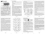
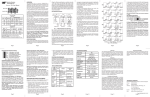
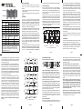
iConverter® 10/100 User Manual
ABOUT THIS MANUAL
or 10/100M module must be installed in the same chassis.
This document supports revision xx/19 or later of the
10/100. This revision incorporates the following
features:
PORT STRUCTURE
1. Product support Flow Control via the on-board DIPswitch selections.
Port 1 (P1)
2. Symmetrical Fault Detection has been added to the
module.
Port 2 (P2)
OVERVIEW
iConverter 10/100 Dual Fiber Modules
Connector Type
Fiber Type
Distance
MM
5 km
SM
30 km
SM
60 km
120 km
-
SM
ST
SC
MT-RJ
LC
8380-0
8382-0
8384-0
8386-0
8381-1
8383-1
8385-1
8387-1
8381-2
8383-2
-
8387-2
8383-3
-
8387-3
iConverter 10/100 Single-Fiber Modules
Fiber /
Connector
Type
Distance
Tx: 1310 nm,
Rx: 1550 nm
Tx: 1550 nm,
Rx: 1310 nm
SM / SC
20 km
8390-1
8391-1
SM / SC
40 km
8390-2
8391-2
SM / SC
60 km
8390-3
8391-3
For wide temperature (-40 to 60º C), add a "W" to the end of
the model number. Consult factory for extended temperature
(-40 to +75º C) models. When using single-fiber (SF) media
converter models, the Tx wavelength on one end has to match
the Rx wavelength on the other.
The iConverter 10/100 converters support the IEEE
802.3 Ethernet standard and convert between Ethernet
10BASE-T or 100BASE-TX unshielded twisted pair (UTP)
and Fast Ethernet fiber 100BASE-FX. Models are
available for multimode (MM) and single-mode (SM)
dual fiber, and single-mode single-fiber.
The 10/100 supports Half-Duplex and Full-Duplex modes
and features a crossover UTP switch for easy
attachment to hubs, switches and workstations.
The 10/100 can be used as a standard two-port UTP to
fiber converter. It can also use its two additional 10/100
backplane ports to connect to adjacent modules and
accommodate flexible network configurations like InBand management and multi-module configurations. The
iConverter 19-Module, 5-Module or 2-Module Chassis
have backplanes that facilitate connectivity between
adjacent modules.
The 10/100 can be used in an unmanaged or managed
fashion. When unmanaged, it can be installed in a chassis
without an iConverter Network Management Module (NMM)
or iConverter 10/100M. To be managed, an NMM module
Page 2
In Link Propagate (LP), a port transmits a Link signal
only when receiving a Link at its other port. For example,
the UTP transmits a Link only when receiving a Link at
the fiber port [Fig. 2(c)].
In Remote Fault Detection + Link Propagate (RFD+LP),
the UTP port transmits a Link signal only when receiving
a Link at the fiber port. The fiber port transmits a Link
signal only when receiving Link signals at both the fiber
port and the UTP port. As a result, fiber faults (no Link
received at the fiber) are propagated forward and looped
back for fault reporting at both the network core and the
customer location [Fig. 2(d)].
In Symmetrical Fault Detection (SFD), the UTP port
transmits a Link signal only when receiving a Link at
the fiber port. The fiber port transmits a Link signal
only when receiving a Link signal at both the fiber port
and the UTP port. As a result, fiber faults (no Link
received at the fiber) are looped back and can be
reported to the network core. In addition, connecting
two back-to-back converters which are both set to
SFD facilitates dual-loop-back, where fiber faults are
reported to both ends of the network. A blinking fiber
link LED on a converter indicates a fault of the transmit
fiber or UTP cables of that converter [Fig. 3(e)].
NOTE: Connecting two converters with both set to
RFD mode is not supported and will cause a lockup.
NOTE: Converters in SFD mode must be deployed
in pairs.
LS
Fiber
LS
Converter A
Converter B
LS
LS
Slot 1
Slot 2
“A” Link
A Port
A Port
Slot 3
“B” Link
NMM
front /
back
select
B Port
A Port
Internal
10/100
switch chip
B Port
Internal
10/100
switch chip
NMM Module
Fiber
100 port
UTP
10/100 port
10/100 Module
4-port 10/100 UTP
Switch
4Tx Module
Fig. 1: 10/100 Application Example
Front Panel DIP-switch Settings
Switch 2
(b)
Converter A
LP
Converter B
LP
Switch 2
Converter A
Converter B
Switch 2
(c)
Switch 1
LP
RFD+LP
Switch 1
Converter A
SFD
Converter B
SFD
Switch 2
(e)
Switch 1
Converter A
Converter B
Switch 2
LED Lit
LED Blinking
LED Off
LED Status depends on connected device
Page 6
When in the Fiber Full/Half-Duplex DIP-switch is in the
Fiber Full-Duplex “FDX” position (factory setting), the
fiber port operates in Full-Duplex mode. When in the
Fiber Half-Duplex “HDX” position, the fiber port operates
in Half-Duplex mode and its distance is limited by the
IEEE 802.3 standard to 412 meters.
UTP Auto/Manual Negotiate “AN / MAN” DIP-switch
(d)
This example shows how the 10/100 can be used either
as a traditional managed or unmanaged media converter
or to create flexible and effective network switch
configurations.
For more information about individual chassis A and B
backplane links, please refer to the specific chassis
user manual.
LINK MODES
In Link Segment (LS), a port transmits a Link signal
independently of any received Link at any other port.
For example, the UTP transmits a Link regardless of
the fiber receiving a Link [Fig. 2(a) & (b)].
Page 4
DIP-switch selects the speed of the UTP port. When in
the “100” position (factory setting), the UTP port operates
at 100 Mbps. When in the “10” position the UTP port
operates at 10 Mbps.
UTP Full/Half-Duplex “FDX / HDX” DIP-switch
Fiber Full/Half-Duplex “FDX/HDX” DIP-switch
Switch 1
In this example, the module on the left is a Network
Management Module (NMM) and it connects via its A
backplane port to the 10/100 facilitating “In-Band”
management (via the fiber uplink). The module on the
right is a 4-port 10/100 switch module (4Tx) and it
connects via its B backplane port to the 10/100 facilitating
a 5-port 10/100 Ethernet switch with a fiber uplink
configuration. This 3-module configuration provides an
effective 5-port 10/100 managed switch with a fiber
uplink configuration.
In order to accommodate different user needs, the 10/100
supports four different linking modes (see Fig. 2).
NMM UTP
10 port
Fig. 3: Front-Panel Dip Switches
Fig. 2: 10/100 Link Modes
Page 5
Chassis
Backplane
DIP-SWITCH SETTINGS
UTP
Fiber
Switch 1
When the 10/100 “A” and “B” ports are enabled (using
the “BPOEN” DIP-Switch), they connect via the chassis’
backplane to the slots on the left and right sides of the
10/100 module. When another switch-based module with
backplane port connections such as a second 10/100 or
an NMM is installed in an adjacent slot, it can be
connected via the backplane to the 10/100 to facilitate
a multi-module configuration.
Page 3
UTP
(a)
Using a 4-port switch design, the 10/100 features a
front-plane 10/100 UTP port, a front-plane 100Mbps
fiber port and two 10/100 Ethernet backplane ports (“A”
and “B”) that can connect to adjacent modules within
the same chassis.
Fig. 1 depicts a chassis with three modules plugged into
three of its adjacent backplane slots. The adjacent slots
are connected via the backplane using the “A” and “B”
10/100 links. In this example, the 10/100 in the center
slot connects to the slot on its left using the “A” link and
to the slot on its right using the “B” link.
When the UTP Auto/Manual Negotiate DIP-switch is in
the UTP Auto-Negotiate “AN” position (factory setting),
the converter auto-negotiates and matches the 10/100
speed and duplex mode of a mating auto-negotiating
device connected to its UTP port.
When the UTP Auto/Manual Negotiate DIP-switch is in
the UTP Manual “Man” position, the converter does not
auto-negotiate and operates in the mode selected by
the Full/Half Duplex “FDX/HDX” and “10/100”
DIP-switches.
When the UTP Auto/Manual Negotiate DIP-switch is in
the UTP Manual “Man” position, the UTP Full/Half-Duplex
“FDX/HDX” DIP-switch selects the duplex mode of the
UTP port. When in the Full-Duplex “FDX” position
(factory setting), the UTP port operates in Full-Duplex
mode. When in the Half-Duplex “HDX” position, the
UTP port operates in Half-Duplex. Set the duplex mode
to match the connecting device and check for link
status.
Note: Attaching an auto-negotiating UTP port to a
non-auto-negotiating (manual / forced / hard-coded)
UTP port may result in an unpredictable port setting
with excessive collisions and poor link
performance. When operating in Manual mode, both
mating ports MUST be set manually to the same
speed and duplex mode.
RJ45 Crossover Push Button Switch (not shown)
When connecting the UTP to a hub or switch, set switch
to “Straight-Through” (factory setting). When connecting
to a workstation, set to “Crossover.”
UTP 10/100 DIP-switch
When the UTP Auto/Manual Negotiate DIP-switch is in
the UTP Manual “Man” position, the UTP “10/100”
Page 7
Page 8
BOARD MOUNTED DIP-SWITCHES
RFD
BPOEN
LP
FLOWEN
4
3
2
1
=
=
=
=
Remote Fault Detect Enable
Backplane Enable
Link Propagate/Link Segment
Flow Control Enable (PAUSE)
Down
Fig. 4 Board Mounted DIP-Switches
LINK MODES (SW4 and SW1)
The module supports multiple link modes for fault
detection and isolation. Link Segment should be used
for the initial installation of the module. Once installed
and operational, the link mode can be modified.
“FLOWEN” Flow Control (PAUSE) DIP-switch
LED INDICATORS:
MOUNTING AND CABLE ATTACHMENT:
When the Flow Control “FLOWEN” DIP-switch is in the
UP position, flow control functionality is enabled. When
the module is configured for FDX, PAUSE functionality
is enabled. When the module is configured for HDX,
jam functionality is enabled. When flow control is
enabled, a port will generate either a pause or jam frame
when internal resources are not available to receive the
next incoming frame.
LED
Power
Fiber FDx:
F/O Link:
COLOR DESCRIPTION
Yellow
On - Power
Green
On - Full-Duplex selected
Green
On - Link
Rapid Blinking - activity
0.5Hz blinking - SFD error detected
iConverter modules are hot-swappable and can be
installed into any chassis in the iConverter family.
UTP Auto:
UTP 100:
UTP 10:
Green
Green
Green
On - Auto-Negotiation enabled
On - 100 Mbps link
On - 10 Mbps link
UTP FDx:
Green
UTP Link:
Green
On - Full-Duplex detected
Blinking - Collision in HDx mode
On - Link
Rapid Blinking - activity
0.5Hz blinking - SFD error detected
When the DIP-switch is in the DOWN position (factory
default), flow control is disabled.
Link modes are controlled by DIP-switch 2 and 4.
SW2
(LP)
SW4
(RDF)
FUNCTION
DOWN
DOWN
Link Segment (LS)
UP
DOWN
Link Propagate (LP)
DOWN
UP
Remote Fault Detect + Link Propagate (RFD+LP)
UP
UP
Symmetrical Fault Detect (SFD)
1. Carefully slide the iConverter module into the
installation slot, aligning the module with the
installation guides.
NOTE: Ensure that the module is firmly seated
against the backplane.
2. Secure the module by securing the panel fastener
screw (attached to module) to the chassis front.
3. Attach the UTP port via a category 5 cable to a
100BASE-TX or 10BASE-T Ethernet device.
4. Attach the fiber port via an appropriate multimode
or single-mode fiber cable to a 100BASE-FX Ethernet
device. The iConverter transmit (Tx) must attach to
the receive side on other device; the receive (Rx)
must attach to the transmit.
5. When using single-fiber (SF) media converter models,
the Tx wavelength on one end has to match the Rx
wavelength on the other. Note that based on this
guideline, the SF media converter models must be used
in pairs, such as the 8390-1 matched with the 8391-1.
“BPOEN” A and B Backplane Enable DIP-Switch
When the A and B Backplane Enable “BPOEN”
DIP-switch is in the UP position, both the A and B
backplane ports are enabled and connect to the
backplane to facilitate In-Band management. When
the “BPOEN” switch is in the DOWN position (factory
setting), both ports are disabled and disconnected from
the backplane.
Page 9
Page 10
SPECIFICATIONS
SPECIFICATIONS
Model Type
Protocols
Frame Size
10/100
100BASE-FX, 10BASE-T,
or 100BASE-TX
up to 1,536 bytes
UTP
Connectors
RJ-45
Fiber
Connectors
SC, ST, LC, MT-RJ,
Single-Fiber SC
Controls
LED Displays
Page 11
UTP X-over,
LS/LP, RFD, SFD,
Auto/Man, 10/100, FDX/HDX,
Flow Control
Power,
F/O FDX/HDX, FO link activity,
Auto, FDX/HDX, 10, 100,
UTP link activity,
Page 13
Dimensions
W:0.850" x D:4.5" x H:2.8"
Weight
Compliance
8 oz.
UL, CE, FCC Class A,
NEBS Level 3
Power
Requirement
0.95A @ 3.3VDC (typical)
Temperature
Standard: 0 to 50º C
Wide: -40 to 60º C
Storage: -40 to 80º C
Humidity
5 to 95% (non-condensing)
Altitude
-100m to 4000m
MTBF (hrs)
1,050,000
Warning
Exclusive Remedies
The operating description in this Instruction Manual is for use by
qualified personnel only. To avoid electrical shock, do not perform any
servicing of this unit other than that contained in the operating
instructions, unless you are qualified and certified to do so by
Omnitron Systems Technology, Inc.
The remedies provided herein are the Buyer’s sole and exclusive
remedies. Omnitron shall not be liable for any direct, indirect, special,
incidental, or consequential damages, whether based on contract, tort,
or any legal theory.
Warranty
This product is warranted to the original purchaser against defects
in material and workmanship for a period of TWO YEARS from the
date of shipment. A LIFETIME warranty may be obtained by the
original purchaser by REGISTERING this product with Omnitron
within 90 days from the date of shipment. TO REGISTER,
COMPLETE AND MAIL OR FAX THE ENCLOSED
REGISTRATION FORM. Or you may register your product on the
Internet at www.omnitron-systems.com. During the warranty period,
Omnitron will, at its option, repair or replace a product which is
proven to be defective.
For warranty service, the product must be sent to an Omnitron designated
facility, at Buyer’s expense. Omnitron will pay the shipping charge to
return the product to Buyer’s designated US address using Omnitron’s
standard shipping method.
Limitation of Warranty
The foregoing warranty shall not apply to defects resulting from improper
or inadequate use and/or maintenance of the equipment by Buyer, Buyersupplied equipment, Buyer-supplied interfacing, unauthorized
modifications or tampering with equipment (including removal of
equipment cover by personnel not specifically authorized and certified
by Omnitron), or misuse, or operating outside the environmental
specification of the product (including but not limited to voltage, ambient
temperature, radiation, unusual dust, etc.), or improper site preparation
or maintenance.
No other warranty is expressed or implied. Omnitron specifically
disclaims the implied warranties of merchantability and fitness for any
particular purpose.
Page 14
Page 12
Page 15
TECHNICAL SUPPORT:
For help with this product, contact our Technical Support:
Phone:
(949) 250-6510
Fax:
(949) 250-6514
Address: Omnitron Systems Technology, Inc.
140 Technology Dr., #500
Irvine, CA 92618 USA
E-mail:
[email protected]
URL:
www.omnitron-systems.com
Form: 040-08380-001M 6/11
Page 16