Transcript
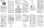
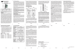
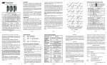
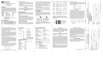
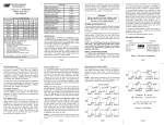
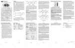
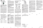
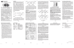
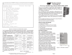
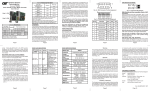
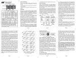
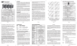
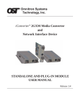
OVERVIEW: iConverter® RS422/485 Serial RS-422 and RS-485 to Fiber Media Converter User Manual The RS422/485 is available with a single-mode, multimode or single-fiber transceiver. The serial port interface is available with a DB-9 female connector or terminal block connector for field wiring. Port 1 (P1) iConverter RS422/485 DB-9 Models Fiber Type / Dual Fiber [DF] or Single-Fiber [SF] / Wavelength Distance ST SC LC MM/DF/1310nm 5km 8780-0 8782-0 8786-0 SM/DF/1310nm 30km 8781-1 8783-1 8787-1 SM/DF/1310nm 60km 8781-2 8783-2 8787-2 SM/DF/1550nm 120km - 8783-3 8787-3 Fiber Connector Types iConverter RS422/485 Single-Fiber Models 20km - 8790-1 - 20km - 8791-1 - 40km - 8790-2 - 40km - 8791-2 - For wide temperature (-40 to 60 o C), add a "W" to the end of the model number. Consult factory for extended temperature (-40 to 75 o C) models. When using single-fiber (SF) media converter models, the Tx wavelength on one end has to match the Rx wavelength on the other. When ordering module with terminal block serial port, append 'T' before the dash '-' in the model number. Examples: 8780T-0, 8783T-3 The RS422/485 is designed to work in any iConverter chassis. When installed in a multi-module chassis with an iConverter Management Module, the RS422/485 can be remotely monitored and managed by software control. Management is supported on the iConverter 19-Module, 5-Module and 2-Module chassis. The 1-Module chassis supports RS422/485 as a standalone serial to fiber converter. Note that software control for remote configuration of the RS422/485 requires a multi-module chassis with an iConverter Management Module, such as the Network Management Module (NMM). Page 2 “NORM” position (factory default), the RS422/485 operates in a point-to-point Full-Duplex mode, commonly used by the RS-422 protocol. Baud rate selection is automatic in this mode. providing parallel terminations. When these DIP-Switches are in the “MID” position (factory default), no termination is provided. Setting these DIP-Switches to the “H-T” position provides parallel termination. See the Termination Table and Fig. 6 for details. Board-Mounted Bank 2 DIP-Switches: Note that Bank 2 DIP-Switches are not accessible via software control, and must be configured physically. Front-Panel Ports: The front-panel of the iConverter RS422/485 features one fiber port (P1) and one RS-422/485 capable serial port (P2). Depending on the model, the serial port is available either as a DB-9 female connector or as a terminal block for field wiring. Please refer to Fig. 1a, Fig. 1b and the Pin-Out Signal Assignment Table for connector pin-out assignment. Fig. 1a DB-9 Connector Pin-Out Assignment A built-in remote Fiber Loop-Back DIP-Switch provides easy validation of the fiber segment. The Loop-Back does not interrupt signal transmission over the fiber. Built-in configurable terminators support Full-Duplex and Half-Duplex operations, allowing the unit to be deployed and terminated at any node in the serial line. Termination Table Full-Duplex Mode Switch No. Head Tail Mid 1 OFF OFF OFF 2 OFF OFF OFF 3 ON ON OFF 4 ON ON OFF 5 ON ON OFF 6 ON ON OFF RS-485 Half-Duplex Mode Head Tail Mid ON ON ON ON ON ON OFF OFF OFF OFF OFF OFF RS-485 Fiber TM T M iC o n v e r et r iC o n v re te r iC o n v e tr re OFF OFF ON ON ON ON b y Om n tro i n S y s te m s T e c n o o l g y,In c . Fig. 1b Terminal Block Pin-Out Assignment Pin-Out Signal Assignment Table Full-Duplex Full-Duplex Half-Duplex PIN Normal (Point-to-Point) Multi-Point Multi-Point No. Signal DTE DCE 1 Ground - - Reserved 2 RTS+ OUT IN Reserved Reserved 3 RTS- OUT IN Reserved Reserved 4 TXD+ OUT IN TXD+ (IN) DATA+ 5 TXD- OUT IN TXD- (IN) DATA 6 CTS+ IN OUT Reserved Reserved 7 CTS- IN OUT Reserved Reserved 8 RXD+ IN OUT RXD+ (OUT) Reserved 9 RXD- IN OUT RXD- (OUT) Reserved Master “HEAD” RS422/485 “TAIL” iC o n v e r et r iConverter modules are hot-swappable and can be installed into any chassis in the iConverter family. 1. After configuring the DIP-Switches, carefully slide the iConverter module into the installation slot, aligning the module with the installation guides. Ensure that the module is firmly seated against the Backplane. 2. Secure the module by fastening the panel thumb screw (attached to the module) to the chassis front. 3. Attach the serial ports via a DB-9 serial cable (or an openend serial cable) to a serial RS-422 or RS-485 device. 4. Attach the fiber port via an appropriate multimode or single-mode fiber cable to a 100BASE-FX Fast Ethernet device. The iConverter transmit (Tx) must attach to the receive side on the other device; the receive (Rx) must attach to the transmit side. 5. When using single-fiber (SF) media converter models, the Tx wavelength on one end has to match the Rx wavelength on the other. Note that based on this guideline, the SF media converter models must be used in pairs, such as the 8790-1 matched with the 8791-1. RS422/485 “HEAD” Master “HEAD” SW2 SW3 SW4 L L L L 300 R L L L 1200 L R R R L L L L 2400 4800 9600 19.2K Note that the Fiber Loop-back test does not interfere with serial conversion and signal transmission. Note that if both RS422/485 on the ends of a fiber segment are set to the “FLB” position during the Loop-back test, then both RS422/485 would still display valid master mode results. SW2: Serial “DCE - DTE” DIP-Switch: When the “DCE - DTE” DIP-Switch is in the “DCE” position (factory default), the RS422/485 is configured to connect to Data Communications Equipment such as a modem or printer. Setting this DIP-Switch to the “DTE” position configures the RS422/485 to connect to Data Terminal Equipment such as a computer or controller. Please refer to the PORT STRUCTURE section of this manual for more details. 38.4K 57.6K Fig. 3 Board-Mounted DIP-Switches OFF ON BAUD 0 BAUD 1 BAUD 2 BAUD 3 FDX / HDX RSV RSV NORM/MP Baud Rate Selection = (See Table on Page 6) = Full or Half-Duplex = Reserved = Point-to-Point or Multi-Point Full-Duplex Fig. 4 Bank 1 DIP-Switch Description Bank1 SW1 through SW4: Baud Rate Selection for RS-485 “BAUD” DIP-Switches: Bank 1 “BAUD” DIP-Switches 1 through 4 configure the baud rate when the RS422/485 is operating in Half-Duplex mode or in Multi-point Full-Duplex mode. These DIP-Switches are deactivated when the RS422/485 is operating in point-to-point Full-Duplex RS-422 Mode. Please see the Baud Rate Configuration Table for details. LED Function Color "Legend" Power "Pwr" Off State Page 5 Amber No Power Fiber LoopNormal Green back Test "Tst" Mode Fiber Link and No Fiber Green Activities "Act" Link Module has power Solid: Master mode Tx pattern sent, but no Rx received 10 Hz (Blinking 10x per second): Master mode, Tx pattern sent, and Rx pattern received 1 Hz (Blinking once per second): Slave mode, Rx pattern received Solid: Fiber Link Active Blinking: Fiber Data Transmission "DTE" Mode DTE mode Green DTE mode selected not selected "DCE" Mode Green DCE mode DCE mode selected not selected Serial data received Model Type Protocols L R R R L L L L R L L L L R R L R L R R L L L R R R R 921K 921K R L R R 921K L R R R 921K R R R R L designates the LEFT (OFF) position of the DIP-switch R designates the RIGHT (ON) position of the DIP-switch Bank1 SW5: Full/Half-Duplex “FDX/HDX” DIP-Switch: When the Full/Half-Duplex selection DIP-Switch is in the LEFT “FDX” position (factory default), the RS422/485 operates in serial Full-Duplex mode. Configuring the DIP-Switch to the RIGHT “HDX” position enables serial Half-Duplex mode, often used by the RS-485 protocol. When the RS422/485 is in Half-Duplex mode, the pointto-point/Multi-point DIP-Switch has no effect. Configure the Half-Duplex Baud rate with Bank 1 DIP-Switches 1 through 4. Warranty RS422/485 Asynchronous Serial RS-422, Serial RS-485 Copper Connectors DB-9 Female or Terminal Block Fiber Connectors ST, SC, LC Controls LED Displays Dimensions DTE/DCE, Fiber Loop-Back, Baud Rate, Termination Power, Test, Fiber Lnk/Act, DTE, DCE, Serial Act W:0.85" x D:4.5" x H:2.8" This product is warranted to the original purchaser against defects in material and workmanship for a period of TWO YEARS from the date of shipment. A LIFETIME warranty may be obtained by the original purchaser by REGISTERING this product with Omnitron within 90 days from the date of shipment. TO REGISTER, COMPLETE AND MAIL OR FAX THE ENCLOSED REGISTRATION FORM TO THE INDICATED ADDRESS. Or you may register your product on the Internet at www.omnitronsystems.com. During the warranty period, Omnitron will, at its option, repair or replace a product which is proven to be defective. For warranty service, the product must be sent to an Omnitron designated facility, at Buyer ’s expense. Omnitron will pay the shipping charge to return the product to Buyer’s designated US address using Omnitron’s standard shipping method. Limitation of Warranty Weight 8 oz. Compliance UL, CE, FCC Class A Power Requirement 0.5A @ 3.3VDC (typical) Temperature Standard: Wide: Storage: 0 to 50º C -40 to 60º C -40 to 80º C Humidity 5 to 95% (non-condensing) TECHNICAL SUPPORT: Altitude -100m to 4000m For help with this product, contact our Technical Support: Phone: (949) 250-6510 Fax: (949) 250-6514 Address: Omnitron Systems Technology, Inc. 140 Technology Dr. Irvine, CA 92618 USA E-mail: [email protected] URL: www.omnitron-systems.com MTBF (hrs) ` R L R R Page 6 RS422/485 SPECIFICATIONS: On States L Bank1 SW8: Full-Duplex Normal/Multi-Point “NORM/MP” DIP-Switches: This DIP-Switch has no affect if the RS422/485 is in Half-Duplex mode. When this DIP-Switch is in the LEFT Page 4 RS422/485 LED INDICATORS: 115K 230K 460K L R L R Bank1 SW6 and SW7: “RSV” DIP-Switches: DIP-Switches 6 and 7 in Bank 1 are reserved for factory use and must be kept in the LEFT position. Note that the “DCE - DTE” DIP-Switch is disabled if the RS422/485 is in Half-Duplex mode or in Multipoint mode. Slave “TAIL” RS-485 SW1 110 Fig. 2 Front-Panel DIP-Switches Serial No serial Green Activities "Act" data Slave “TAIL” Baud Rate SW1: Normal and Fiber Loop-Back “Norm - FLB” DIP-Switch: When the Normal and Fiber Loop-Back “Norm - FLB” DIP-Switch is in the normal mode “Norm” position (factory default), the Fiber Loop-Back is disabled. Setting this DIP-Switch to the “FLB” position on the RS422/485 at either end of the fiber segment will enable the Fiber LoopBack test. When Fiber Loop-Back is enabled, the local RS422/485 with the DIP-Switch in “FLB” position is the master, and the remote RS422/485 with the DIP-Switch in “Norm” position is the slave. The “Tst” LED on the master will blink rapidly (10 times per second) and the “Tst” LED on the slave will blink slowly (once per second) if the fiber segment passes the Loop-Back test. If the fiber segment fails the Loop-Back test, the “Tst” LED will remain solid on the master unit. Fig. 6a Head and Tail Termination Application The foregoing warranty shall not apply to defects resulting from improper or inadequate use and/or maintenance of the equipment by Buyer, Buyer-supplied equipment, Buyer-supplied interfacing, unauthorized modifications or tampering with equipment (including removal of equipment cover by personnel not specifically authorized and certified by Omnitron), or misuse, or operating outside the environmental specification of the product (including but not limited to voltage, ambient temperature, radiation, unusual dust, etc.), or improper site preparation or maintenance. TM iC o nv e tr re Fig. 5 Bank 2 DIP-Switch Description Bank2 SW1 and SW2: Head Termination “HEAD” DIP-Switches: Bank 2 Head Termination “HEAD” DIP-Switches 1 and 2 configure the RS422/485’s termination setting by providing termination on the data line. When these DIP-Switches are in the LEFT “-” position (factory default), no termination is provided. Setting these DIP-Switches to the RIGHT “HEAD” position provides pull-up and pulldown on the data lines. See the Termination Table on page 8 and Fig. 6 for details. Ground MOUNTING AND CABLE ATTACHMENT: b y O mn tro i n Sy s e t ms T e c n o o l g y,In c . ` Baud Rate DIP-Switch Configuration Table Front-Panel DIP-Switches Page 3 Note that all of the Mid Termination “MID/H-T” DIP-Switches on a RS422/485 need to be set to the same position, failure to do so will result in unpredictable behavior. Board-Mounted DIP-Switches: DIP-SWITCH SETTINGS: PORT STRUCTURE: Half-Duplex RS-485 and Full-Duplex RS-485 (sometimes referred as Multi-point RS-422) operation is supported via a configurable baud rate DIP-Switch to match the master/ slave communication timing. Page 1 When this DIP-Switch is in the RIGHT “MP” position, the RS422/485 operates in a Multi-point Full-Duplex mode, often referred as Full-Duplex RS-485 or Multi-point RS-422. In this mode, Baud rate must be manually configured via Bank 1 “BAUD” DIP-Switches 1 through 4. Please see the Baud Rate Configuration Table for details. For more information on using and configuring the RS422/485 via software control, please refer to the NetOutlook™ Management Software user manual. 1 2 3 4 5 6 7 8 The RS422/485 automatically detects the signal baud rate of the connected point-to-point Full-Duplex RS-422 serial devices, ranging from 110 to 921,600 baud. The RS422/485 also automatically adjusts to changes in the point-to-point Full-Duplex RS-422 baud rate during operation, without interrupting the data service. Connection to DTE or DCE Full-Duplex point-to-point RS-422 devices is configured by an easily accessible DIP-Switch on the front-panel. Port 2 (P2) SM/SF/ Tx 1310/Rx 1550 SM/SF Tx 1550/Rx 1310 SM/SF/ Tx 1310/Rx 1550 SM/SF Tx 1550/Rx 1310 The Omnitron iConverter RS422/485 is a manageable serial RS-422 or RS-485 to fiber converter that transmits serial protocol over fiber media. Fiber transmission extends serial signals up to 120km and protects against electrical and magnetic interference. iC o n v e r et r b y Om n tro i n S ys e t ms T e c n o o l g , yn I c . RS422/485 “MID” Fiber Note that both of the Head Termination “HEAD” DIP-Switches on a RS422/485 need to be set to the same position, failure to do so will result in unpredictable behavior. iC o nv e tr re TM iC o n v e r et r b y Om n tro i n S ys e t ms T e c n o o l g , yn I c . RS422/485 “HEAD” RS-485 Slave “TAIL” Bank2 SW3 through SW6: Mid Termination “MID/H-T” DIP-Switches: Bank 2 Mid Termination “MID/H-T” DIP-Switches 3 through 6 configure the RS422/485’s termination setting by Fig. 6b Mid and Head Termination Application Page 7 Page 8 Page 9 Page 10 850,000 No other warranty is expressed or implied. Omnitron specifically disclaims the implied warranties of merchantability and fitness for any particular purpose. Exclusive Remedies Warning The operating description in this Instruction Manual is for use by qualified personnel only. To avoid electrical shock, do not perform any servicing of this unit other than that contained in the operating instructions, unless you are qualified and certified to do so by Omnitron Systems Technology, Inc. Page 11 The remedies provided herein are the Buyer’s sole and exclusive remedies. Omnitron shall not be liable for any direct, indirect, special, incidental, or consequential damages, whether based on contract, tort, or any legal theory. Form: 040-08780-001G 12/12 Page 12