1
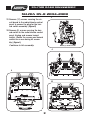
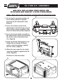
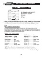
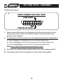
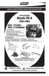
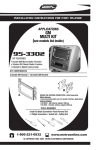
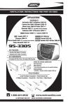
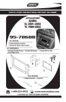
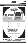
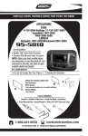
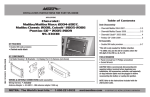
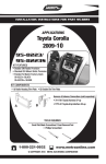
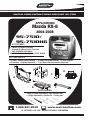
INSTALLATION INSTRUCTIONS FOR PART 95-7510
APPLICATIONS
Mazda RX-8
2004-2008
95-7510/
95-7510HG
KIT FEATURES
• Double DIN Radio Provision
• Stacked ISO Mount Units Provision
• TWO FINISHES AVAILABLE:
99-7510=BLACK, 99-7510HG=GLOSS BLACK
KIT COMPONENTS
• A) Radio / Climate Control Housing • B) Double DIN Radio Brackets • C) Rear Support
• D) Interface • E) Wiring Harnesses • F) (2) Climate Control Extension Harnesses
D
B
A
C
F
E
TOOLS REQUIRED:
Small Flat Blade Screwdriver/ Panel Removal Tool
• Phillips Screwdriver • Socket Set • Cutting Tool
1-800-221-0932
www.metraonline.com
© COPYRIGHT 2004-2008 METRA ELECTRONICS CORPORATION
95-7510
TABLE OF CONTENTS
Dash Disassembly
- Mazda RX-8 2004-2008 . . . . . . . . . . . . . . . . . . . . . . . . . . . .1,2,3
Kit Assembly
- Double DIN Radio Provision / Stacked ISO Mount Units Provision . . . . 4
Final Assembly . . . . . . . . . . . . . . . . . . . . . . . . . . . . . . . . . . . . . . . . .5,6
Display Customization . . . . . . . . . . . . . . . . . . . . . . . . . . . . . . . . . . . . . .7
*Note:
Refer also to the instructions included with the aftermarket radio.
KNOWLEDGE IS POWER
Enhance your installation and fabrication skills by
enrolling in the most recognized and respected
mobile electronics school in our industry.
Log onto www.installerinstitute.com or call
800-354-6782 for more information and take steps
toward a better tomorrow.
AC
FM1 877
95-7510 DASH DISASSEMBL
Y
MAZDA RX-8 2004-2008
A
1 Disconnect the negative battery terminal to prevent an accidental short
circuit.
2 Unscrew the shift knob counter clockwise to remove. (Figure A)
3 Unclip and remove the shifter trim
panel. (Figure B)
4 Remove (2) Phillips screws from the
bottom of the ashtray assembly then
unclip and remove the assembly.
(Figure C)
B
FM1
877
AC
5 Unclip and remove the knee panel on
the driver’s side under the steering
column (Figure D) then remove (1) 10
MM bolt from the side of the radio
bracket. (Figure E)
Continued on page 2.
C
D
FM1
1
877
AC
95-7510 DASH DISASSEMBLY
MAZDA RX-8 2004-2008
E
6 Remove (2) Phillips screws from the
bottom of the radio/climate control
panel. (Figure F)
FM1
877
7 Unsnap radio/climate control panel
including radio chassis. Unplug and
remove panel and chassis. (Figure G)
8 Remove (3) Phillips screws securing
the factory display harness to the
radio chassis. Unplug and remove
display harness. (Retain display harness for re-use during kit assembly.)
(Figure H)
FM1
877
F
9 Remove (4) screws securing the radio
chassis to the radio/climate control
panel. (Figure I)
10 Remove (6) screws securing the climate controls from the radio/climate
control panel. Unplug and remove the
climate controls. (Retain the screws
and climate controls for re-use during
kit assembly.) (Figure J)
Continued on page 3.
G
H
FM1
2
877
AC
AC
AC
95-7510 DASH DISASSEMBLY
MAZDA RX-8 2004-2008
I
11 Remove (17) screws securing the circuit board to the radio/climate control
panel to access the plug for the hazard switch assembly. (Figure K)
12 Remove (2) screws securing the hazard switch to the radio/climate control
panel. Unplug and remove hazard
switch. (Retain the screws and hazard
switch for re-use during kit assembly.) (Figure L)
Continue to kit assembly.
REMOVE (2) SCREWS PER SIDE
J
L
K
3
95-7510 KIT ASSEMBLY
DOUBLE DIN RADIO PROVISION OR
STACKED ISO MOUNT UNITS PROVISION
*Note: Refer also to the instructions included with the aftermarket radio.
A
1 Cut the top (2) mounting locations off
of the climate controls to provide
clearance for the aftermarket radio.
(Figure A)
2 Secure the climate control to the
radio/climate control housing using (4)
of the factory screws removed in step
(10) of the dash disassembly. (Figure B)
3 Secure the hazard switch assembly to
the radio/climate control housing using
the factory screws removed in step
(12). (Figure B)
B
4 Attach the Double DIN brackets to the
Double DIN or stacked ISO Mount
unit(s) using the hardware supplied
with the unit(s). (Figure C)
0 1
5 Attach the rear support to the unit(s)
using the hardware supplied with the
unit(s). (Figure D)
2
3
4
Continue to final assembly.
C
D
4
A/
C
95-7510 FINAL ASSEMBLY
FINAL ASSEMBLY
A
B
(A) Strip wire ends back 1/2"
B) Twist ends together
C) Solder
C
D) Tape
D
1
Locate the factory wiring harness in the dash. Use the supplied wire harnesses and
make the connections as shown. (Isolate and individually tape off the ends of any
unused wires to prevent electrical short circuit). Refer to Metra/EIA Wiring Code
below.
FINAL WIRING CONNECTIONS
Make wiring connections using the EIA color code chart shown below and the
instructions included with the head unit. Metra recommends making connections as
shown below; Strip, Splice, Solder, Tape. Isolate and individually tape off ends of any
unused wires to prevent electrical short circuit.
METRA / EIA WIRING CODE
12V Ignition / Acc. . . . . . Red
Right Front (+) . . . . . . . . Gray
12V Batt / Memory . . . . . Yellow
Right Front (-). . . . . . . . . Gray/ Black
Ground . . . . . . . . . . . . . . Black*
Left Front (+) . . . . . . . . . White
Power Antenna . . . . . . . . Blue
Left Front (-) . . . . . . . . . . White / Black
Amp Turn-On . . . . . . . . . Blue / White
Right Rear (+). . . . . . . . . Violet
Amp Ground . . . . . . . . . . Black / White
Right Rear (-) . . . . . . . . . Violet / Black
Illumination . . . . . . . . . . Orange
Left Rear (+) . . . . . . . . . . Green
Dimmer . . . . . . . . . . . . . . Orange / White
Left Rear (-) . . . . . . . . . . Green / Black
*NOTE: When a Black wire is not present, ground radio to vehicle chassis.
All colors may not be present on all leads due to manufacturer’s specifications.
Continued on Page 6
5
95-7510 FINAL ASSEMBLY
Continued from Page 5
WARNING!
FAILURE TO INSERT THE HVAC CABLES INTO THE CORRECT
LOCATION WILL CAUSE DAMAGE TO THE INTERFACE AND MAKE
THE DISPLAY AND HVAC CONTROLS NOT FUNCTION PROPERLY
2 Attach the (2) climate control extension harnesses to the temperature control
cable and the fan control cable on the factory climate control.
3 Plug the Temperature Control cable from the factory climate control into the port
on the interface that reads “TEMP”.
4 Plug the Fan Control cable from the factory climate control into the port on the
interface that reads “FAN”.
5
Plug the Display cable removed in step 8 of the dash disassembly into the port
on the interface that reads “DISP”.
6
Plug the Hazard Switch extension cable into the end of the hazard switch and
the other end of the extension cable into the port next to the “DISP” port.
Continued on Page 7
6
95-7510 FINAL ASSEMBLY
Continued from Page 6
A
OBDII CONNECTOR FACE VIEW
PINK WIRE
1 2 3 4 5 6 7 8
9 10 11 12 13 14 15 16
PINK/BLUE WIRE
7
When using the Nav features of the interface you will need to connect the 2 pin
harness and run the 2 wires to the OBDII connector and connect them in the
position shown. (Figure A)
8
The following wires on the 10 pin harness are for the aftermarket radios that have navigation built in:
A. Connect the green wire to the parking brake wire of the aftermarket navigation radio.
B. Connect the pink /blue wire to the VSS or speed sense wire of the aftermarket navigation radio.
C. Connect the green/purple wire to the reverse wire of the aftermarket navigation radio.
NOTE: Reverse output is NOT present on manual transmission vehicles.
9
Re-connect the negative battery terminal and test the unit for proper operation.
10 Reassemble radio and dash assemblies in reverse order of disassembly.
7
OPEN
TILT
FM1
877
AC
95-7510 KIT ASSEMBLY
DISPLAY CUSTOMIZATION
*Note: Refer also to the instructions included with the aftermarket radio.
1
2
0
3
A/C
4
OPEN
TILT
FM1
MODE
877
AC
1 Press and hold the A/C Mode button to scroll through the various kit options (AMB
TEMP ON or OFF, AMB TEMP C or F, SET TIME 12/24H, and SET TEXT).
2 When you see the option you want just let the button go and the action on the
screen will be performed. (ie: To turn the ambient temperature on you would scroll
through until the display says “AMB TEMP ON” and let the button go.)
1
2
0
3
A/C
4
MODE
3 To set the time hold down the A/C Mode button until the display says “SET TIME
12/24H” then let the button go.
4 To switch between 12H and 24H press the front defrost button to the left of the
A/C Mode button.
5 To change the Hour press the rear defrost button to the right of the A/C Mode
button.
6 To change the minute press the A/C button at the top of the A/C Mode button.
7 At any time if you do not press any buttons for 5 seconds the display will save and
return to the default screen and the climate control buttons will return to their
normal configuration.
8 If you hold the A/C Mode button down long enough the display will say “SET
TEXT”. This will allow you customize the default text on the display.
9 Once the display says “SET TEXT” let go and the first letter of the display will begin
blinking.
10 Press the front defrost button to move the cursor left and the rear defrost button
to move the cursor to the right.
11 You can scroll up with the A/C button and down with the Recirc/Fresh button
through the various alpha, numeric, and symbol characters.
12 When you are finished entering your text if you do not press any buttons for 5 seconds the display will save and return to the default screen and the climate control
buttons will return to their normal configuration.
8
95-7510
NOTES
9
95-7510 INSTRUCTIONS
1-800-221-0932
www.metraonline.com
REV. 10/30/08 © COPYRIGHT 2004-2008 METRA ELECTRONICS CORPORATION INST95-7510