1
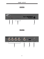
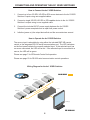
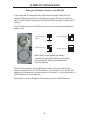
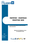
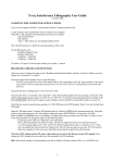
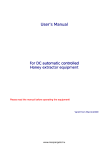
®
4x1 3GSDI
Switcher
EXT-3GSDI-441
User Manual
www.gefen.com
ASKING FOR ASSISTANCE
Technical Support:
Telephone
Fax
(818) 772-9100
(800) 545-6900
(818) 772-9120
Technical Support Hours:
8:00 AM to 5:00 PM Monday thru Friday.
Write To:
Gefen Inc.
c/o Customer Service
20600 Nordhoff St
Chatsworth, CA 91311
www.gefen.com
[email protected]
Notice
Gefen LLC reserves the right to make changes in the hardware, packaging, and
any accompanying documentation without prior written notice.
4x1 3GSDI Switcher is a trademark of Gefen, LLC
© 2011 Gefen, LLC. All rights reserved.
All trademarks are the property of their respective companies.
Rev A6
CONTENTS
1
Introduction
2
Operation Notes
3
Features
4
Panel Layout
5
Panel Descriptions
6
Connecting And Operating The 4X1 3GSDI Switcher
6
Wiring Diagram
7
IR Remote Description
8
IR Remote Configuration
9
DIP Switches
10 RS-232 Serial Control Interface
11 Specifications
12 Warranty
INTRODUCTION
Congratulations on your purchase of the 4x1 3GSDI Switcher. Your complete
satisfaction is very important to us.
Gefen
Gefen delivers innovative, progressive computer and electronics add-on solutions
that harness integration, extension, distribution and conversion technologies.
Gefen’s reliable, plug-and-play products supplement cross-platform computer
systems, professional audio/video environments and HDTV systems of all sizes
with hard-working solutions that are easy to implement and simple to operate.
The Gefen 4x1 3GSDI Switcher
The Gefen 4x1 3GSDI Switcher allows any one of four high-bandwidth 3G-SDI,
HD-SDI or SDI sources to be switched to a single output without a switching
delay or loss of signal quality. Ideal for cutting equipment costs in the studio by
enabling shared signal routing, this product supports source resolutions up to
1080p and has convenient switching methods.
How It Works
Up to four 3G-SDI sources connect to BNC input jacks on one side of the Gefen
4x1 3GSDI Switcher. A single 3G-SDI output connects on the output side. Power
is applied to the 4x1 3GSDI Switcher and a vibrant video picture is transmitted
to the output device. Any 3G-SDI input source is selectable via the included
IR remote control or a selector button on the front panel of the 4x1 3GSDI
Switcher. Selection of sources may also be performed by using the RS-232
communications port.
1
OPERATION NOTES
READ THESE NOTES BEFORE INSTALLING OR
OPERATING THE 4X1 3GSDI SWITCHER
The 4x1 3GSDI Switcher will accept the following formats:
•
SDI - SMPTE 259M-C (270Mbps)
•
HD-SDI -SMPTE 292M (1.485, 1.485/1.001 Gbps)
•
3G-SDI-SMPTE 424M/425M (2.97/3.0 Gbps)
2
FEATURES
Features
•
Switches four 3G-SDI sources instantly without signal degradation
•
Streamlines equipment by eliminating unnecessary hardware
•
Switching is accomplished 3 ways -- by using the optional IR remote, the
front panel selector button, or the RS-232 interface.
•
Video resolutions up to 1080p are supported
•
Backwards compatible with SDI and HD-SDI audio/video formats
•
Plug-and-play installation
•
Distributes video without latency
Package Includes
(1) 4x1 3GSDI Switcher
(1) IR Remote Control Unit
(1) 5V DC Locking Power Supply
(1) 6ft DB9 Cable ( M-F)
(1) User Manual
3
PANEL LAYOUT
Front Panel
1
2
3
4
Back Panel
5
6
4
7
8
PANEL DESCRIPTIONS
1
IR (Infrared) Receiver
This receiver will accept command for switching between input devices using
the included RMT-4IR remote control. Line of sight must be preserved between
the remote and unit for proper operation.
2
Power LED Indicator
This LED will become active once the included 5V DC power supply is properly
connected between the unit and an open wall power socket.
3
Selected Input LED Indicator
There is a 4 LED array to indicate which source is currently selected on the 4x1
3GSDI Switcher. The currently selected input will be indicated by an active LED.
4
3G-SDI Input Source Selector Button
Pressing this button will manually switch between as many as four SDI sources
connected on the rear of the Switcher. The inputs ports (item 5 below) can
accept (up to four) 3G-SDI, HD-SDI or SDI capable devices. The selected
input source is sent to the single output. Selection of input sources may also
be accomplished using the included RMT-4IR remote control or via the RS-232
serial communication port.
5
3G-SDI Inputs 1-4
These inputs ports can accept BNC connections from (up to four) 3G-SDI, HDSDI or SDI capable devices.
6
3G-SDI Output
This output will accept a single 3G-SDI, HD-SDI or SDI output device with a
standard BNC connector.
7
RS-232 Serial Communications Port
This port is used to control input source swithcing on the 4x1 3GSDI Switcher.
Please see page 10 for complete details on the serial communication features
that are used on this product.
8
5V DC Power Receptacle
This receptacle will require power from the included 5V DC power supply for
proper operation. Connect the included power supply between this port and an
open wall power socket.
5
CONNECTING AND OPERATING THE 4X1 3GSDI SWITCHER
How to Connect the 4x1 3GSDI Switcher
1.
Connect up to four 3G-SDI, HD-SDI or SDI source devices to the 4x1 3GSDI
Switcher’s inputs using user supplied cables.
2.
Connect a single 3G-SDI, HD-SDI or SDI capable device to the 4x1 3GSDI
Switcher’s outputs using a user supplied cable.
3.
Connect the included 5V DC power supply between the 4x1 3GSDI
Switcher’s power receptacle and an open wall power socket.
4.
Initialize (power on) the output device first and the source devices second.
How to Operate the 4x1 3GSDI Switcher
The source input is selectable by using either the included RMT-4IR remote
control or the integrated RS-232 serial communication port. The LED indicators
on the front panel indicate the currently selected input. If the selected input has
no source connected, the LED will be red. If the selected input is connected to a
source, the LED will be green.
Please see page 7 for IR Remote Control Unit operation.
Please see page 10 for RS-232 serial communication control operations.
Wiring Diagram for the 4x1 3GSDI Switcher
3G-SDI Source
3G-SDI CABLE
3G-SDI Source
3G-SDI Source
Switcher
3G-SDI Source
3G-SDI Display
EXT-3GSDI-441
6
IR REMOTE DESCRIPTION
The included RMT-4IR remote control is used to switch between inputs on the 4x1
3GSDI Switcher. Only one input can be selected at a time and this input is then
output to the connected SDI output device.
Example: Switch to the 3G-SDI source connected to In 3.
Point the Remote at the 4x1 3GSDI Switcher and press button 3 on the IR
Remote Control Unit.
Table of IR Remote Commands
for the Optional RMT-4IR Remote Unit
RMT-4IR Button
Source
1
1
2
2
3
3
4
4
7
IR REMOTE CONFIGURATION
Setting the IR Remote Channel on the RMT-4IR
In the event that IR commands from other remote controls conflict with the
supplied IR Remote Control Unit, changing the remote IR channel will fix this
issue. The IR Remote Control Unit has a bank of DIP switches for setting the IR
channel.
The DIP Switch bank on the IR Remote Control Unit is located underneath the
battery cover.
Remote Channel 1:
Default
Remote Channel 2:
1
2
Remote Channel 3:
1
2
1
2
Remote Channel 4:
1
2
Left: Picture of the opened rear battery
compartment of the RMT-4IR remote showing
the exposed DIP Switch bank between the
battery chambers.
The IR channel selected on the IR Remote Control Unit must match the IR
channel assigned to the 4x1 3GSDI Switcher. For example, if you set both DIP
switches on the remote to the down position (IR channel 1), you must set the 4x1
3GSDI Switcher to use IR channel 1.
See page 9 on how to change the IR channel on the 4x1 3GSDI Switcher.
8
DIP SWITCHES
4x1 3GSDI Switcher Configuration
On the bottom of the unit, there is a bank of four (4) DIP switches. Each DIP
switch performs a different function.
1 2 3 4
DIP 1 - Termination Mode
ON - 100Ω Termination
•
Adds a 100Ω termination on the RS-485 line. This DIP switch should only be
used when RS-485 is enabled and if the line is to be terminated, usually on
the last device in the chain.
OFF (default) - No Termination
•
For normal use and when using the RS-232 protocol.
DIP 2 - RS-232 / RS-485 Protocol
ON - RS-485
•
Sets the product to use the RS-485 serial protocol. DIP switch 1 should be
set to the ON position. Refer to DIP switch 1 information, above.
OFF - RS-232
•
Sets the product to use the RS-232 serial protocol.
DIP 3 / DIP 4 - IR Channel
•
The IR channel assigned to the IR Remote Control must match the IR
channel assigned to the 4x1 3GSDI Switcher. The factory setting (default)
for DIP 3 and DIP 4 are in the OFF position. See page 8 for setting the IR
channel on the IR Remote Control Unit.
DIP 3
DIP 4
IR Channel
OFF
OFF
1
ON
OFF
2
OFF
ON
3
ON
ON
4
9
RS-232 SERIAL CONTROL INTERFACE
54321
12345
9876
6789
Only Pins 2 (RX), 3 (TX), and 5 (Ground) are used on the RS-232 serial interface
What are the communication port settings?
Bits per second ............................................................................................ 19200
Data bits ............................................................................................................... 8
Parity ............................................................................................................. None
Stop bits ................................................................................................................1
Flow Control .................................................................................................. None
ASCII
1
2
3
4
RMT-4IR
Button
1
2
3
4
Binary
Input (Source)
0011 0001
0011 0010
0011 0011
0011 0100
1
2
3
4
Commands
Command
Description
?
Returns the current input
?
The ? command returns the currently selected input.
Syntax:
?
Example:
If the currently selected input is Input 2, then “2” will be returned.
10
SPECIFICATIONS
Input/Output ...................................................SDI/SMPTE 259M (up to 360 Mb/s)
Input/Output ............................ HD-SDI/SMPTE 292M (1.485, 1.485/1.001 Gbps)
Input/Output ................................... 3G-SDI/SMPTE 424M/425M (2.97/3.0 Gbps)
Input Connector....................................................................................BNC female
Output Connectors..................................................................Four (4) BNC female
Power Supply.................................................................................................5V DC
Power Consumption........................................................................10 Watts (max.)
Power Connector.........................................................................................Locking
Operating Temperature..............................................................................0 - 40 °C
Dimensions........................................................................3.5’’ D x 7.5’’ W x 1.1’’ H
Shipping Weight..............................................................................................2 lbs.
11
WARRANTY
Gefen warrants the equipment it manufactures to be free from defects in material
and workmanship.
If equipment fails because of such defects and Gefen is notified within two (2)
years from the date of shipment, Gefen will, at its option, repair or replace the
equipment, provided that the equipment has not been subjected to mechanical,
electrical, or other abuse or modifications. Equipment that fails under conditions
other than those covered will be repaired at the current price of parts and labor in
effect at the time of repair. Such repairs are warranted for ninety (90) days from
the day of reshipment to the Buyer.
This warranty is in lieu of all other warranties expressed or implied, including
without limitation, any implied warranty or merchantability or fitness for any
particular purpose, all of which are expressly disclaimed.
1.
Proof of sale may be required in order to claim warranty.
2.
Customers outside the US are responsible for shipping charges to and from
Gefen.
3.
Copper cables are limited to a 30 day warranty and cables must be in their
original condition.
The information in this manual has been carefully checked and is believed to
be accurate. However, Gefen assumes no responsibility for any inaccuracies
that may be contained in this manual. In no event will Gefen be liable for
direct, indirect, special, incidental, or consequential damages resulting from
any defect or omission in this manual, even if advised of the possibility of such
damages. The technical information contained herein regarding the features and
specifications is subject to change without notice.
For the latest warranty coverage information, please visit Gefen’s Warranty web
page at http://www.gefen.com/kvm/aboutus/warranty.jsp
PRODUCT REGISTRATION
Please register your product online by visiting Gefen’s web site at
http://www.gefen.com/kvm/Registry/Registration.jsp
12
Rev A6
Pb
This product uses UL listed power supplies.