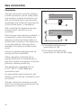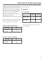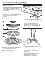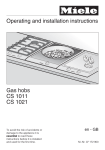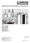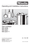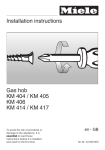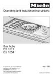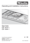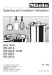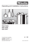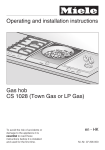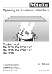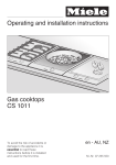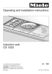
1
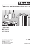
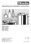
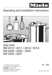
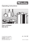
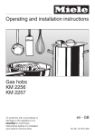
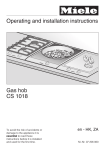
Operating and installation instructions
Gas hobs
CS 1011
CS 1021
To avoid the risk of accidents or
damage to the appliance it is
essential to read these
instructions before it is installed
and used for the first time.
en - GB
M.-Nr. 07 172 900
D Das Gerät ist auch für den Gebrauch in anderen als auf dem Gerät
angegebenen Bestimmungsländer zugelassen. Die landesspezifische
Ausführung und die Anschlussart des Gerätes haben wesentlichen Einfluss auf
den einwandfreien und sicheren Betrieb. Für den Betrieb in einem anderen als
auf dem Gerät angegebenen Bestimmungsland wenden Sie sich bitte an den
für das Land zuständigen Kundendienst.
E El aparato está autorizado para el uso en países diferentes a los países de
destino indicados. La ejecución específica para cada país y el tipo de
conexión del aparato influyen de forma decisiva en el funcionamiento correcto
y seguro. Para el funcionamiento en un país diferente al país de destino
indicado en el aparato, consulte al Servicio Post-venta autorizado para el país.
F Cet appareil est également homologué dans des pays différents de ceux
mentionnés sur l’appareil. Pour que l’appareil fonctionne parfaitement et en
toute sécurité, il est important de disposer de l’exécution spécifique au pays et
du type de raccordement approprié. Pour le fonctionnement dans un pays
autre que celui spécifié sur l’appareil, veuillez vous adresser au service
après-vente du pays où sera installé l’appareil.
G This appliance can be used in countries other than those specified on the
appliance. It is, however, set up for connection to the gas and electricity
supplies in the countries specified. For use in other countries please contact
the Miele spare parts or customer service department in your country.
I L’apparecchio può essere usato anche in paesi diversi da quello indicato
sull’apparecchio stesso. Tuttavia, le varianti specifiche di un determinato paese
e il tipo di allacciamento alla rete hanno un’importanza fondamentale per il suo
sicuro e corretto funzionamento. Per questo se si vuole usare l’apparecchio in
un paese diverso rivolgersi al servizio di assistenza tecnica Miele del paese in
cui si intende usarlo.
M Het apparaat is ook toegelaten voor gebruik in andere landen dan de landen
die op het apparaat vermeld staan. De specifieke uitvoering en de aansluitwijze
zijn van groot belang voor het goed en veilig functioneren. Neem daarom
contact op met de Technische Dienst van de fabrikant in uw land als u het
apparaat in een land wilt gebruiken dat niet op het apparaat vermeld staat.
2
Gas-heated appliances
Safety precautions to take if you smell gas
ß Turn off the gas emergency control valve immediately.
This is usually located near the gas meter.
ß Eliminate all sources of ignition in a safe manner.
Do not smoke, light cigarette lighters or matches.
ß Do not operate electrical lights or switches, i.e. do not switch them "On" or "Off".
ß Open all doors and windows to ventilate the area.
ß If the smell of gas persists, evacuate the building.
In the UK you must now:
ß Call the Gas Emergency Contact Centre (Tel: 0 800 111 999)
For any gas work in the UK always use a Gas Safe registered engineer.
In other countries please follow relevant country specific procedures on gas.
3
Contents
Guide to the appliance . . . . . . . . . . . . . . . . . . . . . . . . . . . . . . . . . . . . . . . . . . . . . 6
CS 1011 . . . . . . . . . . . . . . . . . . . . . . . . . . . . . . . . . . . . . . . . . . . . . . . . . . . . . . . . . . 6
CS 1021 . . . . . . . . . . . . . . . . . . . . . . . . . . . . . . . . . . . . . . . . . . . . . . . . . . . . . . . . . . 7
Accessories supplied . . . . . . . . . . . . . . . . . . . . . . . . . . . . . . . . . . . . . . . . . . . . . . . 9
Warning and safety instructions . . . . . . . . . . . . . . . . . . . . . . . . . . . . . . . . . . . . 10
Caring for the environment . . . . . . . . . . . . . . . . . . . . . . . . . . . . . . . . . . . . . . . . . 16
Before using for the first time. . . . . . . . . . . . . . . . . . . . . . . . . . . . . . . . . . . . . . . 17
Operation . . . . . . . . . . . . . . . . . . . . . . . . . . . . . . . . . . . . . . . . . . . . . . . . . . . . . . . 18
Rapid ignition system . . . . . . . . . . . . . . . . . . . . . . . . . . . . . . . . . . . . . . . . . . . . . . 18
Switching on, adjusting the flame and switching off . . . . . . . . . . . . . . . . . . . . . . . 18
In-operation indicator and Residual heat indicator . . . . . . . . . . . . . . . . . . . . . . . . 20
Pans . . . . . . . . . . . . . . . . . . . . . . . . . . . . . . . . . . . . . . . . . . . . . . . . . . . . . . . . . . . 21
Wok ring . . . . . . . . . . . . . . . . . . . . . . . . . . . . . . . . . . . . . . . . . . . . . . . . . . . . . . 22
Safety features . . . . . . . . . . . . . . . . . . . . . . . . . . . . . . . . . . . . . . . . . . . . . . . . . . . 23
Cleaning and care . . . . . . . . . . . . . . . . . . . . . . . . . . . . . . . . . . . . . . . . . . . . . . . . 24
General notes . . . . . . . . . . . . . . . . . . . . . . . . . . . . . . . . . . . . . . . . . . . . . . . . . . . . 24
Stainless steel surfaces . . . . . . . . . . . . . . . . . . . . . . . . . . . . . . . . . . . . . . . . . . . . . 25
Pan support, control knob . . . . . . . . . . . . . . . . . . . . . . . . . . . . . . . . . . . . . . . . . . . 25
Burner . . . . . . . . . . . . . . . . . . . . . . . . . . . . . . . . . . . . . . . . . . . . . . . . . . . . . . . . . . 26
Problem solving guide . . . . . . . . . . . . . . . . . . . . . . . . . . . . . . . . . . . . . . . . . . . . 27
Optional accessories . . . . . . . . . . . . . . . . . . . . . . . . . . . . . . . . . . . . . . . . . . . . . . 29
Safety instructions for installation . . . . . . . . . . . . . . . . . . . . . . . . . . . . . . . . . . . 30
Appliance and building-in dimensions . . . . . . . . . . . . . . . . . . . . . . . . . . . . . . . 34
CS 1011 . . . . . . . . . . . . . . . . . . . . . . . . . . . . . . . . . . . . . . . . . . . . . . . . . . . . . . . . . 34
CS 1021 . . . . . . . . . . . . . . . . . . . . . . . . . . . . . . . . . . . . . . . . . . . . . . . . . . . . . . . . . 35
4
Contents
Preparing the worktop . . . . . . . . . . . . . . . . . . . . . . . . . . . . . . . . . . . . . . . . . . . . . 36
Installation of several appliances. . . . . . . . . . . . . . . . . . . . . . . . . . . . . . . . . . . . 37
Fitting the spring clamps and spacer bars . . . . . . . . . . . . . . . . . . . . . . . . . . . . 39
Installing / removing the appliance(s) . . . . . . . . . . . . . . . . . . . . . . . . . . . . . . . . 41
General installation tips . . . . . . . . . . . . . . . . . . . . . . . . . . . . . . . . . . . . . . . . . . . 42
Electrical connection . . . . . . . . . . . . . . . . . . . . . . . . . . . . . . . . . . . . . . . . . . . . . . 43
Gas connection . . . . . . . . . . . . . . . . . . . . . . . . . . . . . . . . . . . . . . . . . . . . . . . . . . 45
Conversion to another type of gas. . . . . . . . . . . . . . . . . . . . . . . . . . . . . . . . . . . 47
Jet table . . . . . . . . . . . . . . . . . . . . . . . . . . . . . . . . . . . . . . . . . . . . . . . . . . . . . . . . . 47
Changing the jets. . . . . . . . . . . . . . . . . . . . . . . . . . . . . . . . . . . . . . . . . . . . . . . . . . 48
To change the main jet . . . . . . . . . . . . . . . . . . . . . . . . . . . . . . . . . . . . . . . . . . . 48
To change the small jets. . . . . . . . . . . . . . . . . . . . . . . . . . . . . . . . . . . . . . . . . . 51
Function test . . . . . . . . . . . . . . . . . . . . . . . . . . . . . . . . . . . . . . . . . . . . . . . . . . . . . 52
After sales service, data plate . . . . . . . . . . . . . . . . . . . . . . . . . . . . . . . . . . . . . . 53
5
Guide to the appliance
CS 1011
a Wok burner
b Pan support
c Control knob
d Display
Display
e In-operation indicator
f Residual heat indicator
6
Guide to the appliance
CS 1021
a Wok burner
b Pan support
c Control knob
d Display
Display
e In-operation indicator
f Residual heat indicator
7
Guide to the appliance
Burner
g Inner burner cap
h Outer burner cap
i Burner ring
j Burner head
k Ignition safety device
l Ignitor
m Burner base
8
Guide to the appliance
Accessories supplied
The accessories supplied with your CombiSet appliance as well as a range of
optional ones are available to order (see "Optional accessories").
Wok ring
The Wok ring can be used in instances
where extra stability is required. It is
particularly suitable for woks with a
rounded base.
Small pan ring
This ring provides stability for small
pans.
9
Warning and safety instructions
Correct application
This appliance complies with all
relevant local and national safety
requirements. Improper use can,
however, present a risk of both
personal injury and material
damage.
~ This gas hob is not designed for
commercial use. It is intended for use in
domestic households and in similar
working and residential environments
such as:
– Shops
To avoid the risk of accidents and
damage to the appliance, please
read these instructions carefully
before installation and using it for
the first time. They contain important
notes on installation, safety,
operation and care.
Keep these instructions in a safe
place and ensure that new users are
familiar with the content. Pass them
on to any future owner.
– Offices and showrooms
and by residents in establishments
such as:
– Hostels and guest houses.
~ The gas hob is intended for
domestic use only to cook food and
keep it warm.
Any other use is not supported by the
manufacturer and could be dangerous.
Miele cannot be held liable for damage
resulting from incorrect or improper use
or operation of the appliance.
~ This appliance is not intended for
use by persons (including children)
with reduced physical, sensory or
mental capabilities, or lack of
experience and knowledge, unless they
are supervised whilst using it, or have
been shown how to use it by a person
responsible for their safety.
10
Warning and safety instructions
Safety with children
~ This appliance is only intended for
use by adults who have read these
instructions. This appliance is not a toy!
To avoid the risk of injury, keep children
well away and do not allow them to play
with it or use the controls. They will not
understand the potential dangers
posed by it. They should be supervised
whenever you are working in the
kitchen.
~ Packaging, e.g. cling film,
polystyrene and plastic wrappings,
must be kept out of the reach of babies
and young children. Danger of
suffocation. Dispose of or recycle all
packaging safely as soon as possible.
~ Older children may use the
appliance only when its operation has
been clearly explained to them and
they are able to use it safely,
recognising the dangers of misuse.
~ The appliance gets hot when in use
and remains hot for quite a while after it
has been switched off. To safeguard
against burning, keep children well
away from the appliance at all times.
~ Do not store anything which might
arouse a child's interest in storage
areas above or next to the hob.
Otherwise they could be tempted into
climbing onto the appliance with the
risk of burning themselves.
~ Keep all pans out of reach of
children. Turn pan handles inwards
away from the edge of the hob. Danger
of burning or scalding.
11
Warning and safety instructions
Technical safety
~ Before installation, check the
appliance for visible signs of damage.
Under no circumstances should you
use a damaged appliance. It could be
dangerous.
~ The electrical safety of this
appliance can only be guaranteed
when continuity is complete between it
and an effective earthing system which
complies with current local and national
safety regulations. It is most important
that this basic safety requirement is
present and tested regularly, and
where there is any doubt, the
household wiring system should be
inspected by a qualified electrician.
Miele cannot be held liable for the
consequences of an inadequate
earthing system (e.g. electric shock).
~ Before connecting the appliance to
the mains supply, make sure that the
data quoted on the data plate match
the household mains supply, otherwise
the appliance could be damaged.
Consult a qualified electrician if in any
doubt.
~ Connection to the gas supply must
be carried out by a suitably qualified
and competent person in strict
accordance with current local and
national safety regulations, e.g. a Gas
Safe registered technician in the U.K.
12
~ If the appliance is supplied without a
plug, or if the plug is removed, it must
be connected to the mains electricity
supply by a suitably qualified and
competent electrician in strict
accordance with current local and
national safety regulations. The
manufacturer cannot be held liable for
damage caused by incorrect
installation or connection.
~ For safety reasons, this appliance
may only be used when it has been
built in.
~ Never open the outer casing of the
appliance. Tampering with electrical
connections or components and
mechanical parts is highly dangerous
to the user and can cause operational
faults.
~ Installation, maintenance and
repairs may only be carried out by a
suitably qualified and competent
person in strict accordance with current
national and local safety regulations.
Repairs and other work by unqualified
persons could be dangerous. The
manufacturer cannot be held liable for
unauthorised work.
Warning and safety instructions
~ During installation, maintenance and
repair work, the appliance must be
connected from the gas supply and
mains electricity supply.
~ While the appliance is under
guarantee, repairs should only be
undertaken by a service technician
authorised by Miele. Otherwise the
guarantee is invalidated.
~ Faulty components must only be
replaced by genuine Miele original
spare parts. The manufacturer can only
guarantee the safety of the appliance
when Miele replacement parts are
used.
~ Do not use the hob if it is faulty.
Switch it off immediately and
disconnect it from the mains electricity
supply and the gas supply. Call the
Service Department.
~ In countries where there are areas
which may be subject to infestation by
cockroaches or other vermin, pay
particular attention to keeping the
appliance and its surroundings in a
clean condition at all times. Any
damage caused by cockroaches or
other vermin will not be covered by the
guarantee.
~ If the connection cable is damaged,
it must be replaced by a suitably
qualified electrician with a special
connection cable of type H 05 V V-F
(pvc insulated), available from the Miele
Spare Parts Department.
~ Do not connect the appliance to the
mains electricity supply by a
multi-socket unit or an extension lead.
These do not guarantee the required
safety of the appliance (e.g. danger of
overheating).
13
Warning and safety instructions
Correct use
~ The appliance gets hot when in use
and remains hot for quite a while after it
has been switched off. Do not touch it
whilst it could still be hot.
~ If a cooker hood is installed above
the gas hob, ensure that the burners
are always covered with a pan when in
use. Otherwise flames could reach the
cooker hood, parts of which could then
be damaged or set on fire.
~ Do not leave the appliance
unattended whilst it is being used. Oil
and fat are potential fire hazards as
they can ignite if overheated.
~ If oil or fat does catch fire, do not
attempt to put out the flames with water.
Use a suitable fire blanket, saucepan
lid, damp towel or similar to smother the
flames.
~ Do not flambé under a cooker hood.
The flames could set the cooker hood
on fire.
~ Do not use the appliance as a
resting place for anything else. The
article could melt or catch fire if
residual heat is still present or if the
appliance is switched on by mistake.
~ Where several appliances are
installed side by side
Do not place hot pots or pans on the
joining strip as this can damage the
seal.
~ Do not cover the appliance, e.g.
with a cloth, kitchen foil, etc. This could
be a fire hazard if the hob were
switched on by mistake.
~ Do not use plastic or aluminium foil
containers. These melt at high
temperatures and could catch fire.
~ Do not use the appliance to heat up
the room. Due to the high temperatures
radiated, objects near the appliance
could catch fire. The life of the
appliance could also be reduced.
~ Do not heat up unopened tins of
~ Always use heat-resistant pot
holders or gloves when working with a
hot appliance. Ensure that they do not
come into contact with the flames. Do
not use large cloths, tea towels or
similar as the ends could touch the
flames and catch fire. Take care not to
let the gloves get damp or wet, as this
causes heat to transfer through the
material more quickly with the risk of
scalding or burning yourself.
~ Make sure all the components of the
14
food on the hob as pressure will build
up in the tin, causing it to explode. This
could result in injury and scalding or
damage.
gas burners have been correctly
assembled before switching on.
~ Pans must be the correct size for the
burner they are used on (see "Suitable
pans"). A pan which is too small will be
unstable on the pan support. If the pan
diameter is too large, flames can
spread out to the sides and damage or
burn the worktop, wall claddings or
surrounding units and also parts of the
hob. Miele cannot be held liable for this
type of damage.
Warning and safety instructions
~ Ensure that the flames from the
burner do not spread out beyond the
base and up the sides of the pan.
~ Unless the pan manufacturer states
that you can do so, do not use pans
with very thin bases on this hob, and
never heat up empty pans as they
could get damaged. This could also
damage the appliance.
~ The pan support supplied must
always be used. Pans must not be
placed directly on the burner.
~ Do not store any inflammable
objects near the gas hob.
~ Remove splashes of fat and other
food debris from the surface as soon as
possible. These are a fire hazard.
~ Replace the pan supports carefully
to avoid scratching the surface of the
hob.
~ Using the gas hob will cause a
build-up of heat and moisture in the
room in which it is installed. Ensure that
the room has sufficient natural or
mechanical means of ventilation, e.g.
an extractor.
~ If the hob is used for very long
periods of time additional ventilation of
the room may be necessary, e.g. by
opening windows or doors, or running
the extractor on the highest setting.
~ When using an electrical appliance,
e.g. a hand-held food blender, near the
gas hob, ensure that the cable of the
electrical appliance does not come into
contact with the hot appliance. The
insulation on the cable could become
damaged, giving rise to an electric
shock hazard.
~ Spray canisters, aerosols and other
inflammable substances must not be
stored in a drawer under the hob.
Cutlery inserts must be heat-resistant.
~ Always ensure that food is
sufficiently cooked or reheated. Many
factors will affect the overall cooking
time, including the size and amount of
food and its temperature. Some foods,
e.g. poultry, may contain
micro-organisms which are only
destroyed by thorough cooking at a
sufficiently high temperature for long
enough. If in doubt, select a longer
cooking or reheating time.
~ Avoid allowing liquids or foods
containing salt to spill onto the hob. If
salty foods or liquids do get on the hob,
they should be removed as soon as
possible to avoid the risk of corrosion.
~ If the hob is installed behind a
kitchen furniture door, it may only be
used with the furniture door open.
Only close the door when the appliance
is switched off and the residual heat
indicators have gone out.
~ If the appliance has not been used
for a long period of time it should be
thoroughly cleaned before it is used
again. It is also advisable to have the
appliance tested for safety.
~ This appliance must not be set up or
operated in the open air.
Miele cannot be held liable for
damage caused by non-compliance
with these Warning and safety
instructions.
15
Caring for the environment
Disposal of the packing
material
The transport and protective packing
has been selected from materials which
are environmentally friendly for
disposal, and should be recycled.
Ensure that any plastic wrappings,
bags, etc. are disposed of safely and
kept out of the reach of babies and
young children. Danger of suffocation.
Disposal of your old appliance
Electrical and electronic appliances
often contain materials which, if
handled or disposed of incorrectly,
could be potentially hazardous to
human health and to the environment.
They are, however, essential for the
correct functioning of your appliance.
Please do not therefore dispose of it
with your household waste.
Please dispose of it at your local
community waste collection/recycling
centre or contact your Dealer for
advice. Ensure that it presents no
danger to children while being stored
for disposal.
16
Before using for the first time
Please stick the extra data plate for the
appliance supplied with this
documentation in the space provided in
the "After sales service" section of this
booklet.
Cleaning for the first time
^ Remove any protective foil and
stickers.
^ Clean all removable parts of the
burners with a solution of warm water
and a little washing-up liquid applied
with a soft sponge. Dry all parts
thoroughly after cleaning and then
reassemble the burners (see
"Cleaning and care").
^ Clean the stainless steel trough with
a damp cloth, and then wipe dry.
Metal components have a protective
coating which may give off a slight
smell when heated up for the first
time.
The smell and any vapours will
dissipate after a short time, and do
not indicate a faulty connection or
appliance.
17
Operation
Rapid ignition system
The appliance has a rapid ignition
system with the following features:
– Rapid ignition without pressing und
holding the control
– Automatic re-iginition
Should the flame be extinguished by
a gust of air, the burner will re-ignite
automatically.
If re-ignition is unsuccessful, the gas
supply will be cut off automatically
(see "Safety cut-off").
The burner can only be switched on
by pressing in the control and
turning it anti-clockwise. It is
switched off by turning the control
clockwise. The outer flame ring can
only be switched on and off by
pressing down on the control and
turning it the appropriate way.
The following will cause damage to
the appliance:
-
Switching the burner on without
pressing the control down,
Switching on, adjusting the
flame and switching off
-
Switching the burner on by
turning the control clockwise,
The control is used to ignite the burner
and to regulate the strength of the
flame.
-
Switching the outer flame ring
on or off without pressing the
control down,
-
Switching the burner off by
turning the control
anti-clockwise.
ß The gas supply is turned off
& Strongest flame
Both the inner and the outer burners
operate on full output.
& (2x) Strong flame
The outer burner operates on low
output and the inner burner on high
output.
/ Weak flame
The outer burner is switched off, and
the inner burner operates on high
output.
/ Weak flame
The outer burner is switched off,
The inner burner operates on low
output.
18
The manufacturer will not accept
liability for any damage resulting
from incorrect operation.
Operation
Switching on
^ To ignite the burner press the control
knob down and turn it anti-clockwise
to the large flame symbol. The ignitor
will make a clicking sound and ignite
the gas.
Operating a control will automatically
create a spark on every burner. This
is quite normal and does not indicate
a fault.
If the burner does not ignite, turn the
control to off "ß". Air the room or wait at
least 1 minute before trying again.
If the burner does not ignite the second
time, turn the control to "ß", and see
"Problem solving guide".
When switching on, re-ignition
sometimes occurs (1-2 clicks) if the
flame on the ignition safety device has
gone out briefly, or if the thermal
element is not hot enough, e.g.
following a gust of air.
Regulating the flame
Control the flame so that it does not
spread out beyond the sides of the
pan. As the outer part of the flame is
much hotter than the centre, the tips of
the flames should stay beneath the pan
base. Flame tips which extend beyond
the sides of the pan merely warm up
the air in the room and can also
damage pan handles and increase the
risk of injury.
^ To switch from a high to a low setting,
turn the control anti-clockwise until it
meets resistance within range a as
shown. Press in the control, then turn
it past the resistance and release it.
You can now select the setting you
require.
^ To switch from a low to a high setting,
turn the control clockwise until it
meets resistance within range b as
shown. Press in the control, then turn
it past the resistance and release it.
You can now select the setting you
require.
Switching off
^ Turn the control clockwise to position
"ß".
This stops the flow of gas and the flame
goes out.
19
Operation
In-operation indicator and
Residual heat indicator
When the gas hob is switched on, the
in-operation indicator lights up. Once it
has reached a certain temperature, the
residual heat indicator also lights up.
The in-operation indicator goes out
when the gas hob is switched off. The
residual heat indicator remains on until
the gas hob is cool enough to touch.
Do not touch or place any heat
sensitive objects on the gas hob
while the residual heat indicator is
still on. Danger of burning and fire.
If the display is flashing, this shows
there is a fault. See section "Problem
solving guide".
20
Pans
Min. base diameter
Pots / pans = 15 cm
Max. rim diameter
Pots / pans = 28 cm
– Wide, shallow pans are preferable to
tall, narrow ones. They will heat up
faster.
– Pans with thick bases are preferable
as these distribute heat more evenly.
With thin bases, there is a danger of
food overheating in places. Stir the
food frequently.
– Position the pan centrally on the pan
support so that it sits securely and
cannot tip up. A little movement is
quite normal and not a cause for
concern.
– Use the correct sized pans for your
appliance. A pan which is too small
will be unstable on the pan support.
If the pan diameter is too large,
flames can spread out to the sides
and damage or burn the worktop,
wall claddings or surrounding units
and also parts of the hob. The
manufacturer cannot be held liable
for this type of damage.
– Any heat-resistant pans can be used
on a gas burner.
– Remember when purchasing new
pans that manufacturers usually refer
to the diameter at the top of the pan
in their documentation.
– Use a lid whenever possible to
minimise heat loss.
– The pan support supplied with the
appliance must always be used.
Never place a pan on the burner
itself.
21
Pans
Wok ring
Small pan ring
Use the small pan ring supplied when
cooking with a small pan. The ring
allows the pan to sit securely and
prevents it from tipping.
Use the wok ring supplied to give
additional stability, especially to woks
with a rounded base.
Woks: Woks have a small base
diameter and large top diameter,
generally between 35 - 40 cm.
Make sure that the wok ring is located
securely in its correct position. See
illustration.
22
Safety features
Thermo-electric ignition
Safety cut-out
This appliance has a thermo-electric
ignition safety device. If the flame goes
out, for example if food has boiled over
or if there is a sudden draught, and
automatic re-ignition has been
unsuccessful, the supply of gas to the
burner will be cut off.
If a burner has been used for an
unusually long period (approx. 4
hours), it will switch off automatically.
To use the burner again, turn the
control clockwise to the "ß" position,
and then switch it back on as normal.
^ To use the burner again, turn the
control clockwise to the "ß" position,
and then switch it back on as normal.
23
Cleaning and care
General notes
,Under no circumstances use a
steam cleaning appliance to clean
this appliance. The steam could
reach the electrical components and
cause a short circuit.
The appliance should be cleaned after
each use. Let it cool down to room
temperature.
To avoid water marks and limescale
deposits use a soft cloth to dry surfaces
that have been cleaned with water.
Cooked food which spills over onto the
hot appliance can cause discolouration
of the burner components and the
stainless steel surface. Remove any
soiling immediately.
To avoid damaging the surface or
your hob, do not use:
– cleaning agents containing soda,
alkaline, ammonia, acids or
chlorides,
– cleaning agents containing
descaling agents,
– stain or rust removers,
– abrasive cleaning agents, e.g.
powder cleaners and cream
cleaners,
– solvent-based cleaning agents,
– dishwasher cleaner,
– grill and oven cleaners,
– glass cleaning agents,
– hard, abrasive brushes or sponges,
e.g. pot scourers, brushes or
sponges which have been previously
used with abrasive cleaning agents,
– sharp pointed objects
(these can damage the seal between
the frame and the worktop).
24
Cleaning and care
Stainless steel surfaces
Pan support, control knob
Clean stainless steel surfaces using an
E-Cloth or with a solution of warm water
and a little washing-up liquid applied
with a soft sponge. In the case of
stubborn dried-on soiling, soak first.
Finally, dry with a soft cloth.
Remove the pan support. Clean the
pan support and the control knob with a
solution of warm water and a little
washing-up liquid applied with a soft
sponge. Stubborn soiling should be
soaked first.
If necessary a cleaning agent for
ceramic and stainless steel surfaces
can be used (see "Optional
accessories"). Apply with even
pressure following the direction of the
"grain".
After cleaning dry all surfaces with a
clean cloth.
Do not clean the pan supports in a
dishwasher.
A conditioning agent for stainless steel
can be used after cleaning to help keep
your appliance looking good (see
"Optional accessories").
Apply sparingly with a soft cloth
following the instructions on the
packaging.
Printed surfaces (Flame symbols)
Remove any soiling which comes
into contact with the printed flame
symbols straight away. Soiling,
particularly salty food or liquid and
olive oil, can cause damage if left on
the printed surfaces for a long time.
Do not use stainless steel cleaning
agents on the printed flame
symbols. This would rub off the print.
25
Cleaning and care
Burner
Reassemble the burner
Do not clean any parts of the burner
in a dishwasher.
The burner should be dismantled and
then cleaned by hand using a solution
of warm water and a little washing-up
liquid applied with a soft sponge.
Parts of the burner that cannot be
removed should be wiped clean with a
damp cloth only.
The ignitor and ignition safety device
should be very carefully wiped clean
using a well wrung out cloth.
Do not let the ignitor get wet. If it gets
wet it will not spark.
After cleaning dry all surfaces with a
clean cloth.
Make sure that the flame slits are clean
and completely dry.
The surfaces of the two burner caps
will become more matt with time. This
is quite normal and will not affect the
operation of the hob.
After cleaning the burner it must be
reassembled in the correct order.
^ Place burner head j on to burner
base m so that the the ignition safety
device k and the ignitor l extend
through their respective holes in the
burner head. The burner head must
click into place correctly.
^ Place burner ring i in position.
^ The place burner cap g and h in
position.
26
Problem solving guide
,Repairs to the gas and electrical
components of this appliance must
only be carried out by a suitably
qualified and competent person to
ensure safety (Gas Safe registered
in the UK). Repairs and other work
by unqualified persons could be
dangerous. The manufacturer
cannot be held liable for
unauthorised work.
What to do if ...
... the burner does not ignite when
the hob is being used for the first
time or after a long period of not
being used.
There could be air lock in the gas pipe.
You may need to make several
attempts before the burner ignites
successfully.
... the in-operation and residual heat
indicators are flashing at the same
time.
Both indicators will flash after an
interruption to the power supply.
Turn all the controls clockwise to
position "ß". You can then operate the
appliance as normal.
... the in-operation indicator is
flashing.
There is no supply of gas.
Turn all the controls clockwise to
position "ß". You can then operate the
appliance as normal.
If the problem persists, disconnect the
appliance from the electricity supply for
a few seconds.
... the burner does not ignite after
several attempts.
Disconnect the appliance from the
electricity supply for a few seconds. If
the problem persists, check whether
– the burner is correctly assembled.
– the gas supply tap is turned on.
– the burner is dry and clean.
– the flame slits are dry and
unblocked.
... the gas flame goes out after being
lit.
The flames need to touch the ignition
safety device so that it heats up
sufficiently.
If the flames do not touch the ignition
safety device, check that
– the burner components are
assembled correctly.
– there is no soiling on the ignition
safety device. If there is, remove it
carefully (see "Cleaning and care").
27
Problem solving guide
... the gas flame suddenly looks
different.
Check whether the burner components
are assembled correctly.
... the gas flame goes out during
operation.
Check whether the burner components
are assembled correctly.
.... the ignitor on the burner does not
spark.
Check whether
– the mains fuse has tripped. If it has,
contact a qualified electrician or the
Miele Service Department.
– food deposits have lodged
themselves between the ignitor and
the burner cap.
Remove any food deposits carefully
(see "Cleaning and care").
– food deposits have lodged
themselves on the ignition safety
device.
Remove any food deposits carefully
(see "Cleaning and care").
For safety reasons you may not be
able to re-ignite the burner for about
5 minutes after a spillage.
28
Optional accessories
Miele branded cleaning and conditioning products are
available for your appliance.
These can be ordered via the internet on
www.miele-shop.com or from the Miele Spare Parts
Department (see back cover) or from your Miele dealer.
Ceramic and stainless steel hob cleaner 250 ml
Removes heavy soiling, limescale deposits and light
discolouration
Stainless steel conditioning agent 250 ml
Removes water marks, flecks and finger prints.
Helps keep the hob looking good for longer.
E-Cloth (microfibre cloth)
Removes finger marks and light soiling.
29
Safety instructions for installation
This appliance must be installed and
connected to services in
accordance with local and national
safety and building regulations.
Fit wall units and extractor hood
before fitting the hob to avoid
damaging the surface.
~ The room in which the gas hob is
installed must be at least 20 m3 in size
with a door or window in it which can
be opened to the outside air.
~ The veneer or laminate coatings of
worktops (or adjacent kitchen units)
must be treated with 100 °C
heat-resistant adhesive which will not
dissolve or distort.
Any backmoulds must be of
heat-resistant material.
~ This appliance may only be used in
mobile installations such as ships if a
risk assessment of the installation has
been carried out by a suitably qualified
engineer.
~ An electric fryer must not be
installed directly next to a gas hob, as
the gas flames could ignite the fat in the
fryer. It is essential to maintain a
distance of at least 288 mm between
these two appliances.
~ A gas hob may not be built in over a
fridge, fridge freezer, freezer,
dishwasher, washing machine or
tumble dryer.
~ It can be installed above an oven.
The worktop must be at least 40 mm
thick.
30
~ Ensure that the gas pipe and
electrical cable are installed in such a
way that they do not touch any parts of
the appliance which become hot. This
could cause damage.
~ The electrical cable and any flexible
gas connection pipes must be installed
in such a way so that they do not come
into contact with any moving kitchen
parts (e.g. a drawer), and cannot
become trapped.
~ Spray canisters, aerosols and other
inflammable substances should not be
stored in a drawer under the hob.
Cutlery inserts must be heat-resistant.
~ Observe carefully the safety
distances given on the following pages.
All dimensions in this instruction booklet
are given in mm.
Safety instructions for installation
Safety distance above the hob
A minimum safety distance must be
maintained between this appliance and
the cooker hood above it. See the
cooker hood manufacturer's operating
and installation instructions for details.
If the manufacturer's instructions are
not available for the cooker hood, a
minimum safety distance of at least
760 mm must be maintained. For any
flammable objects, e.g. utensil rails,
wall units etc. a minimum distance of at
least 760 mm must be maintained
between them and the appliance
below.
When two or more appliances are
installed together below a cooker hood,
e.g. an electric hob and a gas wok
combiset, which have different safety
distances given in their installation
instructions you should select the
greater distance of the two.
31
Safety instructions for installation
Safety distances to the sides of the
hob
Ideally the hob should be installed with
plenty of space on either side. There
may be a wall at the rear and a tall unit
or wall at one side. On the other side,
however, no unit or divider should
stand higher than the hob (see
illustrations).
Due to the high temperatures radiated
by the hob, it is essential that a
minimum distance of 50 mm is
maintained between the worktop
cut-out and the back wall.
recommended
The minimum distance a between the
worktop cut-out and a wall or tall unit to
the right or left of it is:
40 mm
for
CS 1212
CS 1221
CS 1234
CS 1223
50 mm
for
CS 1112
CS 1122
CS 1134
CS 1326
CS 1411
100 mm for
CS 1012
CS 1013
150 mm for
CS 1421
CS 1312
CS 1322
200 mm for
CS 1034
250 mm for
CS 1011
CS 1018
CS 1021
32
not recommended
not allowed
Safety instructions for installation
Safety distance when installing the appliance near a wall with additional
niche cladding
A minimum safety distance must be maintained between the worktop cut-out and
any niche cladding to protect it from heat damage.
If the niche cladding is made from a combustible material (e. g. wood) a
minimum safety distance e of 50 mm must be maintained between the cut-out
and the cladding.
If the niche cladding is made from a non-combustible material (e. g. metal,
natural stone, ceramic tiles) a minimum safety distance e of 50 mm less the
thickness of the cladding must be maintained between the cut-out and the
cladding.
Example: 15 mm niche cladding
50 mm - 15 mm = minimum safety distance of 35 mm
a Masonry
b Niche cladding
Dimension x = thickness of niche cladding material
c Worktop
d Worktop cut-out
e Minimum safety distance
for combustible materials is 50 mm
for non-combustible materials is 50 mm less dimension x
33
Appliance and building-in dimensions
CS 1011
a Spring clamps
b Front
c Building-in depth
d Building-in depth for the mains connection box with mains connection cable,
L = 2000 mm
e Building-in depth for the gas connection R 1/2 - ISO 7-1 (DIN 2999)
34
Appliance and building-in dimensions
CS 1021
a Spring clamps
b Front
c Building-in depth
d Building-in depth for the mains connection box with mains connection cable,
L = 2000 mm
e Building-in depth for the gas connection R 1/2 - ISO 7-1 (DIN 2999)
35
Preparing the worktop
^ Make the worktop cut-out for one or
more appliances as applicable.
Remember to maintain the minimum
safety distance from the back wall,
as well as from any tall unit or side
wall to the right or left of the hob.
See "Safety instructions for
installation".
^ Seal the cut surfaces with a suitable
heat-resistant sealant to avoid
swelling caused by moisture.
The materials used must be
heat-resistant.
If, during installation, you find that the
seals on the corners of the frame are
not flush with the worktop surface,
the corner radius (ß R4) can be
carefully scribed to fit.
36
Installation of several appliances
When installing two or more appliances next to each other a spacer bar b must
be used between each one.
See “Fixing the spring clamps and spacer bars”.
Worktop cut-out
- two appliances
Worktop cut-out
- three appliances
To calculate the cut-out width (D) required:
Add up the widths of each appliance (e.g. width A + B + C etc.) and subtract
16 mm from this figure
(i.e. 8 mm is taken off either end of the appliance run).
Number of
appliances
Appliance width in mm Worktop cut-out in mm
1
288
288 - 16 = 272
2
288, 288
288 + 288 - 16 = 560
2
288, 380
288 + 380 - 16 = 652
3
288, 288, 288
288 + 288 + 288 - 16 = 848
3
288, 288, 380
288 + 288 + 380 - 16 = 940
37
Installation of several appliances
a Spring clamps
b Spacer bars
c Gap between spacer bar and worktop
d Sealing strip
The illustration shows a worktop cut-out with spring clamps a and spacer bars b
for 3 appliances.
An additional spacer bar is required for each additional appliance. The position
for securing each additional spacer bar will depend on the width of appliance B
(288 mm / 380 mm / 576 mm).
38
Fitting the spring clamps and spacer bars
Wooden worktops
Granite and marble worktops
The screws are not required for
granite or marble worktops.
^ Position the spring clamps supplied
a and spacer bars b on the top
edge of the cut-out in the positions
marked.
^ Secure the spring clamps and
spacer bars with the 3.5 x 25 mm
screws supplied.
^ Position and secure the spring
clamps a and spacer bars b using
strong, double-sided adhesive
tape c.
39
Fitting the spring clamps and spacer bars
^ Apply silicone to the side edges and
the lower edges of the spring
clamps a and the spacer bars b.
^ Then fill gap e between the spacer
bars and the worktop with silicone
from the tube supplied.
40
Installing / removing the appliance(s)
Installing the appliance(s)
^ Feed the connection cable down
through the cut-out.
^ Starting at the front, position the
appliance in the worktop cut-out.
^ Using both hands, press down
evenly on the sides of the appliance
until it clicks into position. When
doing this make sure that the seal
under the appliance sits flush with
the worktop on all sides. This is
important to ensure an effective seal
all round. Do not use sealant.
When installing several appliances, a
sealing strip must be fitted into each
spacer bar.
^ Starting at the front, position the next
appliance in the worktop cut-out.
^ Connect each appliance to the mains
(see "Electrical connection").
^ Check that each appliance works
correctly.
Removing the appliance
If the appliance is accessible from
below, it can be pushed up and out of
the cut-out. It must be pushed up from
the back first.
If the appliance is not accessible from
below, take hold of the appliance with
both hands at the back, pull it forwards,
then lift it up and out.
^ Push the appliance to the side until
the long slots in the spacer bar can
be seen.
^ Fit the sealing strip d into the long
slots in the spacer bar b.
41
General installation tips
Tiled worktop
Do not use any sealant unless
expressly instructed to do so. The
sealing strip under the edge of the top
part of the appliance provides a
sufficient seal for the worktop.
Do not use sealant between the
frame of the top part of the
appliance and the worktop.
This could cause difficulties if the
appliance ever needs to be taken
out for servicing and possibly result
in damage to the frame or the
worktop.
42
Grout lines a and the hatched area
underneath the appliance must be
smooth and even. If they are not, the
appliance frame will not sit flush with
the worktop and the sealing strip will
not provide a good seal between the
appliance and the worktop.
Electrical connection
All electrical work should be carried
out by a suitably qualified and
competent person, in strict
accordance with current local and
national safety regulations (BS 7671
in the UK).
Installation, repairs and other work
by unqualified persons could be
dangerous. The manufacturer
cannot be held liable for
unauthorised work.
Ensure power is not supplied to the
appliance until after installation or
repair work has been carried out.
The appliance must only be
operated when built-in. This is to
ensure that all electrical parts are
shielded. Live parts must not be
exposed.
Do not connect the appliance to the
mains electricity supply by an
extension lead. These do not
guarantee the required safety of the
appliance.
Connection should be made via a
suitable isolator or a double pole fused
spur connection unit which complies
with national and local safety
regulations and the on/off switch should
be easily accessible after the appliance
has been built in.
If the switch is not accessible after
installation (depending on country) an
additional means of disconnection must
be provided for all poles.
For extra safety it is advisable to protect
the appliance with a suitable residual
current device (RCD).
When switched off there must be an
all-pole contact gap of 3 mm in the
isolator switch (including switch, fuses
and relays).
Important UK
This appliance is supplied for
connection to a single phase 230 V
50 Hz supply with a 3-core cable.
The wires in the mains lead are
coloured in accordance with the
following code:
Green/yellow = earth
Please make sure that the connection
data quoted on the data plate match
the household mains supply.
Blue
= neutral
Brown
= live
WARNING
THIS APPLIANCE MUST BE
EARTHED
43
Electrical connection
Important
The electrical safety of this appliance
can only be guaranteed when
continuity is complete between it and
an effective earthing system, which
complies with current local and national
safety regulations. It is most important
that this basic safety requirement is
present and regularly tested and where
there is any doubt, the electrical wiring
in the home should be tested by a
qualified electrician. The manufacturer
cannot be held liable for the
consequences of an inadequate
earthing system such as an electric
shock.
If the connection cable is damaged, it
must be replaced by a suitably
qualified electrician with a special
connection cable of type H 05 V V-F
(pvc insulated), available from the Miele
Spare Parts Department.
The manufacturer cannot be held
liable for damage which is the direct
or indirect result of incorrect
installation or connection.
44
Gas connection
,Connection to the gas supply, or
conversion from one type of gas to
another, should only be undertaken
by an approved and registered gas
installer in strict accordance with
local and national safety and
building regulations (e.g. Gas Safe
registered in the UK).
Every appliance should have its own
easily accessible isolating valve and
test point.
Check with your local gas supplier
about the type of gas and its
calorific value and compare this
information with the type of gas
quoted on the hob data plate.
This appliance is not connected to
an exhaust flue. Please ensure it has
adequate ventilation after
installation.
Depending on country, the hob is
supplied ready for connection to natural
or liquid gas (refer to label on the
appliance).
United Kingdom:
GB II 2 H 3+ 20 mbar, 28-30/37 mbar
Ireland:
IE II 2 H 3+ 20 mbar, 28-30/37 mbar
Depending on country, a set of jets for
conversion to an alternative type of gas
may be included with the hob.
Please contact your dealer or the Miele
Spare Parts Department for the
appropriate conversion jets if
necessary.
Conversion to another type of gas is
described under "Conversion to another
type of gas".
For any gas work in the UK always
use a Gas Safe registered engineer.
The installer is responsible for
ensuring that the appliance
functions correctly when installed.
45
Gas connection
Connection
The gas connection must be installed
so that connection can be made either
from inside or outside the kitchen unit,
and the isolating valve must be easily
accessible and visible (by opening one
of the kitchen doors, if necessary).
After installing the appliance the gas
burners have to be set for local
conditions.
When the gas hob has been installed, it
is essential to check that neither the
gas pipe not the electricity cable is in
contact with hot parts of the appliance
or hot gas exhaust, otherwise heat
damage to the pipe and cable could
occur.
A test for possible leakages must be
carried out after installation.
Safety regulations demand that a
pressure test point is installed near a
gas hob to allow an engineer to test the
pressure, following servicing.
The appliance is supplied with an
R 1/2" - ISO 7-1 (DIN 2999) gas
connection point.
An appropriate rigid connection and
isolating valve must be installed for final
connection.
The gas connection must be so sited
that it is not adversely heated when the
appliance is in operation.
46
a Connection with test point
specifically for GB
b Connection with test point
specifically for GB and 90° angle
Conversion to another type of gas
,Connection to the gas supply, or
conversion from one type of gas to
another, should only be undertaken
by an approved and registered gas
installer in strict accordance with
local and national safety and
building regulations (e.g. Gas Safe
registered in the UK).
When converting to a different type of
gas, the main burner jets and the small
burner jets have to be changed.
Nominal rating at high setting
Gas type
Natural gas H
Liquid gas
Screw in the new jets according to the
following table.
Jet table
For UK and IE
Main jet
C
Small jet
C
Natural gas H
1.75 /
Nr. 34
0.88 / 0.42
Liquid gas
1.12 /
Nr. 7
0.60 / 0.23
The jet markings refer to 1/100 mm of
the jet diameter.
kW
6.00
5.40 / 394 g/h
Nominal rating at low setting
Gas type
kW
Natural gas H
Liquid gas
0.26
0.26
47
Conversion to another type of gas
Changing the jets
Disconnect the gas hob from the
mains electricity supply. Turn off the
gas supply.
To change the jets, the burner securing
screws must first be loosened and the
upper section of the appliance
removed.
To change the main jet
^ Remove burner covers op, burner
ring q and burner head r.
^ Pull the control knob off.
^ Loosen screws w.
48
^ Carefully remove the upper section of
the appliance. When doing this make
sure you do not also pull out the light
unit for the display a located
underneath the upper section. To
release the unit, squeeze together
the two clamps b.
^ Whilst counterholding it in place with
an SW 13 spanner, unscrew the main
jet anti-clockwise from its housing
using an SW 10 spanner (see
illustration).
^ Screw in the new main jet, once
again using the spanner to
counterhold the jet housing.
Conversion to another type of gas
To change the jet for the inner burner
^ Whilst counterholding in place with
an SW 12 spanner, remove screw c
from screw fitting b using an SW 8
spanner.
^ Whilst counterholding in place with
an SW 12 spanner, remove screw
fitting b from fitting a using another
SW 12 spanner.
^ Remove jet disc d from fitting a,
and replace with the correct jet disc
(see jet table).
^ Adjust air intake sleeve e until the
two vents f have a 2 mm gap, as
illustrated.
^ Reassemble the parts in the reverse
order and check for leaks.
d Jet disc (main jet for the inner
burner)
e Air intake sleeve
f Vent
49
Conversion to another type of gas
To check the first intake of air
a Adjusting screw
b Air intake sleeve
Gap X must measure:
For natural gas: 6 mm
For liquid gas:
13 mm
To set gap X
^ Loosen screw a and adjust air intake
sleeve b. Then retighten screw a.
50
Conversion to another type of gas
To change the small jets
a Small diameter jet
(e.g. for liquid gas: 0.23)
b Large diameter jet
(e.g. for liquid gas: 0.60)
^ Using a small screwdriver, unscrew
the two small jets a and b in the gas
fitting.
^ Pull out the jets with a pair of pliers.
^ Fit the correct jets securely (see jet
table).
^ Finally, secure the jets against
inadvertent loosening with sealing
wax.
51
Conversion to another type of gas
Function test
Check all gas fittings for leaks.
^ Reassemble the appliance.
^ Check the burner flame by operating
the burner.
The flame must not go out on the
lowest setting, or when the control is
turned quickly from a high to a low
setting.
On the highest setting, the flame
must have a distinctive and visible
core.
^ Stick the label supplied with the jets
above the label stating the type of
gas being used.
52
After sales service, data plate
In the event of any faults which you cannot remedy yourself, or if the appliance is
under guarantee, please contact:
– Your Miele dealer, or
– the Miele Customer Contact Centre (see back cover for address).
Please note that telephone calls may be monitored and recorded to improve
our service.
When contacting Miele, please quote the model and serial number of your
appliance which are given on the data plate.
N.B. A call-out charge will be applied for service visits where the problem
could have been resolved as described in these instructions.
Space in which to stick the extra data plate supplied with the appliance. Ensure
that the model number is the same as the one on the front of these instructions.
53
54
55
Alteration rights reserved/ 1610
M.-Nr. 07 172 900 / 10