1
IA261/262 WinCE User’s Manual
Second Edition, April 2009
www.moxa.com/product
© 2009 Moxa Inc. All rights reserved.
Reproduction without permission is prohibited.
IA261/262 WinCE User’s Manual
The software described in this manual is furnished under a license agreement and may be used only in
accordance with the terms of that agreement.
Copyright Notice
Copyright © 2009 Moxa Inc.
All rights reserved.
Reproduction without permission is prohibited.
Trademarks
MOXA is a registered trademark of The Moxa Inc.
All other trademarks or registered marks in this manual belong to their respective manufacturers.
Disclaimer
Information in this document is subject to change without notice and does not represent a commitment on the
part of Moxa.
Moxa provides this document “as is,” without warranty of any kind, either expressed or implied, including, but
not limited to, its particular purpose. Moxa reserves the right to make improvements and/or changes to this
manual, or to the products and/or the programs described in this manual, at any time.
Information provided in this manual is intended to be accurate and reliable. However, Moxa assumes no
responsibility for its use, or for any infringements on the rights of third parties that may result from its use.
This product might include unintentional technical or typographical errors. Changes are periodically made to the
information herein to correct such errors, and these changes are incorporated into new editions of the
publication.
Technical Support Contact Information
www.moxa.com/support
Moxa Americas:
Toll-free: 1-888-669-2872
Tel: +1-714-528-6777
Fax: +1-714-528-6778
Moxa China (Shanghai office):
Toll-free: 800-820-5036
Tel: +86-21-5258-9955
Fax: +86-10-6872-3958
Moxa Europe:
Tel: +49-89-3 70 03 99-0
Fax: +49-89-3 70 03 99-99
Moxa Asia-Pacific:
Tel: +886-2-8919-1230
Fax: +886-2-8919-1231
Table of Contents
Chapter 1
Introduction ..................................................................................................1-1
Overview.................................................................................................................................. 1-2
Model Descriptions and Package Checklist............................................................................. 1-3
Product Features ...................................................................................................................... 1-3
Product Hardware Specifications............................................................................................. 1-4
Product Software Specifications .............................................................................................. 1-6
Applications Development Environment ................................................................... 1-6
Networking and Communications Capabilities .......................................................... 1-6
Supporting Servers and Daemons .............................................................................. 1-7
Learning Firmware Build Versions .......................................................................................... 1-7
Memory and File Systems ....................................................................................................... 1-7
Hive-Based Registry-Contrast to RAM-Based Registry.......................................................... 1-8
Inserting a CompactFlash Card................................................................................................ 1-8
Inserting a USB Mass Storage ................................................................................................. 1-8
RS-232/422/485 Serial Ports.................................................................................................... 1-9
CAN Ports (IA262 Only) ......................................................................................................... 1-9
Chapter 2
Getting Start .................................................................................................2-1
Powering on IA261/262........................................................................................................... 2-2
Resetting Your IA26X-CE Computer ...................................................................................... 2-2
Boot Loader ............................................................................................................................. 2-2
Operating IA26X-CE Computer Via Serial Console ............................................................... 2-3
Changing the Network Settings ............................................................................................... 2-3
Use Windows CE Network Control Panel utility ....................................................... 2-3
Operating Your IA26X-CE Computer via Telnet Client .......................................................... 2-4
User/Group Management......................................................................................................... 2-5
Adjusting Time Zone ............................................................................................................... 2-6
Adjusting System Time............................................................................................................ 2-6
Starting and Stopping Services ................................................................................................ 2-6
Troubleshooting Network Connectivity................................................................................... 2-7
Simple Network Management Protocol (SNMP)..................................................................... 2-8
SNMP Manager.......................................................................................................... 2-8
CANbus Service ...................................................................................................................... 2-8
Chapter 3
Management Tools.......................................................................................3-1
System Information.................................................................................................................. 3-2
Serial Port Configuration ......................................................................................................... 3-3
Process (Thread) Monitoring/Control...................................................................................... 3-4
Services Monitoring/Control ................................................................................................... 3-5
Display..................................................................................................................................... 3-6
User/Group Management......................................................................................................... 3-7
Auto Launch Configuration ..................................................................................................... 3-8
Web Server Configuration ....................................................................................................... 3-9
Appendix A Firmware Upgrade Procedure.................................................................... A-1
Appendix B CANopen Library......................................................................................... B-1
CANopen Introduction.............................................................................................................B-2
Using Dictionary Editor GUI...................................................................................................B-4
Function Description................................................................................................................B-9
1
Chapter 1
Introduction
Microsoft® Windows® CE 6.0 is an open, scalable, 32-bit operating system (OS) that allows you
to build a wide range of innovative, small footprint devices. A typical Windows® CE-based
device is designed for a specific use, and often runs disconnected from other computers, or
distributed as a front-end to a centralized host. Examples include enterprise tools, such as
industrial controllers, communications hubs, point-of-sale terminals, and display devices, such as
HMI, advertisement appliances, and interactive panels.
Moxa pays attention to the requirements of Windows® developers to provide the Windows® CE
solution for the Moxa IA261/262 series ready-to-run embedded computer, including IA261-CE,
and IA262-CE. The Moxa professional kernel development experience on embedded small
footprint communication devices provides the intense technological skills required while porting
the Windows® CE 6.0 kernel.
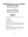
The following topics are covered in this chapter:
Overview
Model Descriptions and Package Checklist
Product Features
Product Hardware Specifications
Product Software Specifications
¾ Applications Development Environment
¾ Networking and Communications Capabilities
¾ Supporting Servers and Daemons
Learning Firmware Build Versions
Memory and File Systems
Hive-Based Registry-Contrast to RAM-Based Registry
Inserting a CompactFlash Card
Inserting a USB Mass Storage
RS-232/422/485 Serial Ports
CAN Ports (IA262 Only)
IA261/262 WinCE User’s Manual
Introduction
Overview
The IA261/IA262 embedded computers, which are ideal for industrial automation applications,
feature 4 RS-232/422/485 serial ports (2 for IA262), dual CAN ports (IA262 only), dual Ethernet
ports, 8 digital input channels, 8 digital output channels, VGA output, 2 USB hosts and a
CompactFlash socket in a compact, industrial-strength aluminum rugged casing. The DIN-Rail
vertical form factor makes the IA261/262 a cost effective solution for installation in small cabinets.
This space-saving solution also facilitates easy wiring, and is the best choice of front-end
embedded controller for industrial applications.
Due to its VGA output capability, IA261/262 is not only play the role of protocol conversion or
data acquisition for the field site devices, it is also suitable for SCADA system in industrial
applications such as manufacturing automation, production line process monitoring, mining
automation etc to be the operator interface terminal at the field site with VGA monitor and proper
HMI software.
The diversified peripherals including RS-232/422/485, CANbus, digital input and digital output
are all designed for industrial environment purpose. To embed the 2KV isolation protection in
these interfaced will make IA261/262 the most reliable solution in industrial harsh environment.
As the dual LAN ports are built, the IA261/262 is an ideal communication platform for Network
Redundant applications.
In addition to the standard model, the IA261/IA262 also comes in wide temperature models. The
IA261-T and IA262-T have an operating temperature range of -40 to 75°C, and are appropriate for
harsh industrial automation environments. The industrial mechanism of the IA261/IA262 design
provides robust, reliable computing. Due to the RISC-based architecture, the IA261/IA262 will not
generate too much heat while being used. The high communication performance and fanless
design make the IA261/IA262 ideal for industrial automation environments.
The IA261/262 embedded computers use a Cirrus Logic EP9315 ARM9, 32-bit, 200 MHz RISC
CPU. Unlike the X86 CPU, which uses a CISC design, the RISC design architecture and modern
semiconductor technology provide the IA261/262 with a powerful computing engine and
communication functions, but without generating a lot of heat. The built-in 32 MB NOR Flash
ROM and 128 MB SDRAM give you enough memory to run your application software directly on
the IA261/262.
IA261/262 comes with the pre-installed Windows CE 6.0, which supports general Windows
and .NET 2.0 environment. It means the program developed by the standard programming tool
like Embedded Visual C++ or Visual Studio 2005 in the Windows PC environment can be
operated without too much porting effort.
1-2
IA261/262 WinCE User’s Manual
Introduction
Model Descriptions and Package Checklist
The IA261/262 Series includes the following models:
IA261-I-CE
RISC-based Embedded Computer with VGA, 4 Serial Ports, Dual LANs, DIO, CompactFlash,
USB, WinCE 6.0, isolation protection for all IO.
IA261-I-T-CE
RISC-based Embedded Computer with VGA, 4 Serial Ports, Dual LANs, DIO, CompactFlash,
USB, WinCE 6.0, Wide Temperature, isolation protection for all IO.
IA262-I-CE
RISC-based Embedded Computer with VGA, 2 Serial Ports, Dual LANs, CAN, DIO,
CompactFlash, USB, WinCE 6.0, isolation protection for all IO.
IA262-I-T-CE
RISC-based Embedded Computer with VGA, 2 Serial Ports, Dual LANs, CAN, DIO,
CompactFlash, USB, WinCE 6.0, Wide Temperature, isolation protection for all IO.
All models of the IA261/262 series are shipped with the following items:
y
1 IA261/262 Embedded Computer
y
Wall-Mounting Kit
y
DIN-Rail Mounting Kit (attach to the product’s casing)
y
Quick Installation Guide
y
Document & Software CD
y
Ethernet Cable: RJ45 to RJ45 cross-over cable, 100 cm
y
CBL-4PINDB9F-100: 4-pin header to DB9 female console port cable, 100 cm
y
Universal Power Adapter
y
Product Warranty Statement
NOTE: Notify your sales representative if any of the above items are missing or damaged.
Product Features
y
Cirrus Logic EP9315 ARM9 CPU, 200 MHz
y
128 MB RAM on-board, 32 MB Flash Disk
y
VGA interface for field site monitoring
y
2KV optically isolated RS-232/422/485 serial ports
y
Dual 10/100 Mbps Ethernet for network redundancy
y
Dual 2KV optically isolated CAN ports with CANopen protocol support
y
8+8 DI/DO with 3KV optical isolation protection
y
12 to 48VDC redundant power input design
y
Support CF socket and USB 2.0 Host
y
Ready-to-Run WinCE 6.0 platform
y
–40 ~ 75°C wide temperature model is available
1-3
IA261/262 WinCE User’s Manual
Introduction
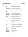
Product Hardware Specifications
System
CPU:
DRAM:
Flash:
Storage Expansion:
USB:
Console/Debugging Port:
Others:
OS:
Display
Graphics Controller:
Cirrus Logic EP9315 ARM9 CPU, 200 MHz
128 MB onboard
32 MB Flash onboard
CompactFlash socket x 1 for storage expansion
USB Host x 2 compliant to USB 2.0 (OHCI), Type A connector
RS-232 x 1 (TxD, RxD, GND), 4-pin header output
RTC, buzzer, Watchdog Timer, Reset button
built-in WinCE 6.0
EP9315 internal graphics accelerator engine with TTL graphical
signal support
Dynamic video memory, share system memory
1024 x 768 (8-bit), 800 x 600 (16-bit), 640 x 480 (24-bit)
CRT interface for VGA output, DB15 female connector
Display memory:
Graphics Resolution:
Display Interface:
Network Communication
Auto-sensing 10/100Mbps x 2, RJ45
LAN:
built-in 1.5KV magnetic isolation protection
Protection:
Serial Communication
IA261: RS-232/422/485 x 4, software-selectable
Serial Port:
IA262: RS-232/422/485 x 2, software-selectable
RS-232 signals: TxD, RxD, DTR, DSR, RTS, CTS, DCD, GND
RS-422 signals: TxD+, TxD-, RxD+, RxD-, GND
4-wire RS-485 signals: TxD+, TxD-, RxD+, RxD-, GND
2-wire RS-485 signals: Data+, Data-, GND
built-in 15KV ESD protection for all signals, 2KV optical isolation
Protection:
protection
5, 6, 7, 8
Data bits:
1, 1.5, 2
Stop bits:
None, Even, Odd, Space, Mark
Parity:
RTS/CTS, XON/XOFF, RS-485 ADDCTM
Flow Control:
50 bps to 921.6 Kbps, supporting non-standard baudrates
Speed:
D-Sub male 9-pin connector
Connector Type:
CAN Communication (IA262 only)
Optically isolated CAN2.0A/2.0B Compliant ports x 2
Interface:
Phillips SJA1000T
CAN Controller:
CAN-H, CAN-L
Signal:
Support CANopen library
Protocol:
2KV optical isolation protection
Protection:
10Kbps to 1Mbps
Speed:
D-Sub male 9-pin connector
Connector Type:
Digital Input
8, source type
Input Channels:
1-4
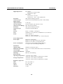
IA261/262 WinCE User’s Manual
Digital input levels:
Protection:
Connector Type:
Digital Output
Output Channels:
On-state Voltage:
Output Current Rating:
Protection:
Connector Type:
LEDs
System:
LAN:
Serial:
Power Requirements
Power Input:
Power Consumption:
Mechanical
Outlook Shape:
Dimensions (WxDxH):
Gross Weight:
Construction Material:
Mounting:
Environmental
Operating Temperature:
Storage Temperature:
Regulatory Approvals
EMC:
Safety:
Others:
Warranty:
Introduction
Dry contact:
Logic level 0: Close to GND
Logic level 1: Open
Wet contact:
Logic level 0: +3V max
Logic level 1: +10V ~+30V (COM to DI)
3KV optical isolation protection
10-Pin Screw Terminal Block (8 points / COM / GND)
8, sink type
24 VDC nominal, open collector to 30 V
Max. 200 mA per channel
3KV optical isolation protection
9-Pin Screw Terminal Block
Power x 1, Ready x 1, Storage x 1
10M/Link x 2 (on connector), 100M/Link x 2 (on connector)
TxD x 4, RxD x 4
IA261: P1 ~ P4 for serial ports
IA262: P1 ~ P2 for serial ports, P3 ~ P4 for CAN ports
Dual power input design
PWR1: 12 to 48 VDC, power jack with thread
PWR2: 12 to 48 VDC, 3-pin terminal block
783 mA @ 12 VDC without loading USB ports,
1.2A @ 12 VDC with loading 2 USB ports
Industrial vertical form factor
60 x 115 x 152 mm (without din-rail kit or wall mount kit)
965 g
Aluminum
DIN-rail, wall mounting
-10 to 60°C (14 to 140°F)
-40 to 75°C (-40 to 167°F) is optional for -T models
-20 to 80°C (-4 to 176°F), 5 to 95% RH
-40 to 85°C (-40 to 185°F) is optional for -T models
FCC, CE (Class A)
UL, cUL, LVD
RoHS, WEEE
5 years
1-5
IA261/262 WinCE User’s Manual
Introduction
Product Software Specifications
IA261/262 WinCE ready-to-run embedded computers are network centric / head-less computers
that are designed to be programmable for embedded communication applications. The following
are the software features of IA26X-CE:
Applications Development Environment
To make IA26X-CE an easy-to-use programming environment, its Windows® CE environment
provides the following common, popular application development features that make
programming convenient and easy as in a PC environment.
y
y
y
y
y
y
y
C Libraries and Run-times - Compared to the C libraries and run-times used on a desktop
PC running Windows®, the C libraries and run-times on a IA26X-CE is a subset of the
WIN32 APIs. It supports full ANSI C run time, standard input/output library, standard
input/output ASCII library and standard ASCII string functions. In addition, it supports
compiler C++ exception handling equivalent and Run-Time Type Information (RTTI)
equivalent to the desktop C++ compilers.
Component Services (COM and DCOM) - The Common Object Model (COM) is an
operating system-independent, object-oriented system for creating binary software
components that can interact with other COM-based components in the same process space, in
other processes, or on remote machines.
Microsoft® Foundation Classes (MFC) - MFC is a comprehensive class library and
complete object-oriented application framework designed to help build applications, COM
components, and controls.
SOAP Toolkit - SOAP is an XML-based protocol for object exchange and remote procedure
calls. Microsoft® Windows® CE 6.0 provides functionality similar to the SOAP Toolkit
version 2 on the desktop. It provides a layer that allows COM objects to use SOAP as the
transport protocol for remote procedure calls and to interact with Web services.
Microsoft® .NET Compact Framework 2.0 with service pack 2 - It offers a choice of
languages, initially Microsoft® Visual Basic® and Microsoft® Visual C#, and eliminates the
common problems faced with language interoperability.
XML- Provides the Document Object Model (DOM) for base XML functionality, support for
XML Query Language (XQL) and XPATH, Extensible Style Sheet Language
Transformations (XSLT) that enables you to transform one class of XML document to another,
SAX2 support for event-based parsing of XML documents and includes MSXML Writer, and
parsing based on Simple API for XML (SAX) for resource-constrained target devices.
Winsock 2.2 - Provides enhanced capabilities over Winsock 1.1, including installable service
providers for additional third-party protocols, as well as Media sense.
Networking and Communications Capabilities
For network centric embedded application usage, IA26X-CE, not only provides powerful
communication hardware interfaces including dual Ethernet and 3-in-I serial ports, but also
supports the networking and communications capabilities that are built-in to Windows® CE 6.0
OS. The features that are well supported are listed as below.
y
y
y
Simple Network Management Protocol (SNMP) - Monitors remote connections to the
network.
Simple Network Time Protocol (SNTP) Client - Provides support for synchronizing the
device’s system time with a SNTP server, and supports Daylight Saving Time.
Serial Communications - In addition to the 16550 UART driver bound to a debug port and
the console port, it includes a special driver for 8 additional Moxa home-made serial ports.
1-6
IA261/262 WinCE User’s Manual
Introduction
y
Network Utilities (IpConfig, Ping, Route) - Utilities for troubleshooting various network
problems.
y
TCP/IP - Includes IP, Address Resolution (ARP), Internet Control Message (ICMP), Internet
Group Membership (IGMP), Transmission Control (TCP), User Datagram (UDP), name
resolution and registration, and DHCP.
Supporting Servers and Daemons
In addition to the development and communication capability, IA26X-CE embeds the services and
daemons as stated next. These common and easy-to-use application servers help users to migrate
the IA26X-CE embedded computer to the industrial communication application very easily and
conveniently.
y
y
y
y
y
y
Telnet Server - A sample server that allows remote administration through a standard telnet
client.
FTP Server - A sample server used for transferring files to and from remote computer
systems over a network using TCP/IP.
File Server - The File Server functionality in Microsoft® Windows® CE enables clients to
access files and other resources over the network.
Web Server (HTTPD) - Includes ASP, ISAPI Secure Socket Layer support, SSL 2, SSL 3,
and Transport Layer Security (TLS/SSL 3.1) public key-based protocols, and Web
Administration ISAPI Extensions.
Dial-up Networking - Consists of RAS client API and the Point to Point Protocol (PPP).
RAS and PPP support Extensible Authentication Protocol (EAP) and RAS scripting.
Watchdog Service – It’s a CPU Hardware function for reset CPU in a user specified time
interval. You must call the Moxa library function to trigger it.
Learning Firmware Build Versions
There are two ways to obtain the firmware version of the IA26X-CE computer. This information is
particularly important for the purpose of feature identification.
y
y
Examine the welcome message after you logon the computer.
Logon the Web-based management system (described in a later chapter) to view the system
information.
Memory and File Systems
From the 128M bytes of SDRAM space, the main memory has a capacity of about 112M bytes in
which the operating system and user applications run. The kernel image occupies the rest of the
space.
The internal file system in the IA26X-CE computer controls access to ROM and also provides file
storage in the object store, which is in the RAM. The ROM file system provides persistent storage
for applications and their related data even when the main power supply is lost. It integrates the
read-only files that are stored in Flash ROM with the read/write files of both an application and a
user. In the IA26X-CE computer, a child directory named “NORFlash” under the root indicates the
ROM storage of the flash memory of size 12M bytes.
The root directory is a RAM file system of size 12M bytes. It can be used for storing temporary
files for your applications. However, do not place persistent files or applications in the root
directory because they will be wiped out when the system is shutdown. Instead, place them under
the directory “NORFlash”.
1-7
IA261/262 WinCE User’s Manual
Introduction
The additional file systems on USB and CompactFlash storage devices are placed at the root of the
internal file system. If you intend to use these devices to port data between your PC and the
IA26X-CE computer, please format them as the FAT file system on your PC.
Hive-Based Registry-Contrast to RAM-Based Registry
The registry for the IA26X-CE is a hive-based registry in contrast to a RAM-based registry. The
hive-based registry stores registry data inside files, or hives, which can be kept on any file system.
This removes the need for performing backup and restore on power off.
Inserting a CompactFlash Card
The IA26X-CE is equipped with a CompactFlash slot of type II which supports cards of both types
- I and II. A mass storage card is considered to be a standard attachment to the computer. Thus,
when an empty mass storage card is inserted into the slot, the computer automatically formats it to
the FAT system. This process takes a few minutes to complete. The IA26X-CE, when a mass
storage card is inserted, creates a directory named “HardDisk” under the root directory and the
newly created directory serves a link to the storage. The IA26X-CE does not support PNP (plug
and play) and hot swap for CompactFlash storage. User must to switch off the power and then
insert Compact Flash storage to slot. And then switch on the power again the IA26X-CE will
detect the CompactFlash storage. If user wants to pull out the Compact Flash storage please
remove the power source first.
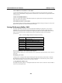
There are some CompactFlash storage disks are not compatible with IA26X-CE. You could try the
other CompactFlash storage or disable ultra DMA using the “System Manager’ to change this
setting.
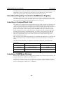
The following table describes the compatible CompactFlash storages list that we had tested
successfully.
Vendor
Device Name
Size
ScanDisk
UltraⅡ
1GB
Transcend
Compact Flash 80X
512MB
Apacer
Photo CIENO
2GB
Unigen
Compact Flash card
128MB
Inserting a USB Mass Storage
When an empty USB storage device is plugged into the USB slot at the back of the IA26X-CE, the
computer automatically formats it to the FAT system.
When the first USB mass storage device is plugged in, a directory named “USBDisk” under the
root directory is created as a link to the storage, on the internal file system. The directory created
for the second plugged in USB device is “USBDisk2”.
1-8
IA261/262 WinCE User’s Manual
Introduction
RS-232/422/485 Serial Ports
The IA261-CE computer comes with 4 high performance serial ports, named “COM1:”, “COM2:”,
“COM3:” and “COM4”.
And the IA262-CE computers has 2 high performance serial ports only named “COM1:” and
“COM2:” all of them are designed to provide reliability, high-speed and 3-in-1 (i.e., RS-232,
RS-422, and RS-485) operation mode switch for your diverse applications. Each of these ports
supports baud rate settings up to 921600 bps.
CAN Ports (IA262 Only)
The IA262-CE computer embedded two CAN ports.
The CAN (Controller Area Network) is a serial communication protocol, which efficiently
supports distributed real-time control with a very high level of security. It is especially suited for
networking “intelligent” devices as well as sensors and actuators within a system or sub-system. In
CAN networks, there is no addressing of subscribers or stations in the conventional sense, but
instead prioritized messages are transmitted. As a stand-alone CAN controller, IA262-CE
represents an economic solution within two independent CAN bus communication ports with a
9-pin D-sub connector. It can be used as master/slave function to cover a wide range of CAN
applications.
1-9
2
Chapter 2
Getting Start
In this chapter, we explain how to operate an IA26X-CE computer via a PC near you. For clarity,
this PC is called a development workstation and the IA26X-CE computer is called a target
computer.
In addition, manual steps are described to facilitate operations such as system time adjustment,
troubleshooting network connectivity, etc. Some of these operations can be done via system
commands after gaining access to the computer and others can be done by a Web-based
management system, which is described in a later chapter.
The following topics are covered in this chapter:
Powering on IA261/262
Resetting Your IA26X-CE Computer
Boot Loader
Operating IA26X-CE Computer Via Serial Console
Changing the Network Settings
¾ Use Windows CE Network Control Panel utility
Operating Your IA26X-CE Computer via Telnet Client
User/Group Management
Adjusting Time Zone
Adjusting System Time
Starting and Stopping Services
Troubleshooting Network Connectivity
Simple Network Management Protocol (SNMP)
¾ SNMP Manager
CANbus Service
IA261/262 WinCE User’s Manual
Getting Start
Powering on IA261/262
Connect the power source located at the top side of the unit to boot up the system. It takes about 5
seconds for the system to boot up and you can hear a clear “BEEP” voice. Once the system is
ready, the “Ready” LED will light up and stay on till you shutdown the computer.
Resetting Your IA26X-CE Computer
Warm-Start: In power-on state, push the “Reset” and release it in 1 second. The computer reboots
itself.
Cold-Start: Switch off and then switch on the power again. The computer reboots itself right
away.
Reset to Factory Defaults (Configuration only): If the computer is not working properly, and
you want to reset it back to factory default settings, press and hold the “Reset” button for 5
seconds in the OS start up state. The buzzer sounds while the factory default settings are loaded.
After the factory default has been loaded, the computer reboots itself. Do not confuse this with the
“Warm-Start”.
Reset to Factory Defaults (Configuration and file system): If the computer cannot be started up.
You must go to the Boot Loader and format the storage flash. After the formatting procedure done,
you should restart it.
Boot Loader
For the OS stability issue, we provide an easy and useful function for you. There are three
important functions in it.
1. Reset to default: you can enforce the WinCE 6.0 to do the “reset to factory” default.
2. Format storage flash: Cause the CE 6.0 file system is the FAT, and we know FAT could be
damaged by unstable power or improper application execution. If the FAT table is crashed you
should not start the OS up. But we can format the file system and reboot IA26X-CE.
At the IA26X-CE startup, it will check the file system and re-partition it if the file system is
empty.
3. Firmware upgrade: If you found a new firmware from Moxa web site, you can upgrade the
firmware by the function. (Details in the appendix A)
Go to the boot loader menu from serial console:
Step1:
Power off IA26X-CE device.
Step2:
Make sure the serial console wire is connect to your PC correctly.
Step3:
Create a new terminal communication from [Start] Æ [Programs] Æ [Accessories] Æ
[Communication] Æ [Terminal] with the setting Baudrate 115200, no hardware flow
control, 8 N 1, character set VT100.
Step4:
Active this terminal window on your PC.
Step5:
Hold “DEL” key continuously.
Step6:
Power on the IA26X-CE device.
2-2
IA261/262 WinCE User’s Manual
Getting Start
Operating IA26X-CE Computer Via Serial Console
The serial console port gives users a convenient way of connecting the development workstation to
the console utility of the target computer. This method is particularly useful when using the
computer for the first time.
After you have wired a serial cable, go back to the development workstation and start a terminal
program (e.g., HyperTerminal) by using the settings shown below for the serial console port.
Baud rate
Parity
Data bits
Stop bits
Flow Control
Terminal
115200bps
None
8
1
None
VT100
After a successful connection, type the login name and password as requested to logon the
computer. The default values are both “admin”.
Login: admin
Password: admin
Changing the Network Settings
The IA26X-CE computer comes with two network interfaces. The default IP addresses and
netmasks of the network interfaces are as follows:
LAN 1
LAN 2
Default IP Address
192.168.3.127
192.168.4.127
Netmask
255.255.255.0
255.255.255.0
Refer to the following to change your network setting.
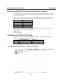
Use Windows CE Network Control Panel utility
1. Move you mouse go to the [Start] Æ [Settings] Æ [Network and Dial-Up Connections].
2-3
IA261/262 WinCE User’s Manual
Getting Start
2. Right-Click the LAN icon and click the [property].
3. Click “OK” button after configuration is done.
Operating Your IA26X-CE Computer via Telnet Client
Before operating your IA26X-CE computer using the Telnet client, we suggest that you change the
network settings of the computer (see the earlier section) to have at least one of the two network
ports situated in the same LAN as your development workstation.
Use a cross-over Ethernet cable to directly connect your development workstation to the target
computer, or a straight-through Ethernet cable to connect the computer to a LAN hub or switch.
Next, use a telnet client in your development workstation to connect to the telnet console utility of
the target computer. Upon a successful connection, type the login name and password as requested
to logon to the computer.
After logging in via the console port or a telnet client, you have a list of busybox commands
available to operate the computer. Use HELP to display all the commands, or type HELP
[command name] to display extended help for the selected command. Some of these commands
such as DATE and TIME are very useful to you to easily manage the system time of the computer.
Others commands such as DIR and MKDIR are good utilities for file management. For example,
to inspect the file structure of the root directory, type DIR
\> dir /b
NORFlash
My Documents
Program Files
Temp
Windows
2-4
IA261/262 WinCE User’s Manual
Getting Start
User/Group Management
User Group: You should assign specific services, such as ftp and telnet, to defined user groups
such that these services are accessible only by the users within the permissible user group. Three
user groups, namely “ftpd”, “telnetd”, and “httpd”, are already created by default for your
convenience.
Adding a Group: Use the command useradd –g <groupName> to create a user group.
\> useradd –g yyyy
group yyyy has been added.
Deleting a Group: To remove a group, use the command userdel –g <groupName>.
\> userdel –g yyyy
group yyyy has been removed.
Adding a User: Use the command useradd <newUserID> to add a user for accessing the system.
The user’s password, by default, is the same as the user name.
\> useradd xxxx
user xxxx has been added.
In addition, you can permit this user to access a particular service by typing -g followed by the
user group name of the service, i.e., useradd –g <groupName> <newUserID>. For example,
\> useradd –g telnetd xxxx
user xxxx is existent
group telnetd is existent
user xxxx has been added to group yyyy
Deleting a User: Use the command userdel <userID> to delete a user from the system. User
“admin” CANNOT be deleted.
\> userdel xxxx
user xxxx has been deleted
You can also just remove a user from a user group by using the command userdel –g
<groupName> <newUserID>. For example,
\> userdel –g yyyy xxxx
user xxxx has been removed from group yyyy
Changing the Password: Please use “System Manager” to change the Password.
2-5
IA261/262 WinCE User’s Manual
Getting Start
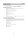
Adjusting Time Zone
Windows CE 6.0 supports Time Zone. You can use [Control Panel]Æ[Date/Time] to adjunct
your current Time Zone. It also supports Daylight Date and Daylight Time.
Adjusting System Time
Setting the System Time Manually: Use the date, and time commands to query the current
system date/time or to set a new system date/time.
\> date
The current date is: Tuesday, November 22, 2005
Enter the new date (mm-dd-[yy]yy): 12-23-05
\> date /T
Wednesday, November 23, 2005
\> time
The current time is: 5:27:17 PM
Enter the new time (hh:mm:ss): 16:02:00
\> time /T
4:02:04 PM
The Date/Time setting would be saved into IA26X-CE RTC. So even the system reboots the date
and time will be still the right time.
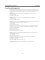
Starting and Stopping Services
After booting up, the IA26X-CE computer runs several services continuously to serve requests
from users or other programs. Notable services include telnet (“TEL0:”), console (“CON0:”),
world wide web HTTP (“HTP0:”), file transfer FTP (“FTP0:”) etc. You seldom need to care about
these services. However, you still can start up or stop a service with its associated name by using
the command “services”. For example,
Start the FTP service by
\> services start FTP0:
Stop the FTP service by
\> services stop FTP0:
The default services in IA26X-CE are listed as below:
TEL0: Telnet Service
FTP0: FTP Service
CON0: Console Service
2-6
IA261/262 WinCE User’s Manual
Getting Start
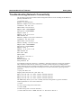
Troubleshooting Network Connectivity
The ipconfig tool prints the TCP/IP-related configuration data of a host including the IP addresses,
gateway and DNS servers.
\> ipconfig /all
Windows IP configuration
Ethernet adapter Local Area Connection:
IP Address: 192.168.4.127
Subnet Mask: 255.255.255.0
Adapter Name: IXP425ETHNPE2
Description: IXP425ETHNPE2
Adapter Index: 2
Address: 80 86 33 33 34 12
DHCP Enabled: NO
Ethernet adapter Local Area Connection:
IP Address: 192.168.14.202
Subnet Mask: 255.255.248.0
Default Gateway: 192.168.15.254
Adapter Name: IXP425ETHNPE1
Description: IXP425ETHNPE1
Adapter Index: 3
Address: 78 56 34 91 cc dd
DHCP Enabled: NO
Host name: IA261
Domain Name:
DNS Servers: 192.168.1.6
NODETYPE: 8
Routing Enabled: NO
Proxy Enabled: NO
To troubleshoot network connectivity, reachability, and name resolution, use the ping command.
This command verifies IP-level connectivity to another TCP/IP computer by sending Internet
Control Message Protocol (ICMP) Echo Request messages. The corresponding return Echo Reply
messages are displayed, along with round-trip times. For more information, type ping without
parameters.
\> ping www.moxa.com
Pinging Host www.moxa.com [192.168.1.16]
Reply from 192.168.1.16: Echo size=32 time<1ms TTL=126
Reply from 192.168.1.16: Echo size=32 time<1ms TTL=126
Reply from 192.168.1.16: Echo size=32 time<1ms TTL=126
The route utility allows you to view or modify network routing tables. Type this command
without parameters to view a list of functions.
\> route
To view current routing items in the tables,
\> route PRINT
To add a routing item on network interface 1,
\> route ADD 192.168.0.0 MASK 255.255.0.0 192.168.15.254 IF 2
2-7
IA261/262 WinCE User’s Manual
Getting Start
To delete a routing item,
\> route DELETE 192.168.0.0
Simple Network Management Protocol (SNMP)
SNMP is the Internet Standard protocol for network management and part of the TCP/IP protocol
suite. SNMP was developed to monitor and manage networks. It uses a distributed architecture
that consists of agents and managers:
SNMP agent
The SNMP agent is an SNMP application that monitors network traffic and responds to queries
from SNMP manager applications. The agent also notifies the manager, by sending a trap, when
significant events occur.
SNMP Manager
An SNMP manager is an SNMP application that generates queries to SNMP-agent applications
and receives traps from SNMP-agent applications.
The IA26X-CE computer installs an SNMP agent to serve as an SNMP device. You should install
the SNMP manager on the workstation computer (for example, a Linux system) that monitors the
network. After installing the nodes, you need to configure the SNMP manager and agent.
To check SNMP agent capabilities in a target IA26X-CE (e.g, network IP at 192.168.3.127)
computer, please logon the workstation computer that, for example, a Linux-based computer, the
SNMP manager resides and type
\> snmpwalk -v 2c -c public 192.168.3.127 system
SNMPv2-MIB::sysDescr.0 Microsoft Windows CE Version 6.0 (Build 1400)
SNMPv2-MIB::sysObjectID.0 SNMPv2-SMI::enterprises.8691.13.7420
SNMPv2-MIB::sysUpTime.0 1282929
SNMPv2-MIB::sysContact.0 Your System Contact Here
SNMPv2-MIB::sysName.0 WindowsCE
You will see a series of messages from the SNMP agent in the IA26X-CE computer. From there,
you can monitor and manage the computer.
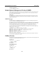
CANbus Service
In IA262-CE we provide some applications to configure CAN Port baud rate and using simple API
to send/receive message thought CANbus service.
Set Baud rate:
canapp <port> <-b> <baud rate >
\>
canapp 1 –b 1000K
Set baudrate !
Set BAUDRATE Done!
Get Baud rate:
canapp <port> <-gb >
\>
canapp 1 –gb
get baudrate !
2-8
IA261/262 WinCE User’s Manual
Getting Start
current baud rate:1000K
Send message:
canapp <port> <-tx > <RTR> <ID> <Message>
\>
canapp 1 –tx 0 123456 88888888
Write msg from port:1
len:8
identifier:123456
Data:38 38 38 38 38 38 38 38
Send Msg Success!
Receive message:
canapp <port> <-rx >
\>
canapp 2 –rx
Read msg from port:2
ReceiveData: 38 38 38 38 38 38 38 38
Set acceptance code:
canapp <port> <-ac > <acceptance code (decimal)> <acceptance mask (decimal)>
\>
canapp 2 –ac 0 4294967295
Set acceptance code !
code=0x0
mask=0xffffffff
IOCTL_CAN_WRITE_ACCEPTANCE_FILTER Done!
2-9
3
Chapter 3
Management Tools
The IA26X-CE series ready-to-run embedded computers are network-centric platforms and are
designed to serve as excellent front-ends for data acquisition and industrial control. Due to the
distributed characteristics of the devices, that these computers control, they often reside in harsh
areas as the devices themselves and are away from system administrators. To manage these
computers, operations such as networking/server configuration, file management, and process
(thread) monitoring/control become a critical area to consider.
To resolve these management issues and accordingly reduce the toil of system administration, a
management system is installed into the IA26X-CE computer.
Before operating the system, please make sure you have a CRT or LCD monitor connection to
your IA26X-CE embedded computer. Then, double-click the desktop icon [System Manager].
The following topics are covered in this chapter:
System Information
Serial Port Configuration
Process (Thread) Monitoring/Control
Services Monitoring/Control
Display
User/Group Management
Auto Launch Configuration
Web Server Configuration
IA261/262 WinCE User’s Manual
Management Tools
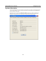
System Information
The first page displays the system information of the IA26X-CE computer, including the firmware
version of the computer, .Net CF version, the system time, and system resources including main
memory and file system usage.
In this page user can click on the “Enable Ultra DMA” check box to enable or disable Ultra
DMA for CF card. If system can not detect some CF cards please disable this setting. If user
changes this setting please reboot system again to make sure the setting take effect.
3-2
IA261/262 WinCE User’s Manual
Management Tools
Serial Port Configuration
The IA261-CE contains 4 and IA262-CE contains 2 high-performance serial ports. When the
system starts up you can specify the default operation mode (RS-232, 422 or 485). The factory
default mode would be RS-232.
Following figure indicates condition of IA261-CE.
Following figure indicates condition of IA262-CE.
3-3
IA261/262 WinCE User’s Manual
Management Tools
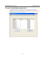
Process (Thread) Monitoring/Control
At runtime, the IA26X-CE computer manages up to 32,000 applications. You can use the
management system to monitor and control them. To view current processes, please click the
Processes item on the tab bar. The running processes are then displayed. You can kill a process by
clicking the “kill” button next to the process name.
3-4
IA261/262 WinCE User’s Manual
Management Tools
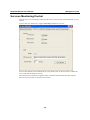
Services Monitoring/Control
Some services run on the background to provide services, such as FTP, Telnet and HTTP, for user
requests.
You can click on a check box to toggle a start/stop operation for a service.
You can also adjust the time automatically by using SNTP. Click on the check box to enable the
service and click the button to activate.
Some listed services cannot be stopped in order to maintain normal operation of the computer.
Such services do not have a check box next to them.
3-5
IA261/262 WinCE User’s Manual
Management Tools
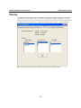
Display
The IA26X-CE VGA output works through DB15 Female CRT connector to display the Windows
CE desktop into a LCD monitor or a CRT monitor. The default setting is “800x600”, 16 bit and
60Hz. For general purpose, you should tune the setting to match your LCD or CRT in specification.
In the Display setting window you can adjust the setting and press “Apply” to save the setting.
Note: You must restart (reboot) your IA26X-CE to make the setting take effect.
3-6
IA261/262 WinCE User’s Manual
Management Tools
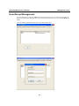
User/Group Management
You can add users by click the “Add” button to assign specific services, such as ftp and telnet, to
define user groups such that these services are accessible and remove users by click the “Remove”
button.
User can change login Password by click expectative name twice.
3-7
IA261/262 WinCE User’s Manual
Management Tools
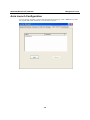
Auto Launch Configuration
You can specify programs to execute automatically after booting up. Click “Add” button to add
the program and restart IA26X-CE to execute these programs.
3-8
IA261/262 WinCE User’s Manual
Management Tools
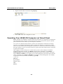
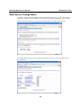
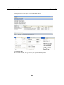
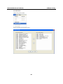
Web Server Configuration
You need a Windows 2000 or Windows XP for Web administration. Try to open a “IE” and go to
URL http://192.168.3.127/WebAdmin (e.g. the IA26X-CE network IP address is 192.168.3.127).
After the logon information you could see the standard Web server Administration page.
In this administration page, you can create a new web site or create a virtual web path for your
web application.
3-9
IA261/262 WinCE User’s Manual
Management Tools
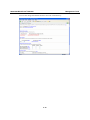
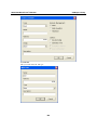
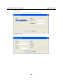
You can also change the authentication for each web virtual directory.
3-10
A
Appendix A
Firmware Upgrade Procedure
To upgrade the IA26X-CE firmware, you must download the firmware upgrade installation file.
This firmware installation file is on the software CD. You can also download the newest version
from the Moxa Download Center. The URL is shown below.
http://web4.moxa.com/support/download_center.asp
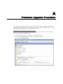
Use the following steps to upgrade the firmware. Before you start, make sure your PC has the
TFTP server software installed correctly.
1. Locate the firmware file (e.g., IA261CE_V1.0_07091112.hfm).
2. Go to the Boot Loader menu first. (Follow the chapter 2 section 4)
Select option (2) TFTP Config.
ThinkCore IA261/262 WinCE User’s Manual
Firmware Upgrade Procedure
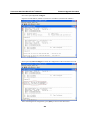
Next select option (2) User Configure
Input the local IP address (IA26X-CE) and server IP address (TFTP host IP Address)
Select option (3) Show Configure to check the configuration of the local IP and server IP.
After confirming the IP configuration, press [ESC] to return to the main menu.
A-2
ThinkCore IA261/262 WinCE User’s Manual
Firmware Upgrade Procedure
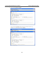
3. Select option (1) Firmware Update.
Select option (1) Load from LAN2, and input the firmware file name (e.g.,
IA262CE_V1.0_0704210.hfm) and press [Enter].
A-3
ThinkCore IA261/262 WinCE User’s Manual
Firmware Upgrade Procedure
A-4
B
Appendix B
CANopen Library
The Moxa IA262-CE comes with dual CAN ports as well as the CANopen protocol library support.
This chapter will guide you on how to use the CANopen library to program CAN communication
applications.
The following topics are covered in this appendix.
CANopen Introduction
Using Dictionary Editor GUI
Function Description
IA261/262 WinCE User’s Manual
CANopen Library
CANopen Introduction
CANopen is a field bus protocol based on the Controller Area Network (CAN). As the name
implies, it is a open network standard accepted throughout the world. While created as a field bus
protocol for industrial automation, CANopen finds use in a wide range of other non-industrial
applications. There are so many possibilities, in fact, that it is possible to write volumes on
specialized uses of the protocol. Rather than being specific to one narrow application or even one
field, we present here a more generalized approach: a generic communication stack based on
CANopen that can be tailored to the user’s needs. This article focuses only on what is covered in
the CAN in Automation (CiA) standard DS-301. In fact, most of the discussion is limited to the
predefined areas of the specification, with emphasis on understanding how the code provided with
this application note functions and how users might develop an application on the CANopen
Stack.
CANopen defines protocols for the following tasks:
•
Configuring a CAN network.
•
Transmitting data to a specific node or in broadcast.
• Administrate the network. For example control the state of the slave node.
The documentation can be found on the CAN automation website:
http://www.can-cia.de/canopen
The most important document about CANopen is the normative CiA Draft Standard 301, version
4.02. You can now download at no cost from the CAN automation website.
Our CANopen Stack provides the lower layers of the protocol. Some of the features of this design
include:
•
Conform to DS301. V.4.02
•
Master and Slave functionality
•
Programmable transfer-rate 10K, 20K, 50K, 125K, 250K, 500K, 800K,1000K
•
Sending SYNC
•
1 SDO server per node
•
Unlimited SDO clients
•
SDO transmission modes: normal, expedited, download, and upload
•
Unlimited PDO receives
•
Unlimited PDO transmits
•
Object Data type: 8, 16, 32 bits values, and fixed length strings
•
Slave state full implemented
•
NMT to change slave’s state
•
PDO transmission mode: on request, every reception of 0 to n SYNC, on event.
•
NMT Heartbeat: A node can be either heartbeat producer or receiver.
•
NMT NodeGuard: Not fully implemented.
The protocol is designed in three levels, as shown in Figure 1. The lowest level is the CANbus
driver providing hardware abstracted CAN support. The communications management level is the
primary interface between the driver and the individual endpoint handling. Besides the application,
there is also the dictionary. In essence, it resides outside of the communication object, and is
directly connected to the SDO endpoint.
B-2
IA261/262 WinCE User’s Manual
CANopen Library
The CANopen specification defines several possible endpoints. The five endpoint objects listed
below are implemented in this protocol; others may be made available in the future.
• The Server SDO
• Four Static PDOs
• Synchronization Consumer
• Network Management Slave
• Node Guard or Heartbeat
SERVER SDO COMMUNICATION
The default server SDO (Service Data Object) is provided. The SDO communications path is
directly linked to the object dictionary; SDO messages contain information that relates the SDO to
a particular object. Data in every message is decoded, validated, and (if valid) eventually executed.
There are essentially two basic operations: read and write. Thus each complete SDO transfer
(which may be multiple messages) will either read or write a single object referenced in the
dictionary.
PDO COMMUNICATION
The PDO (Process Data Object) communications path is linked directly to the applicable
application object or objects. Thus the path is assumed by the device and no path information is
contained within the communication. Essentially the data is mapped internally to one or more
objects. Data is either statically mapped (compiled) or dynamically mapped (set at runtime). One
message can contain data from more than one object.
The protocol provided with this application note supports the four PDOs.
B-3
IA261/262 WinCE User’s Manual
CANopen Library
NETWORK MANAGEMENT CONSUMER
A Network Management (NMT) slave is provided as required by the specification. The NMT
Object receives commands to change the state of the device or reset the device’s application and/or
communications.
NODE GUARD/HEARTBEAT
There is a single Node Guard or Heartbeat endpoint as required by the CANopen specifications.
They both exist in our protocol.
SYNCHRONIZATION CONSUMER
One synchronization consumer (SYNC) is provided. The SYNC message is simply an event to the
application to generate any synchronized PDO messages.
Using Dictionary Editor GUI
The object dictionary functions as a central information database for the device. Every object
within the device is represented within the dictionary by an index, subindex, and some access
information. An object can be as simple as a single byte of data or a more complex data structure.
Table 1 shows the basic areas of the dictionary that are defined by index in the CANopen
specification.
Table 1. Location Ranges Within The Object Dictionary
Index
0001-001F
0020-003F
0040-005F
0060-007F
0080-009F
00A0-0FFF
1000-1FFF
2000-5FFF
6000-9FFF
A000-FFFF
Object
Static Data Type
Complex Data Types
Manufacturer Specific Data Types
Device Profile Static Data Types
Device Profile Complex Data Types
Reserved
Communication Profile Area
Manufacturer Specific Profile Area
Standardized Profile Area
Reserved
The CANopen library comes with the following tool:
Object Dictionary Editor GUI. This tool helps a lot in generating object dictionary source code for
each node.
Developing a new node
Creating a new CANOpen node implies defining the Object Dictionary of this node. To do that,
the developer must provide a C file that contains the definitions of all dictionary entries, and an
index table that helps the stack access some entries directly.
1) Using Dictionary Editor GUI
The Object Dictionary Editor is a WxPython based GUI that is used to create the C files needed to
create a new CANOpen node.
B-4
IA261/262 WinCE User’s Manual
CANopen Library
2) Main view
The top list lets you choose a dictionary section. The bottom left list is the index selected from that
dictionary, and the bottom right list contains edited sub-indexes.
3) Create new node
Edit your node name, ID, and type. Choose your specific inherited profile.
B-5
IA261/262 WinCE User’s Manual
CANopen Library
4) Node info
Edit your node name, ID, and type.
B-6
IA261/262 WinCE User’s Manual
CANopen Library
5) Profile editor
Choose the profile to Edit.
Pick up optional chosen profile entries.
B-7
IA261/262 WinCE User’s Manual
CANopen Library
6) User types
Use User Types to implement value boundaries, and string length.
7) Mapped variable
Add your own specific dictionary entries and associated mapped variables.
B-8
IA261/262 WinCE User’s Manual
CANopen Library
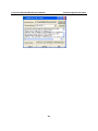
8) Generating the object Dictionary
Once the object dictionary has been edited and saved, you need to generate the object dictionary C
code for your CANopen node. Select the Menu entry “File/Build Dictionary”.
Choose a C file to create or overwrite. The header file will also be created with the same prefix as
the C file.
Function Description
All the functions provided by CANopen library are listed in the following. The detail information
for each function is presented in this section.
1. moxa_getNodeState
Call this function to get node state of slave.
y
Syntax
e_nodeState moxa_getNodeState (CO_Data* d, UNS8 nodeId)
y
Parameters
d: [input] Node handle pointer. This structure contains all necessary information for a CANopen
node.
nodeId: [input] Specified slave’s node ID.
y
Return Values
Return specified state of node.
2. moxa_heartbeatInit
Initial Producer/Consumer Heartbeat time.
y
Syntax
void moxa_heartbeatInit(CO_Data* d)
B-9
IA261/262 WinCE User’s Manual
y
CANopen Library
Parameters
d: [input] Node handle pointer.
y
Return Values
None.
3. moxa_heartbeatStop
Stop Producer/Consumer Heartbeat time.
y
Syntax
void moxa_heartbeatStop(CO_Data* d)
y
Parameters
d: [input] Node handle pointer.
y
Return Values
None.
4. moxa_proceedNODE_GUARD
Use the function to process receiving NMT Node Guarding request from the master.
y
Syntax
void moxa_proceedNODE_GUARD(CO_Data* d, Message* m)
y
Parameters
d: [input] Node handle pointer.
m: [input] CAN message structure.
typedef struct {
SHORT_CAN cob_id; /* l’ID du mesg */
UNS8
rtr;
/* remote transmission request. 0 if not rtr, 1 for a rtr message */
UNS8
len;
/* message length (0 to 8) */
UNS8
data[8];
/* data */
} Message;
y
Return Values
None.
B-10
IA261/262 WinCE User’s Manual
CANopen Library
5. moxa_masterSendNMTstateChange
The function is used to change the state of a slave.
y
Syntax
UNS8 moxa_masterSendNMTstateChange (CO_Data* d, UNS8 Node_ID, UNS8 cs)
y
Parameters
d: [input] Node handle pointer.
ID: [input] Slave device Node-ID (1~127). Set this parameter to 0 to indicate all slave devices.
cs: [input] NMT command specifier.
0x01:
Start
0x02:
Stop
0x80:
PRE-OPERATIONAL
0x81:
Reset_Node
0x82:
Reset_Communication
y
Return Values
1: success, 0: Fail.
6. moxa_masterSendNMTnodeguard
Master sends the Guarding message to slave device.
y
Syntax
UNS8 moxa_masterSendNMTnodeguard(CO_Data* d, UNS8 nodeId)
y
Parameters
d: [input] Node handle pointer.
nodeId: [input] Slave device Node-ID (1~127). Set this parameter to 0 to indicate all slave devices.
y
Return Values
1: success, 0: Fail.
7. moxa_masterRequestNodeState
Use the function to indicate that the master is waiting for a Node_Guard frame from the slave.
B-11
IA261/262 WinCE User’s Manual
y
CANopen Library
Syntax
void moxa_masterRequestNodeState(CO_Data* d, UNS8 nodeId)
y
Parameters
d: [input] Node handle pointer.
nodeId: [input] Slave device Node-ID (1~127). Set this parameter to 0 to indicate all slave devices.
y
Return Values
None.
8. moxa_proceedNMTstateChange
The function is used to change the state of a slave.
y
Syntax
void moxa_proceedNMTstateChange(CO_Data* d, Message * m)
y
Parameters
d: [input] Node handle pointer.
m: [input] CAN message structure.
y
Return Values
None.
9. moxa_slaveSendBootUp
Use the function to send boot up message to master.
y
Syntax
UNS8 moxa_slaveSendBootUp(CO_Data* d)
y
Parameters
d: [input] Node handle pointer.
y
Return Values
1: success, 0: Fail.
10. moxa_getODentry
Read an entry from the object dictionary.
B-12
IA261/262 WinCE User’s Manual
y
CANopen Library
Syntax
UNS32 moxa_getODentry( CO_Data* d,
UNS16 wIndex,
UNS8 bSubindex,
void * pDestData,
UNS8 * pExpectedSize,
UNS8 * pDataType,
UNS8 checkAccess)
y
Parameters
d: [input] Node handle pointer.
wIndex: [input] The index in the object dictionary where you want to read an entry.
bSubindex: [input] The subindex of the Index.
pDestData: [input] Pointer to the variable where the value of this object dictionary entry should be
copied.
pExpectedSize: [input] This function writes the size of the copied value (in Byte) into this
variable.
pDataType: [input] The type of the data.
CheckAccess: [input] if other than 0, do not read if the data is Write Only.[always 0].
y
Return Values
OD_SUCCESSFUL.
SDOABT_TOGGLE_NOT_ALTERNED.
SDOABT_TIMED_OUT.
SDOABT_OUT_OF_MEMORY.
SDOABT_GENERAL_ERROR.
SDOABT_LOCAL_CTRL_ERROR.
11. moxa_setODentry
Use the function to write an entry into the object dictionary.
B-13
IA261/262 WinCE User’s Manual
y
CANopen Library
Syntax
UNS32 moxa_setODentry( CO_Data* d,
UNS16 wIndex,
UNS8 bSubindex,
void * pSourceData,
UNS8 * pExpectedSize,
UNS8 checkAccess)
y
Parameters
d: [input] Node handle pointer.
wIndex: [input] The index in the object dictionary where you want to write an entry.
bSubindex: [input] The subindex of the Index.
pSourceData: [input] Pointer to the variable that holds the value that should be copied into the
object dictionary.
pExpectedSize: [input] The size of the value (in Byte).
checkAccess: [input] if other than 0, do not read if the data is Read Only or Constant.
y
Return Values
OD_SUCCESSFUL
SDOABT_TOGGLE_NOT_ALTERNED
SDOABT_TIMED_OUT
SDOABT_OUT_OF_MEMORY
SDOABT_GENERAL_ERROR
SDOABT_LOCAL_CTRL_ERROR
12. moxa_RegisterSetODentryCallBack
Use the function to register callback function for object dictionary.
y
Syntax
UNS32 moxa_RegisterSetODentryCallBack (CO_Data* d, UNS16 wIndex, UNS8 bSubindex,
ODCallback_t Callback)
B-14
IA261/262 WinCE User’s Manual
y
CANopen Library
Parameters
d: [input] Node handle pointer.
wIndex: [input] The index in the object dictionary where you want to write an entry.
bSubindex: [input] The subindex of the Index.
Callback: [input] assigned callback function.
y
Return Values
NULL if index not found, else: return the table part of the object dictionary.
13. moxa_sendPDO
This function is used to send PDO.
y
Syntax
UNS8 moxa_sendPDO (CO_Data* d, s_PDO pdo, UNS8 request)
y
Parameters
d: [input] Node handle pointer.
pdo: [input] pdo is a structure which contains the data to transmit.
typedef struct struct_s_PDO {
UNS32 cobId;
/* COB-ID */
UNS8
len;
UNS8
data[8]; /* Contain the data */
/* Number of data transmitted (in data[]) */
}s_PDO;
Request: [input] Request can take the value REQUEST or NOT_A_REQUEST.
y
Return Values
0xFF: Can’t send PDO because the state of node is not in operational mode.
1: Success, 0: Fail.
14. moxa_PDOmGR
Prepare a PDO frame transmission.
y
Syntax
UNS8 moxa_PDOmGR (CO_Data* d, UNS32 cobId)
B-15
IA261/262 WinCE User’s Manual
y
CANopen Library
Parameters
d: [input] Node handle pointer.
Cobid: [input] COB-ID.
y
Return Values
The result of the function moxa_sendPDO or 0xFF if error
15. moxa_buildPDO
Prepare the PDO defined at index to be sent by moxa_PDOmGR.
y
Syntax
UNS8 moxa_buildPDO (CO_Data* d, UNS16 index)
y
Parameters
d: [input] Node handle pointer.
Index: [input] The index in the object dictionary.
y
Return Values
0 if success or 0xFF if error
16. moxa_sendPDOrequest
Transmit a PDO request frame to the slave.
y
Syntax
UNS8 moxa_sendPDOrequest (CO_Data* d, UNS32 cobId)
y
Parameters
d: [input] Node handle pointer.
cobId: [input] COB-ID
y
Return Values
0xFF if error, other in success.
17. moxa_proceedPDO
Handle a receiving PDO frame.
y
Syntax
UNS8 moxa_proceedPDO (CO_Data* d, Message *m)
B-16
IA261/262 WinCE User’s Manual
y
CANopen Library
Parameters
d: [input] Node handle pointer.
m: [input] CAN message structure.
y
Return Values
0xFF if error, else return 0
18. moxa_SDOlineToObjdict
Copy the data received from the SDO line transfert to the object dictionary.
y
Syntax
UNS32 moxa_SDOlineToObjdict (CO_Data* d, UNS8 line)
y
Parameters
d: [input] Node handle pointer.
line: [input ]SDO channel.
y
Return Values
SDO error code if error. Else, returns 0
19. moxa_objdictToSDOline
Copy the data from the object dictionary to the SDO line for a network transfer.
y
Syntax
UNS32 moxa_objdictToSDOline (CO_Data* d, UNS8 line)
y
Parameters
d: [input] Node handle pointer.
line: [input] SDO channel.
y
Return Values
SDO error code if error. Else, returns 0
20. moxa_lineToSDO
Copy the data from an existent line.
y
Syntax
UNS8 moxa_lineToSDO (CO_Data* d, UNS8 line, UNS8 nbBytes, UNS8 * data)
B-17
IA261/262 WinCE User’s Manual
y
CANopen Library
Parameters
d: [input] Node handle pointer.
line: [input] SDO channel.
nbBytes: [input] size of data
data: [input] specified data which want to copy to sdo.
y
Return Values
0xFF if error. Else, returns 0
21. moxa_SDOtoLine
Add data to an existent line.
y
Syntax
UNS8 moxa_SDOtoLine (CO_Data* d, UNS8 line, UNS8 nbBytes, UNS8 * data)
y
Parameters
d: [input] Node handle pointer.
line: [input] SDO channel
nbBytes: [input] size of data
data: [input] specified data which want to save to existent line.
y
Return Values
0xFF if error. Else, returns 0
22. moxa_failedSDO
The function will be called when an internal SDO abort occurs.
y
Syntax
UNS8 moxa_failedSDO (CO_Data* d, UNS8 nodeId, UNS8 whoami, UNS16 index, UNS8
subIndex, UNS32 abortCode)
y
Parameters
d: [input] Node handle pointer.
nodeId: [input] specified node id
whoami: [input] SDO_SERVER ,SDO_CLIENT,SDO_UNKNOWN
B-18
IA261/262 WinCE User’s Manual
CANopen Library
index: [input] The index in the object dictionary where you want to handle.
subIndex: [input] The subindex of the Index.
abortCode: [input] SDO abort code
y
Return Values
0xFF if unable to send the SDO abort, else return 0.
23. moxa_resetSDO
Reset all SDO buffers.
y
Syntax
void moxa_resetSDO (CO_Data* d)
y
Parameters
d: [input] Node handle pointer.
y
Return Values
None.
24. moxa_resetSDOline
Reset an unused line.
y
Syntax
void moxa_resetSDOline (CO_Data* d, UNS8 line)
y
Parameters
d: [input] Node handle pointer.
line: [input] SDO channel.
y
Return Values
None.
25. moxa_initSDOline
Initialize some fields of the structure.
y
Syntax
UNS8 moxa_initSDOline (CO_Data* d, UNS8 line, UNS8 nodeId, UNS16 index, UNS8 subIndex,
UNS8 state)
B-19
IA261/262 WinCE User’s Manual
y
CANopen Library
Parameters
d: [input] Node handle pointer.
line: [input] SDO channel.
nodeId: [input]specified node id.
index: [input] The index in the object dictionary where you want to handle.
subIndex: [input]The subindex of the Index.
State: [input]
SDO_RESET
/* Transmission not started. Init state. */
SDO_FINISHED
/* data are available */
SDO_ABORTED_RCV
/* Received an abort message. Data not available */
SDO_ABORTED_INTERNAL
/* Aborted message. */
SDO_DOWNLOAD_IN_PROGRESS
/* downloading */
SDO_UPLOAD_IN_PROGRESS
y
/*uploading */
Return Values
0.
26. moxa_getSDOfreeLine
Search for an unused line.
y
Syntax
UNS8 moxa_getSDOfreeLine (CO_Data* d, UNS8 whoami, UNS8 *line)
y
Parameters
d: [input] Node handle pointer.
whoami: [input] SDO_SERVER or SDO_CLIENT
line: [output] SDO free channel.
y
Return Values
0xFF if all the lines are on use. Else, return 0
27. moxa_getSDOlineOnUse
Search for the line which be used.
B-20
IA261/262 WinCE User’s Manual
y
CANopen Library
Syntax
UNS8 moxa_getSDOlineOnUse (CO_Data* d, UNS8 nodeId, UNS8 whoami, UNS8 *line)
y
Parameters
d: [input] Node handle pointer.
whoami: [input] SDO_SERVER or SDO_CLIENT.
line: [output] on use SDO channel.
y
Return Values
0xFF if error. Else, return 0
28. moxa_closeSDOtransfer
Close a transmission.
y
Syntax
UNS8 moxa_closeSDOtransfer (CO_Data* d, UNS8 nodeId, UNS8 whoami)
y
Parameters
d: [input] Node handle pointer.
nodeId: [input] Node id of the server if both server or client.
whoami: [input] Line opened as SDO_CLIENT or SDO_SERVER.
y
Return Values
0xFF if error. Else, return 0
29. moxa_getSDOlineRestBytes
Bytes in the line structure which must be transmitted (or received).
y
Syntax
UNS8 moxa_getSDOlineRestBytes (CO_Data* d, UNS8 line, UNS8 * nbBytes)
y
Parameters
d: [input] Node handle pointer.
line: [input] SDO channel.
nbBytes: [output] Number of data received or to be sent.
B-21
IA261/262 WinCE User’s Manual
y
CANopen Library
Return Values
0
30. moxa_setSDOlineRestBytes
Store in the line structure the nb of bytes which must be transmitted (or received).
y
Syntax
UNS8 moxa_setSDOlineRestBytes (CO_Data* d, UNS8 line, UNS8 nbBytes)
y
Parameters
d: [input] Node handle pointer.
line: [input] SDO channel.
nbBytes: [input] Number of data received or to be sent.
y
Return Values
Return 0 if success, 0xFF if error
31. moxa_sendSDO
Transmit a SDO frame
y
Syntax
UNS8 moxa_sendSDO (CO_Data* d, UNS8 whoami, s_SDO sdo)
y
Parameters
d: [input] Node handle pointer.
whoami: [input]SDO_CLIENT or SDO_SERVER.
sdo: [input] sdo is a structure which contains the sdo data to transmit.
y
Return Values
0xFF if error, else 0.
32. moxa_sendSDOabort
Transmit a SDO error to the client.
y
Syntax
UNS8 moxa_sendSDOabort (CO_Data* d, UNS8 whoami, UNS16 index, UNS8 subIndex,
UNS32 abortCode)
B-22
IA261/262 WinCE User’s Manual
y
CANopen Library
Parameters
d: [input] Node handle pointer.
Whoami: [input] SDO_CLIENT or SDO_SERVER.
index: [input] The index in the object dictionary where you want to handle.
subIndex: [input] The subindex of the Index.
abortCode:[input] SDO abort code.
y
Return Values
Return 1 if success, 0xFF and 0 if error
33. moxa_proceedSDO
Handle a receiving SDO frame.
y
Syntax
UNS8 moxa_proceedSDO (CO_Data* d, Message *m)
y
Parameters
d: [input] Node handle pointer.
m: [input] CAN message structure.
y
Return Values
Return 0xFF if error,0x80 if transfer aborted by the server ,0x0 is success.
34. moxa_writeNetworkDict
Used by the application to send a SDO request frame and write the data at the index and subIndex
indicated.
y
Syntax
UNS8 moxa_writeNetworkDict (CO_Data* d, UNS8 nodeId, UNS16 index, UNS8 subIndex,
UNS8 count, UNS8 dataType, void *data)
y
Parameters
d: [input] Node handle pointer.
nodeId: [input] nodeId:specified node id
index: [input] The index in the object dictionary where you want to handle.
subIndex: [input] The subindex of the Index.
B-23
IA261/262 WinCE User’s Manual
CANopen Library
count: [input] nb of bytes to write in the dictionary.
dataType: [input] defined in objdictdef.h
data: [input] specified data.
y
Return Values
0xFF if error, else return 0
35. writeNetworkDictCallBack
Used by the application to send a SDO request frame with callback functions and write the data at
the index and subIndex indicated.
y
Syntax
UNS8 moxa_writeNetworkDictCallBack (CO_Data* d, UNS8 nodeId, UNS16 index, UNS8
subIndex, UNS8 count, UNS8 dataType, void *data, SDOCallback_t Callback)
y
Parameters
d: [input] Node handle pointer.
nodeId: [input] nodeId:specified node id
index: [input] The index in the object dictionary where you want to handle.
subIndex: [input] The subindex of the Index.
count: [input] nb of bytes to write in the dictionary.
dataType: [input] defined in objdictdef.h
data: [input] specified data.
Callback: [input]callback function.
y
Return Values
0xFF if error, else return 0
36. moxa_readNetworkDict
Used by the application to send a SDO request frame to read object from the dictionary of a server
node.
y
Syntax
UNS8 moxa_readNetworkDict (CO_Data* d, UNS8 nodeId, UNS16 index, UNS8 subIndex,
UNS8 dataType)
B-24
IA261/262 WinCE User’s Manual
y
CANopen Library
Parameters
d: [input] Node handle pointer.
nodeId: [input] nodeId:specified node id
index: [input] The index in the object dictionary where you want to handle.
subIndex: [input]The subindex of the Index.
dataType: [input] defined in objdictdef.h
y
Return Values
0xFF if error, else return 0.
37. moxa_readNetworkDictCallback
Used to send a SDO request frame to read a object from dictionary.
y
Syntax
UNS8 moxa_readNetworkDictCallback (CO_Data* d, UNS8 nodeId, UNS16 index, UNS8
subIndex,
UNS8 dataType, SDOCallback_t Callback)
y
Parameters
d: [input] Node handle pointer.
nodeId: [input] nodeId:specified node id
index: [input] The index in the object dictionary where you want to handle.
subIndex: [input] The subindex of the Index.
dataType: [input] Defined in objdictdef.h
Callback: [input] The function Callback which must be defined in the user code.
y
Return Values
0xFF if error, else return 0
38. moxa_getReadResultNetworkDict
Use this function after a moxa_readNetworkDict to get the result of the read.
y
Syntax
UNS8 moxa_getReadResultNetworkDict (CO_Data* d, UNS8 nodeId, void* data, UNS8 *size,
UNS32 * abortCode
B-25
IA261/262 WinCE User’s Manual
y
CANopen Library
Parameters
d: [input] Node handle pointer.
nodeId: [input]specified node id
data: [output] specified data pointer.
size: [output] size of data.
abortCode: [output] 0 = not available. Else: SDO abort code.
y
Return Values
SDO_FINISHED
// data is available
SDO_ABORTED_RCV
// Transfert failed. (abort SDO received)
SDO_ABORTED_INTERNAL
// Transfert failed. Internal abort.
SDO_UPLOAD_IN_PROGRESS
// Data not yet available
SDO_DOWNLOAD_IN_PROGRESS // Should not arrive !
39. moxa_getWriteResultNetworkDict
Use this function after a moxa_writeNetworkDict to get the result of the write.
y
Syntax
UNS8 getWriteResultNetworkDict (CO_Data* d, UNS8 nodeId, UNS32 * abortCode)
y
Parameters
d: [input] Node handle pointer.
nodeId: [input]specified node id
abortCode: [output] 0 = not available. Else: SDO abort code
y
Return Values
SDO_FINISHED
// data is available
SDO_ABORTED_RCV
// Transfert failed. (abort SDO received)
SDO_ABORTED_INTERNAL
// Transfert failed. Internal abort.
SDO_DOWNLOAD_IN_PROGRESS // Data not yet available
SDO_UPLOAD_IN_PROGRESS
// Should not arrive !
B-26
IA261/262 WinCE User’s Manual
CANopen Library
40. moxa_getState
Return the state of the node.
y
Syntax
e_nodeState moxa_getState (CO_Data* d)
y
Parameters
d: [input] Node handle pointer.
y
Return Values
Initialisation
= 0x00,
Disconnected
= 0x01,
Connecting
= 0x02,
Preparing
= 0x02,
Stopped
= 0x04,
Operational
= 0x05,
Pre_operational
= 0x7F,
Unknown_state
= 0x0F
41. moxa_setState
Change the state of the node.
y
Syntax
UNS8 moxa_setState (CO_Data* d, e_nodeState newState)
y
Parameters
d: [input] Node handle pointer.
newState: [input]
Initialisation
= 0x00,
Disconnected
= 0x01,
Connecting
= 0x02,
Preparing
= 0x02,
Stopped
= 0x04,
B-27
IA261/262 WinCE User’s Manual
Operational
= 0x05,
Pre_operational
= 0x7F,
Unknown_state
= 0x0F
y
CANopen Library
Return Values
0xFF if error, else return 0.
42. moxa_getNodeId
Return the node Id.
y
Syntax
void moxa_getNodeId (CO_Data* d, UNS8 nodeId)
y
Parameters
d: [input] Node handle pointer.
y
Return Values
Return the node Id.
43. moxa_setNodeId
Define the node ID. Initialize the object dictionary.
y
Syntax
void moxa_setNodeId (CO_Data* d)
y
Parameters
d: [input] Node handle pointer.
y
Return Values
None.
44. moxa_sendSYNC
Transmit a SYNC message.
y
Syntax
UNS8 moxa_sendSYNC (CO_Data* d, UNS32 cob_id)
y
Parameters
d: [input] Node handle pointer.
B-28
IA261/262 WinCE User’s Manual
CANopen Library
cob_id: [input]COB-ID.
y
Return Values
1: success, 0: fail.
45. moxa_proceedSYNC
This function is called when the node is receiving a SYNC message (cob-id = 0x80).
y
Syntax
UNS8 moxa_proceedSYNC (CO_Data* d, Message * m)
y
Parameters
d: [input] Node handle pointer.
m: [input] CAN message structure.
y
Return Values
0 if OK, 0xFF if error.
46. moxa_SetAlarm
Use this to declare a new alarm.
y
Syntax
TIMER_HANDLE moxa_SetAlarm(CO_Data* d, UNS32 id, TimerCallback_t callback,
TIMEVAL value, TIMEVAL period)
y
Parameters
d: [input] Node handle pointer.
id: [input] index of Heartbeat entries.
callback:[input] The callback function.
value: [input] time value
period: [input]Periodicity
y
Return Values
-1 if error, else success.
47. moxa_DelAlarm
Use this to remove an alarm.
B-29
IA261/262 WinCE User’s Manual
y
CANopen Library
Syntax
TIMER_HANDLE moxa_DelAlarm (TIMER_HANDLE handle)
y
Parameters
Handle: [input] timer handle.
y
Return Values
-1.
48. moxa_StartTimerLoop
Use this to start timer loop.
y
Syntax
void moxa_StartTimerLoop (TimerCallback_t init_callback)
y
Parameters
init_callback:[input] the callback function.
y
Return Values
None.
49. moxa_StopTimerLoop
Use this to stop timer loop.
y
Syntax
void moxa_StopTimerLoop (void)
y
Parameters
None.
y
Return Values
None.
50. moxa_canSend
Send CAN message.
y
Syntax
UNS8 moxa_canSend (CAN_PORT port, Message *m)
B-30
IA261/262 WinCE User’s Manual
y
CANopen Library
Parameters
port: [input] specified can port (1 or 2)
m: [input]CAN message structure.
y
Return Values
1: Success, 0: fail.
51. moxa_canReceive
Receive can message.
y
Syntax
UNS8 moxa_canReceive(CAN_PORT fd0, Message *m)
y
Parameters
Fdo:[input] driver data.
typedef struct
{
CO_Data * d;
HANDLE receive_thread;
void* inst;
volatile BOOL continue_receive_thread;
}driver_data;
m:[output] CAN message structure.
y
Return Values
0: success ,else error.
52. moxa_canOpen
The function can initiate the CAN controller and return a handle value for this CAN channel.
y
Syntax
CAN_PORT moxa_canOpen (s_BOARD *board, CO_Data * d)
y
Parameters
board: [input] handle for CAN port.
B-31
IA261/262 WinCE User’s Manual
CANopen Library
struct struct_s_BOARD {
* busname; //port number
* baudrate;//baud rate
};
d: [input] Node handle pointer.
y
Return Values
Return handle value for this CAN port.
53. moxa_canClose
The function can close the CAN controller.
y
Syntax
int moxa_canClose (CO_Data * d)
y
Parameters
d: [input] Node handle pointer.
y
Return Values
0
Example Code
The following example codes can let user to understand how to configure master and slave node.
Both communicate together, performances NMT object and slave’s node provided information to
master through SDO.
Configure Master node:
#include <windows.h>
#include <commctrl.h>
#include <moxa\devices.h>
#pragma comment(lib, “CANopen.lib”)
#pragma comment(lib, “mxdev.lib”)
extern “C”
{
#include <moxa\canopen.h>
B-32
IA261/262 WinCE User’s Manual
CANopen Library
#include “master.h” //this file is generated by Dictionary Editor GUI
}
UNS8 GetChangeStateResults(UNS8 node_id, UNS8 expected_state, unsigned long timeout_ms)
{
unsigned long start_time = 0;
// reset nodes state
win32test_Data.NMTable[node_id] = Unknown_state;
// request slave’s node state, send (identified=700+nodId,rtr=1) to slave.
moxa_masterRequestNodeState(&master_Data, node_id);
start_time = GetTickCount();
while(GetTickCount() - start_time < timeout_ms)
{
if(moxa_getNodeState(&master_Data, node_id) == expected_state)
{
break;
return 0;
}
}
return 0xFF;
}
UNS8 ReadSDO(UNS8 nodeId, UNS16 index, UNS8 subIndex, UNS8 dataType, void* data,
UNS8* size)
{
UNS32 abortCode = 0;
B-33
IA261/262 WinCE User’s Manual
CANopen Library
UNS8 res = SDO_UPLOAD_IN_PROGRESS;
// Read SDO
UNS8 err = moxa_readNetworkDict (&win32test_Data, nodeId, index, subIndex, dataType);
if (err)
return 0xFF;
for(;;)
{
res = moxa_getReadResultNetworkDict (&win32test_Data, nodeId, data, size,
&abortCode);
if (res != SDO_UPLOAD_IN_PROGRESS)
break;
Sleep(1);
continue;
}
moxa_closeSDOtransfer(&win32test_Data, nodeId, SDO_CLIENT);
if (res == SDO_FINISHED)
return 0;
return 0xFF;
}
int _tmain(int argc, _TCHAR* argv[])
{
UNS8 node_id = 0,loop=0;
//indicate canbus port and baudrate.
s_BOARD MasterBoard = {“1”, “1000K”};
int i=0;
B-34
IA261/262 WinCE User’s Manual
CANopen Library
/* process command line arguments */
if (argc < 3)
{
wprintf( TEXT(“USAGE: master <slave’s node_id> \n”) );
return 1;
}
node_id = _wtoi(argv[1]);
if (node_id < 2 || node_id > 127)
{
wprintf(TEXT(“ERROR: node_id shoule be >=2 and <= 127\n”));
return 1;
}
if (moxa_canOpen(&MasterBoard,&master_Data))
{
/* Defining the master node Id */
moxa_setNodeId(&master_Data, 0x01);
/* set the master in operational mode */
moxa_setState(&master_Data, Operational);
/* Ask all slave node to go in operational mode */
moxa_masterSendNMTstateChange (&master_Data, 0, NMT_Start_Node);
B-35
IA261/262 WinCE User’s Manual
CANopen Library
/* wait until slave’s mode will switch to operational state*/
/* if return 0, mean this node entry operational state */
if (GetChangeStateResults(node_id, Operational, 20000) != 0xFF)
{
/*modify Client SDO 1 Parameter, mapping to dictionary
index:1280 ,client:0x600,server:0x580 */
UNS32 COB_ID_Client_to_Server_Transmit_SDO = 0x600 + node_id;
UNS32 COB_ID_Server_to_Client_Receive_SDO = 0x580 + node_id;
UNS32 Node_ID_of_the_SDO_Server = node_id;
UNS8 ExpectedSize = sizeof (UNS32);
if (OD_SUCCESSFUL == moxa_setODentry(&master_Data, 0x1280, 1,
&COB_ID_Client_to_Server_Transmit_SDO, &ExpectedSize, RW)
&& OD_SUCCESSFUL == moxa_setODentry(&maste _Data, 0x1280, 2,
&COB_ID_Server_to_Client_Receive_SDO, &ExpectedSize, RW)
&& OD_SUCCESSFUL == moxa_setODentry(&master_Data, 0x1280, 3,
&Node_ID_of_the_SDO_Server, &ExpectedSize, RW))
{
UNS32 dev_type = 0;
char device_name[64]=““;
char hw_ver[64]=““;
char sw_ver[64]=““;
UNS32 vendor_id = 0;
UNS32 prod_code = 0;
UNS32 ser_num = 0;
UNS8 size;
UNS8 res;
//get information from slave node.
size = sizeof (dev_type);
B-36
IA261/262 WinCE User’s Manual
CANopen Library
res = ReadSDO(node_id, 0x1000, 0, uint32, &dev_type, &size);
printf(“device type: %d\n”,dev_type & 0xFFFF);
size = sizeof (device_name);
res = ReadSDO(node_id, 0x1008, 0, visible_string, device_name, &size);
printf(“device name: %s\n”,device_name);
size = sizeof (hw_ver);
res = ReadSDO(node_id, 0x1009, 0, visible_string, hw_ver, &size);
printf(“HW version: %s\n”,hw_ver);
size = sizeof (sw_ver);
res = ReadSDO(node_id, 0x100A, 0, visible_string, sw_ver, &size);
printf(“SW version: %s\n”,sw_ver);
size = sizeof (vendor_id);
res = ReadSDO(node_id, 0x1018, 1, uint32, &vendor_id, &size);
printf(“vendor id: %d\n”,vendor_id);
size = sizeof (prod_code);
res = ReadSDO(node_id, 0x1018, 2, uint32, &prod_code, &size);
printf(“product code: %d\n”,prod_code);
size = sizeof (ser_num);
res = ReadSDO(node_id, 0x1018, 4, uint32, &ser_num, &size);
printf(“serial number: %d\n”,ser_num);
B-37
IA261/262 WinCE User’s Manual
CANopen Library
}
else
{
wprintf(TEXT(“ERROR: Object dictionary access failed\n”));
}
}
else
{
wprintf(TEXT(“ERROR: node_id %d is not responding\n”),node_id);
}
moxa_masterSendNMTstateChange (&master_Data, 0, NMT_Stop_Node);
moxa_setState(&master_Data, Stopped);
moxa_canClose(&master_Data);
}
return 0;
}
Configure Slave node:
#include <windows.h>
#include <commctrl.h>
#pragma comment(lib, “CANopen.lib”)
extern “C”
{
#include <moxa\canopen.h>
#include “Slave.h”//this file is generated by Dictionary Editor GUI
}
#include <moxa/devices.h>
B-38
IA261/262 WinCE User’s Manual
CANopen Library
int _tmain(int argc, _TCHAR* argv[])
{
//set canbus port and baud rate
s_BOARD MasterBoard = {“2”, “1000K”};
//create canopen
if (moxa_canOpen(&MasterBoard,&Slave_Data))
{
//set slave state to pre-operational
moxa_setState(&Slave_Data, Pre_operational);
//modify Client SDO 1 Parameter, mapping to dictionary, the default node id is 0x05.
UNS32 COB_ID_Client_to_Server_Transmit_SDO = 0x605;
UNS32 COB_ID_Server_to_Client_Receive_SDO = 0x585;
UNS8 ExpectedSize = sizeof (UNS32);
moxa_setODentry(&Slave_Data, 0x1200, 1, &COB_ID_Client_to_Server_Transmit_SDO,
&ExpectedSize, RW);
moxa_setODentry(&Slave_Data, 0x1200, 2, &COB_ID_Server_to_Client_Receive_SDO,
&ExpectedSize, RW) ;
while(1);//wait for master’s command
}
return 0;
}
B-39