1
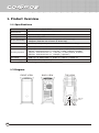
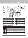
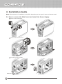
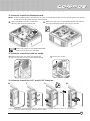
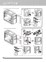
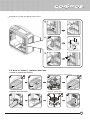
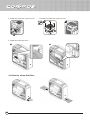
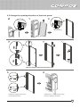
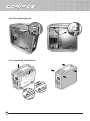
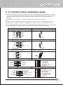
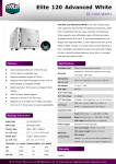
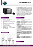
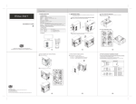
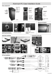
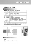
Ver 2.0: 2007/06
CONTENTS
1. Product Overview ............................................................................................ 02
1.1 Specifications .................................................................................................... 02
1.2 Diagram.............................................................................................................. 02
1.3 Part List .............................................................................................................. 03
1.4 Accessory Carrying Case ............................................................................ 03
2. Installation Guide ............................................................................................ 04
2.1 How to remove the Side Panel and install the Power Supply ........................ 04
2.2 How to install the Motherboard ......................................................................... 05
2.3 How to install the add-on cards ........................................................................ 05
2.4 How to install the 3.5” and 5.25” Devices ....................................................... 05
2.5 How to install / replace case fans .................................................................... 07
2.6 How to clean the filter ....................................................................................... 08
2.7 Change the opening direction of the front panel ............................................ 09
2.8 Cable Management ............................................................................................ 10
2.9 Completing Installation ...................................................................................... 10
3. I/O Function Panel Installation Guide .............................................. 11
Icon Description
A tool for assembling is needed
01
1. Product Overview
1.1 Specifications
Available Color
Chassis:Silver , Bezel:Black
Dimensions
(W)266mm x (H)598mm x (D)628mm
Material
Chassis:STEEL
M/B Type
Extended ATX, ATX
Appearance:AL
5.25" Drive Bay
5 Exposed (without the use of exposed 3.5" Drive bay)
4 Expose (with the use of one 3.5" Drive bay)
3.5" Drive Bay
6 Hidden; 1 Exposed (converted from one 5.25" Drive Bay)
Expansion Slot
7
Cooling System
Bottom fan: 120x120x25 mm x 1, 1200 rpm, 17 dBA (intake, included)
Top fan: 120x120x25 mm x 2, 1200 rpm, 17 dBA (exhaust, included)
Rear fan: 120x120x25 mm x 1 , 1200 rpm, 17 dBA (exhaust, included)
HDD fan: 120x120x25 mm x 1, 1200rpm, ( Optional )
I/O Panel
USB 2.0 x 4, IEEE 1394 x 1, Audio x 1, SPK x 1, eSATA x 1
Power Supply
PS2 / EPS 12V ( Optional )
Product specifications are subject to change without notice。
1.2 Diagram
FRONT-VIEW
BACK-VIEW
TOP-VIEW
HEADSET
USB2.0
IEEE1394
E-SATA
RESET
02
MIC
POWER
1.3 Part List
1
16
17
2
Exclusive Giveaway
3
CM Accessory Box
4
5
15
14
6
13
7
Item
1
2
3
4
5
6
7
8
9
8
11
9 10
Parts Name
Top Cover
Rear Fan 120x25mm
Top Fan 120x25mm
Filter (Rear)
VGA Air Duct
Left Side Panel
Shutter Fan Cover
Bottom Fan 120x25mm
Fan Holder
Q'ty
1
1
2
1
1
1
1
1
1
Item
10
11
12
13
14
15
16
17
12
Parts Name
HDD Tray
Filter (Front)
5.25'' Shield
Front Door
FDD-Bracket
Right Side Panel
CM Accessory Box
Casing
Q'ty
6
1
5
1
2
1
1
1
1.4 Accessory Carrying Case
Figure
Parts Name
Q'ty
Screw Driver (Keyring)
Cable Tie
20
HDD-Screw
24
Stand-off (16.9mm)
Stand-off (6.5mm)
#6-32
M3
Extended Cable
Tie Mount
1
3
17
40
30
1
8
Used for
For system install
Cable Management
For HDD
M/B Tray (for Extend ATX M/B)
M/B Tray
MB Tray, Power
CD-ROM,FDD,3.5'' Bracket
For Power Cable 8 pin
Power cable management
03
2. Installation Guide
Note: The sequence of installation may differ depending on the type of case and devices used.
2.1 How to remove the Side Panel and install the Power Supply.
1 Remove the Side Panel
2 Remove the VGA Air Duct
3 Install the Power Supply
#6-32
Inlet for PSU
04
2.2 How to install the Motherboard.
Note: If the I/O plate of the case does not fit your motherboard,please remove the I/O plate and replace
it with the one provided with the motherboard.
1 Align the stand-off holes of M/B with
MB tray and screw the stand-offs.
2 Make sure the holes on the Motherboard and chassis
line up completely before securing the screws.
#6-32
Stand-off (16.9mm) for Extend ATX M/B
Stand-off (6.5mm) for ATX M/B
2.3 How to install the add-on cards.
1 Remove the back slot plate and install the
2 Secure the screw
add-on card into the slot on the Motherboard
2.4 How to install the 3.5” and 5.25” Devices.
1
2
3
M3
4
th
Notice: We strongly recommend installing a device that is no bigger then 3.5" in the 5 device bay to
guarantee optimal thermal performance for HDDs.
05
* Insert the device into 5.25” drive bay
1
2
Unlock
Lock
* FDD/Card Reader Installation
1
M3*5
2
3
4
Unlock
Lock
06
5
* Installation of IDE and SATA Hard Drives
1
2
3
2.5 How to install / replace case Fans
* Install or replace the top fans
Supports two 120mm or 140mm Fans
1
2
* Replace the bottom fan
1
3
4
Supports 120mm Fan
2
3
4
07
* Install the rear fan (Optional item)
* Install the HDD fan (Optional item)
1
2
* Install the VGA Air Duct
1
2.6 How to clean the filter
08
2
2.7 Change the opening direction of the front panel
1
3
2
Press Down
Push up to
remove hinge.
Lift up and out
4
5
6
Remove hinges and insert into other side
7
8
Switch the magnet and screw
to the opposite side.
Replace door - it should now open
from the opposite direction.
09
2.8 Cable Management
SATA
SATA
Power Wire
Power Wire
2.9 Completing Installation
10
3. I/O Function Panel Installation Guide
Please refer to the illustration in the section of USB2.0, IEEE 1394a, eSATA and Audio connector
from the motherboard user manual. Please select the motherboard which uses the same USB2.0,
IEEE1394, eSATA, AC’97,HD Audio standard as below; otherwise, it will cause damages to
device(s).
The following illustration is a connection diagram for the front panel I/O cable.
NEVER connect an IEEE1394 cable to the USB2.0 connector. Doing so will damage the device.
NEVER connect a USB2.0 cable to the IEEE1394 connector. Doing so will damage the device.
On some motherboards, the connectors for IEEE1394, eSATA, USB2.0 and Audio are not the same
as the drawing below. Please check with your motherboard manual before installing.
Motherboard
Front panel IEEE 1394 connector
Cable
IEEE 1394 connector
TPAGND
TPB+12V
GND
TPA+
GND
TPB+
+12V
Pin
No Pin
Front panel USB connector
USB+5V
LPLP+
GND
USB connector
USB+5V
LPLP+
GND
NC
Pin
No Pin
Front panel eSATA connector
GND
TXP
TXN
GND
RXN
RXP
GND
Pin
AC'97
MIC
MIC~BIAS
FPOUT-R
+5V
FPOUT-L
AC'97 Connector
Yellow-MIC
Red-MIC~BIAS
Black-AUD GND
Green-RET~R
Green/Green-FPOUT~R
Blue-RET~L
Blue/Blue-FPOUT~L
GND
AUD GND
RET~R
NO PIN
RET-L
Azalia (Intel High Definition Audio)
PORT1L
PORT1R
PORT2R
SENSE_SEND
PORT2L
eSATA connector
AUD GND
PRESENCE#
SENSE1_RETURN
NO PIN
SENSE2_RETURN
HD Connector
Yellow-PORT1L
Red-PORT1R
Brown-SENSE1_RETURN
Black-AUD GND
White-PRESENCE#
Orange-SENSE_SEND
Gray-SENSE2_RETURN
Green-PORT2R
Blue-PORT2R
11
510002641-GP