1
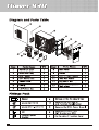
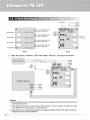
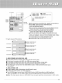
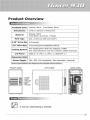
ITower 930
I/O Function Panel Installation Guide
Please refer to the illustration on the
section of USB2.0, IEEE 1394a, and Audio
connector from the motherboard user
manual. Please select the motherboard
which used the same USB2.0, IEEE1394,
AC’97 as below; otherwise, it will cause
damages to device(s).
The following illustration is a connection
diagram for the front panel I/O cable.
NEVER connect an IEEE1394 cable to the
USB2.0 connector. Doing so will damage
the device.
NEVER connect a USB2.0 cable to the
IEEE1394 connector. Doing so will
damage the device.
On some motherboards, the connectors
for IEEE1394, USB2.0 and Audio are not
the same as the drawing below. Please
check with your motherboard manual
before installing.
Motherboard
Cable
Front panel IEEE 1394 connector IEEE 1394 connector
TPA+
GND
TPB+
+12V
No Pin
TPAGND
TPB+12V
GND
Pin
Front panel USB connector
USB+5V
LPLP+
GND
USB connector
USB+5V
LPLP+
GND
NC
No Pin
Pin
AC'97
MIC
MIC-BIAS
FP-OUT-R
AUD-5V
FP-OUT-L
IEEE 1394
USB 2.0
USB2.0
AC'97
AUD-GND
AUD-GND
FP-RETURN-R
KEY
FP-RETURN-L
Intrusion Switch
On the front of the case, you can find some LEDs and switch leads (Power LED,
Message LED, H.D.D LED, Power SW, Reset SW)
Please consult user manual of your motherboard manufacturer, then connect these
leads to the panel header on the motherboard.
These leads are usually labeled; if not, please trace them back to the case front to
find out their source.
-POWER LED
-POWER SW
-H.D.D LED
-RESET SW
-Message LED
18
connects
connects
connects
connects
connects
to
to
to
to
to
your M/B at the PLED.
the PWR connector on the motherboard.
the 2-pin labeled HDD LED connector.
the RSW connector on the motherboard.
your M/B to receive the signal from CPU.