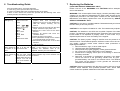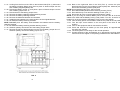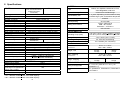
1
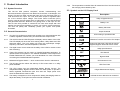
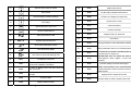
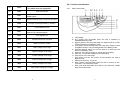
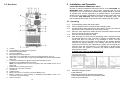
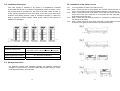
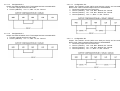
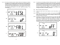
ED6000T & ED6200T
Parallel Redundant
ON-LINE SERIES
User’s Manual
Para Systems, Inc.
1455 LeMay Drive
Carrollton, TX 75007
Phone: 1-972-446-7363
Fax: 1-972-446-9011
Internet: minutemanups.com
UPS Sizing: sizemyups.com
PN – 34000355 R2
Table of Contents
1 Important Safety Instructions................................................... 2
1.1 An Important Notice............................................................... 2
1.2 Life Support Policy ................................................................ 3
1.3 FCC Notice............................................................................ 3
2 Product Introduction ................................................................. 4
2.1 System Overview................................................................... 4
2.2 General Characteristics......................................................... 4
2.3 Symbols on the LCD Display Panel ...................................... 5
2.4 Controls and Indicators ......................................................... 9
2.5 Rear Panels........................................................................... 10
3 Installation and Operation ........................................................ 11
3.1 Unpacking ............................................................................. 11
3.2 Installation Placement ........................................................... 12
3.3 Storage instruction ................................................................ 12
3.4 Installation of the Castor Covers ........................................... 13
3.5 Wiring the Input and Output Connections ............................. 14
3.6 Operation and Setup Instructions.......................................... 19
4 Communication Port, EPO Port and Option Cards ................ 30
4.1 RS232 Communication Port .................................................. 30
4.2 EPO Port ............................................................................... 30
4.3 Option Cards ......................................................................... 31
5 Power Monitoring Software ...................................................... 31
5.1 Hardware Installation............................................................. 31
5.2 Software Installation .............................................................. 31
6 Troubleshooting Guide ............................................................. 32
7 Replacing the Batteries............................................................. 33
7.1 Battery Replacement Procedure ........................................... 34
8 Specifications ............................................................................ 38
9 Obtaining Service ...................................................................... 40
10 Limited Product Warranty....................................................... 41
11 Declaration of Conformity....................................................... 42
© Copyright 2008
1
1 Important Safety Instruction
1.1. An Important Notice
1.1.1
To ensure safety in all applications where a UPS system is hardwired to the
electrical supply the UPS must be installed by a Qualified Electrical
Contractor.
1.1.2
The UPS has its own internal energy source (battery). If the UPS is
switched on when there is no AC power is available, there could be voltage
at the output terminals.
1.1.3
Servicing of the UPS system must be performed by Qualified Service
Personnel ONLY. MINUTEMAN accepts no liabilities and is not limited to:
injury to the Service Personnel, or damages to; the UPS system, or the
connected equipment caused by the incorrect installation or servicing of the
UPS system.
1.1.4
Make sure that the input voltage rating of the UPS matches the supply
voltage.
1.1.5
This UPS series is intended to be install in a temperature controlled
environment that is free of conductive contaminants. Select a location that
will provide good air circulation for the UPS at all times. Avoid locations near
heating devices, water or excessive humidity, or where the UPS is exposed
to direct sunlight. Route power cords so they cannot be walked on or
damaged.
1.1.6
To eliminate overheating of the UPS, keep all ventilation openings free from
obstruction, and do not store anything on top of the UPS system. Keep the
UPS system at least 12” (30 cm) away from the wall.
1.1.7
The battery will discharge naturally if the UPS is unused for any length of
time. The batteries should be recharged every 2-3 months if unused.
1.1.8
This UPS supports electronic equipment in offices, telecommunications,
process control, and medical applications.
1.1.9
Risk of Electrical Shock. Make sure the UPS is completely turned off when
moving the UPS from one location to another.
1.1.10 The UPS has a Maintenance Bypass Switch. Follow the procedures to
perform the maintenance bypass operation.
2
1.1.11 SAVE THESE INSTRUCTIONS - This manual contains important
instructions that should be followed during the Installation and the
Maintenance of the UPS and batteries.
1.1.12 CAUTION - A disconnect switch must be provided by the user for the AC
output circuit when the UPS’s output is hardwired. To reduce the risk of fire,
connect only to a circuit provided with branch circuit over-current protection
(30 amperes for 208/240V output or 50 amperes for single 120V output) in
accordance with the National Electric Code, ANSI/NFPA 70.
1.1.13 CAUTION - To reduce the risk of fire, connect the input to a circuit provided
with branch circuit over-current protection for 40 amperes in accordance
with the National Electric Code, ANSI/NFPA 70. Use No. 8 AWG, 60°C
copper wire and 22.1lb-in Torque force when connecting to terminal block.
1.1.14 CAUTION - To reduce the risk of electrical shock with the installation of this
UPS system and the connected equipment, the installer must ensure that
the combined sum of the AC leakage current does not exceed 3.5mA.
1.1.15 WARNING - This Uninterruptible Power Supply (UPS) contains potentially
hazardous voltages. Do not attempt to disassemble the UPS system
beyond the battery replacement procedure. This UPS system contains no
user serviceable parts. QUALIFIED SERVICE PERSONNEL ONLY must
perform the maintenance and the battery replacement for this UPS system.
1.2. Life Support Policy
As a general policy, we do not recommend the use of any of our products in
life support applications where failure or malfunction of the product can be
reasonably expected to cause failure of the life support device or to
significantly affect its safety or effectiveness. We do not recommend the use
of any of our products in direct patient care. We will not knowingly sell our
products for use in such applications unless it receives in writing assurances
satisfactory to us that (a) the risks of injury or damage have been minimized,
(b) the customer assumes all such risks, and (c) our liability is adequately
protected under the circumstances.
1.3. FCC Notice
This equipment has been tested and found to comply with the limits for a
Class A computing device in accordance with the specifications in Subpart J
of Part 15 of FCC Rules and the Class A limits for radio noise emissions from
digital apparatus set out in the Radio Interference of the Canadian
Department of Communications.
3
2 Product Introduction
2.1. System Overview
This On-Line UPS protects computers, servers, internetworking, and
telecommunications equipment from blackouts, brownouts, overvoltages, and
surges. This On-Line UPS converts the input AC to DC and then back to a
True Sine Wave AC output. The True Sine Wave output is regulated within
2% of the nominal output voltage. The Power Factor Correction (PFC)
circuitry corrects the input power factor to within 98% of unity and blocks the
load generated harmonic distortion from getting back on the input AC line.
This On-Line UPS provides a continuous true sine wave output with zero
transfer time and great regulation to protect your mission critical equipment.
The UPS will quietly and confidently protect your system from power
anomalies.
2.2.9
The temperature-controlled fans will extend the life of the fans and reduce
the annoying noise caused by fans.
2.3. Symbols on the LCD Display Panel
Item
Symbol
Description
1
LINE
Utility or Bypass Source
2
Battery Low
3
Battery Abnormal
4
Output Overload
2.2. General Characteristics
2.2.1
True On-Line architecture continuously supplies your critical equipment with
a stable, regulated, transient-free, pure sine wave AC Output Power.
5
UPS working in specified mode
2.2.2
The multi-functional LCD/LED panel will display various states of the UPS.
The LED display will show the UPS working status, Utility Status and UPS
Abnormal status. The LCD display will show the Input/Output voltage,
frequency, load status, internal temperature, and faults.
6
A Blackout Transfer occurred in UPS Output
2.2.3
The digital control circuit enhances the ability of the UPS for remote control
and monitoring.
2.2.4
These UPS systems can be used in a Parallel Redundant application. To
operate these UPS systems in the Parallel Redundant mode requires the
Parallel Redundant kit. Contact your local distributor for more information
concerning the Parallel Redundant operation.
8
Utility Input Abnormal
9
OFF
UPS Shutoff
10
BPS
Bypass Mode
2.2.5
Maintenance Bypass Switch — which reduces down time for maintenance.
11
2.2.6
The DC-start function allows the start-up of UPS when there is no utility
power available.
12
2.2.7
This UPS system has the Independent Battery Bypass function. The
Independent Battery Bypass function allows the UPS system to provide a
stable, regulated, transient-free pure sine wave AC output power even
when the batteries are weak or dead.
13
2.2.8
The battery management circuit analyses the battery discharging status to
adjust the battery cut-off point and extend the life of batteries.
4
Bypass Input Abnormal, UPS fails to transfer
to Bypass, Bypass Abnormal at ECO mode
7
LINE
OFF
UPS Abnormal Lock
UPS Flow Chart
4 Digits Measurement Display
14
Indicate the item desired to be measured
5
15
ON and Alarm Silencer Switch
32
Er06
Output Short Circuit
16
OFF Switch
33
Er08
DC Bus high-voltage-level abnormal
17
Previous Page or Setting Change
34
Er09
DC Bus low-voltage-level abnormal
18
Next Page
35
Er10
Inverter Over-current
19
Special Function Log in /out
36
Er11
UPS Overheated
20
Enter or Reconfirmed
37
Er12
Inverter Overload
Utility Input Normal LED
38
Er13
Charger Failure or Abnormal
21
39
Er14
Fan Failure
22
Bypass Input Normal LED
40
Er15
Wrong procedure to enter Maintenance Mode
23
UPS under Redundancy Mode
41
Er16
Output parameters Set error in Parallel System
24
UPS under ECO Mode
42
Er17
ID numbers are in conflict in Parallel System or
ID number error in single unit
43
Er18
EEPROM data error. Its values are reset to
default (Normal / 220V / adj0% / +/-3Hz / low
sensitivity)
UPS Fault or Abnormal Warning LED
25
26
EPO
Emergency Power Off
27
Er01
DC BUS capacitor pre-charge abnormal after
50-seconds or Battery Fuse failure
44
Er20
DC Bus voltage cannot be discharged
28
Er02
AC SCR or Battery SCR soft Start abnormal
after 2-seconds
45
Er21
29
Er03
PFC (Boost) soft start abnormal after 30seconds
Parallel communication error (communication
wire disconnected or failure to find ID1 UPS) in
parallel system
46
Er22
Bypass SCR or Output Fuse Fails
30
Er04
Inverter Failure
47
Er23
Inverter Relay or SCR or Output Fuse Fails
31
Er05
Battery Weak or Dead
6
7
2.4. Controls and Indicators
48
Er24
Bypass Input found when running on CVCF
mode (CVCF mode not supported)
49
Er26
PFC Over-current
50
Er27
The UPS must be operated in normal mode in
parallel system
51
Er28
Bypass Overload Time out and cut off output.
52
Er29
Charger overcharges battery (>300Vdc)
53
Er30
Inverter Balance error
54
Er31
The settings of both control board and driver
board are not matched together
55
Er32
Sync Signal error
56
Er33
Isolated transformer overheat
57
Er34
Balance function conflict
58
CEr1
Utility voltage out of range
59
CEr2
Bypass Voltage out of range
60
CEr3
Inverter Voltage out of range
61
CEr4
Load Percentage out of range
62
CEr5
Battery Voltage out of range
2.4.1
UPS Control panel
A
B
C
D
E
F
G
H
I
J
K
L
63
CEr6
UPS Output Voltage out of range
LCD Display.
N+1 (green) LED illuminates when the UPS is operating in the
Parallel/Redundant mode.
Bypass (green) LED illuminates when the bypass input is normal. The
LED extinguishes in the Battery mode.
Line (green) LED illuminates when the utility input voltage is within the
acceptable window. The LED extinguishes in the Battery mode.
On/Alarm Silencer switch is to turn the UPS On or silence the audible
alarm in the Battery mode.
Up arrow: Go to previous page or change the UPS setting.
Enter key: To save the changes to the UPS setting.
Down arrow: Go to next page.
OFF switch is to turn the inverter off and transfers the UPS to the
Bypass mode.
Special functions key: Log in/out.
ECO (yellow) LED illuminates when the UPS is working in the ECO
(economic, Line-interactive) mode.
Fault (red) LED illuminates when there is an abnormal condition or
there is an internal fault.
(** Er7, Er19, Er25 are reserved)
8
9
2.5. Rear Panel
3 Installation and Operation
(QUALIFIED SERVICE PERSONNEL ONLY)
Be sure to read the Installation Placement and all of the CAUTIONS and the
WARNINGS before installing the UPS system. Packages that are crushed,
punctured, or torn such that the contents are revealed should be set-aside in
an isolated area and be inspected by a qualified person. If the package is
deemed to be not usable, immediately contact the freight carrier and the place
of purchase. USE CAUTION: This UPS system is extremely heavy. Always
use the appropriate number of personnel when handling the UPS system.
3.1. Unpacking
3.1.1
3.1.2
3.1.3
3.1.4
3.1.5
3.1.6
A
B
C
D
E
F
G
H
I
J
K
L
M
N
O
P
Casters.
Terminal Block for Input/Output Connections.
Maintenance Bypass Switch.
Input Circuit Breaker.
EPO (Emergency Power Off) Port.
Option Slot 2 is for the SNMP card and the Programmable Relay card only.
Option Slot 1 is for other option cards except the SNMP card and the Programmable
Relay card.
Connectors for Maintenance Bypass and Parallel Redundant function.
Dipswitch for the Parallel Redundant function.
NOTE: The dipswitch must be in the Off position when the Parallel function is not
being used.
RS232 Port for monitoring and control.
Dipswitch for FACTORY USE ONLY.
Cooling fans.
Cable tie downs.
Battery Connector for connecting an External Battery Pack.
Battery Connector for Daisy Chaining an additional External Battery Pack or for
connecting an External Charger.
Caster cover plate.
10
3.1.7
Cut the banding straps and discard them.
Lift the cardboard carton upwards off the packaging crate.
Cut the banding strap. Remove the ramp and the corner post. Remove the
side blocks. Use a screwdriver to remove the end stop.
Place the ramp against the pallet. Remove the metal bracket and insert as
shown to secure the ramp to the pallet.
Push the unit slowly down the ramp.
After removing your UPS from the packaging crate, it should be inspected
for damage that may have occurred in shipping. Immediately notify the
carrier and place of purchase if any damage is found. The packing
materials that your UPS system was shipped in are carefully designed to
minimize any shipping damage. In the unlikely case that the UPS system
needs to be returned to the manufacturer, please use the original packing
material. Since the manufacturer is not responsible for shipping damage
incurred when the system is returned, the original packing material is
inexpensive insurance.
PLEASE SAVE THE PACKING MATERIALS!
Standard Package includes:
User's Manual
Warranty and Platinum Protection documents
Power Monitoring software CD with RS232 cable
One set of Accessories
11
3.2. Installation Placement
3.4. Installation of the Caster Covers
This UPS system is intended to be install in a temperature controlled
environment that is free of conductive contaminants. Select a location, which
will provide good air circulation for the UPS at all times. Keep at least 12
inches (30cm) clearance from the rear panel of the UPS to the wall. Avoid
locations near heating devices, water or excessive humidity, or where the
UPS is exposed to direct sunlight. Route power cords so they cannot be
walked on or damaged.
3.4.1
3.4.2
3.4.3
3.4.4
3.4.5
Lock the casters so that the unit will not move.
Step 1: There are two A1 cover plates, one for each side of the unit. Insert
the A1 cover plates into the slots and slide towards the rear of the unit.
Step 2: There are two A2 cover plates, one for the front of the unit and one
for the rear of the unit. Insert the A2 cover plates into the slots and push
downwards toward the floor.
Step 3: There are four retaining screws S1. Install the S1 retaining screws
into the A2 cover plates.
Step 4: There is one A3 cover plate. Insert the A3 cover plate into the holes
on the A2 cover plate on the front of the unit and press firmly.
ENVIRONMENTAL
Operating Temp (max)
Storage Temp
Operating/Storage Humidity
Storage Elevation
0 to 40ºC (+32 to +104ºF) <2000m (<+6700 ft)
0 to 35ºC (+32 to +95ºF) at 3000m (+10,000 ft)
-15 to +45ºC (+5 to +113ºF)
30 - 90% Non-Condensing
0 to 15,000m (0 to +50,000 ft)
3.3. Storage Instruction
For extended storage with moderate climates, the batteries should be
charged for 12-hours every 3 months. Repeat this procedure every 2 months
under high temperature environments.
12
13
3.5. Wiring the Input and Output Connections
(Qualified Electrical Contractor Only)
3.5.1
A Qualified Electrical Contractor must perform the hardwiring when
connecting the Input and Output wires to the terminal block on the
ED6000T UPS. Apply 22.1lb-in of torque force when connecting to the
terminal blocks. The Input and Output of the UPS MUST be Hardwired.
3.5.1.1.2 Configuration # 1:
Output: Two 120VAC 3KVA circuits (3KVA max load per circuit). Total combined
output load not to exceed 6KVA.
1. Circuit1 (120VAC): L22 - Line, N22 - Neutral, G2 - Ground.
2. Circuit2 (120VAC): L21 - Line, N21 - Neutral, G2 - Ground.
3.5.1.1 INPUT connections for the ED6000T Hardwired only:
1. Connect L1 from the utility to terminal L12.
2. Connect L2 from the utility to terminal N1.
3. Connect the earth ground from the utility to terminal G1.
CAUTION - To reduce the risk of fire, connect the UPS Utility input to a branch
circuit with an over-current protection of 40 amperes in accordance with the
National Electric Code, ANSI/NFPA 70. Use No. 8 AWG, 60°C copper wire and
apply 22.1lb-in of torque force when connecting to the terminal blocks.
3.5.1.1.1 OUTPUT connections for ED6000T Hardwired only:
Configurations #1 – #7 are for Hardwiring the output of ED6000T. A Qualified
Electrical Contractor must perform the hardwiring. The outputs must be
connected to an over-current protection device (circuit breaker) in accordance
with the National Electric Code, ANSI/NFPA 70. Use 60°C copper wire and
apply 22.1lb-in of torque force when connecting to the terminal blocks.
Output Voltage and Load
208V & 240V / 6KVA
120V / 3KVA
120V / 6KVA
Output Circuit Breaker
30 Amps
30 Amps
50 Amps
14
3.5.1.1.3 Configuration # 2:
Output: One 120VAC 6KVA circuit. Total output load not to exceed 6KVA.
1. Connect a jumper wire from L22 to L21.
2. Connect a second jumper wire from N22 to N21.
3. Circuit1 (120VAC): L22 - Line, N22 - Neutral, G2 - Ground.
Wire
10 AWG
10 AWG
6 AWG
15
3.5.1.1.4 Configuration # 3:
Output: One 208VAC 6KVA circuit. Total output load not to exceed 6KVA.
1. Connect a jumper wire from L22 to N21.
2. Circuit1 (208VAC): L23 - L1, N22 - L2, G2 - Ground.
3.5.1.1.5 Configuration # 4:
Output: One 240VAC 6KVA circuit. Total output load not to exceed 6KVA.
1. Connect a jumper wire from L22 to N21.
2. Circuit1 (240VAC): L21 - L1, N22 - L2, G2 - Ground.
16
3.5.1.1.6 Configuration # 5:
Output: Two 120VAC circuits (3KVA max load per circuit). and one 208VAC
6KVA circuit. Total combined output load not to exceed 6KVA.
1. Connect a jumper wire from L22 to N21.
2. Circuit1 (120VAC): L22 - Line, N22 - Neutral, G2 - Ground.
3. Circuit2 (120VAC): L21 - Line, N21 - Neutral, G2 - Ground.
4. Circuit3 (208VAC): L23 – L1, N22 – L2, G2 - Ground.
3.5.1.1.7 Configuration #6:
Output: Two 120VAC circuits (3KVA max load per circuit) and one 240VAC
6KVA circuit. Total combined output load not to exceed 6KVA.
1. Connect a jumper wire from L22 to N21.
2. Circuit1 (120VAC): L22 - Line, N22 - Neutral, G2 - Ground.
3. Circuit2 (120VAC): L21 - Line, N21 - Neutral, G2 - Ground.
4. Circuit3 (240VAC): L21 – L1, N22 – L2, G2 - Ground.
17
3.5.2
A Qualified Electrical Contractor must perform the hardwiring when
connecting the Input and Output wires to the terminal block on the
ED6200T UPS. Apply 22.1lb-in of torque force when connecting to the
terminal blocks. The Input and Output of the UPS MUST be Hardwired.
3.6. Operation and Setup Instructions
3.6.1
Startup in the Normal Mode
3.6.1.1 Switch the Utility power circuit breaker (at the service panel) to the On
position.
3.6.1.2 Switch the UPS’s Input circuit breaker (on the rear panel) to the On
position.
3.6.1.3 The UPS will startup. The Green LEDs
&
will illuminate to show
the Utility and Bypass Inputs are normal. The LCD display will display
drawing A then drawing B.
3.5.2.1
1.
2.
3.
INPUT connections for the ED6200T Hardwired only:
Connect L1 from the utility to terminal L12.
Connect L2 from the utility to terminal N1.
Connect the earth ground from the utility to terminal G1.
CAUTION - To reduce the risk of fire, connect the UPS Utility input to a branch
circuit with an over-current protection of 40 amperes in accordance with the
National Electric Code, ANSI/NFPA 70. Use No. 8 AWG, 60°C copper wire and
apply 22.1lb-in of torque force when connecting to the terminal blocks.
3.5.2.1.1 OUTPUT connections for ED6200T Hardwired only:
1. Connect L1 from the load to terminal L22.
2. Connect L2 from the load to terminal N22.
3. Connect the earth ground from the load to terminal G2.
A Qualified Electrical Contractor must perform the hardwiring. The outputs
must be connected to an over-current protection device (circuit breaker) of 30
amperes in accordance with the National Electric Code, ANSI/NFPA 70. Use No.
10 AWG, 60°C copper wire and apply 22.1lb-in of torque force when connecting
to the terminal blocks.
A.
B.
3.6.1.4 The UPS is in Bypass mode. The UPS will automatically perform a selftest. If there are no error codes displayed then the UPS has successfully
passed the startup self-test and will start charging the batteries.
for approximately
3.6.1.5 Press and hold the On Switch (on the front panel)
3-seconds, then release. The audible alarm will sound 2-beeps then the
LCD display will change from drawing B to drawing C.
C
18
19
3.6.1.6 The UPS will perform another self-test and the LCD display will change
from drawing C to drawing D. During the self-test the UPS will switch to
the Battery mode for approximately 4-seconds, then the LCD display will
change from drawing D to drawing E1. Once the UPS successfully passes
the self-test the LCD will display drawing F. If the UPS fails the self-test the
LCD will display drawing E2 then the LCD will display an error code or
error status. See Section 2.2 for Error codes and Section 4 for
Troubleshooting.
3.6.1.7 The UPS has successfully passed the start-up procedure. The UPS will
charge the batteries whenever the UPS is connected to an AC source and
there is an acceptable AC voltage present. It is recommended that the
UPS's batteries be charged for a minimum of 8-hours before use. However
the UPS may be used immediately, but the “On-Battery” runtime maybe
less than normally expected. NOTE: If the UPS is going to be out of
service or stored for a prolonged period of time, the batteries must be
recharged for at least 12-hours every 3 months.
3.6.2
Startup in Battery Mode (Cold Start)
3.6.2.1 Switch the UPS’s input circuit breaker (on the rear panel) to the On
position.
D
* It shows “test” during the self-test.
for
3.6.2.2 Press and hold the UPS On Switch (on the front panel)
approximately 3-seconds, then release, the audible alarm will sound 2beeps. The LCD display will scroll from drawing A to drawing G this will
take approximately 10-seconds.
for
3.6.2.3 During this 10-seconds press and hold the UPS On Switch again
approximately 3-seconds, then release, the audible alarm will sound 2beeps. The LCD display will change from drawing G to drawing H, the
UPS will be in self-test mode. The UPS will provide an output within
approximately 1-minute, and then the LCD display will display drawing I. If
the UPS On switch was not pressed within the 10-seconds, the UPS will
automatically turn off. You will have to repeat the above steps again.
E1
* It shows “OK” if the self-test was successful.
G
E2
* It shows “Off”, which means the UPS pre-start is successful.
* It shows “Fail” if the UPS fails the self-test.
H
F
* It shows the Utility input is “0VAC”.
* It shows “208VAC” Utility Input.
20
21
I
K
* It shows the UPS is providing power to the “load”.
3.6.3
* It shows the input frequency from the Bypass Input.
Measured Values detected by UPS
3.6.3.1 If you would like to check the measured values detected by the UPS,
and scroll up
keypads. When you use
please use the scroll down
scroll down keypad, the LCD display will display the drawings in the
following order:
Drawing C (Voltage from Utility Input)
Drawing I1 (Voltage from Bypass Input)
Drawing J (Frequency from Utility Input)
Drawing K (Frequency from Bypass Input)
Drawing L (UPS Output Voltage)
Drawing M (UPS Output Frequency)
Drawing N (UPS Output Load %)
Drawing O (UPS Battery Voltage)
Drawing P (UPS Internal Temperature)
L
* It shows the Output Voltage from the Inverter.
M
* It shows the Output Frequency from the Inverter.
I1
N
* It shows the input voltage from the Bypass Input.
* It shows the Output Load Level Percentage (%).
O
J
* It shows the input frequency from the Utility Input.
22
* It shows the Battery Voltage.
23
P
R1
* It shows the Internal Temperature of the UPS System.
3.6.4
* It shows the Self-test is “Disabled”.
UPS Default Data and Special Function Features
3.6.4.1 Once the UPS has successfully started up, press the Special Function
keypad to change the LCD display screen to drawing Q1.
R2
* It shows the Self-test is “Enabled”.
Q1
* It shows the Buzzer is “Enabled”.
S1
* It shows the Bypass Voltage is adjusted to the lower limit.
Q2
* It shows the Buzzer is “Disabled”.
3.6.4.2 Press the scroll down
keypad to check the UPS settings.
Drawing Q1 (Buzzer/audible alarm)
Drawing R1 (Self-test)
Drawing S1 (Bypass Voltage Window)
Drawing T (Output Frequency Synchronization Window)
Drawing U (Inverter Output Voltage)
Drawing V1 (UPS Operation Mode)
Drawing W (Output Voltage Fine Tune)
Drawing X (UPS ID)
Drawing Y (Number of UPSs in Parallel)
S2
* It shows the bypass voltage is adjusted to the higher limit.
T
* It shows the Frequency Window is +/-3Hz.
24
25
U
Y
* It shows that this UPS is the first UPS in the parallel systems.
* It shows the Inverter Output Voltage setting.
keypad to change the default setting. The settings
3.6.4.3 Press the scroll up
includes Buzzer ON (as drawing Q1), or Buzzer OFF (as drawing Q2,
Alarm silence for UPS Warning) and self-test OFF (as drawing R1) or Selftest ON (as drawing R2). The UPS will execute battery test for 10-seconds.
If the Self-test is successful, it will show as Drawing E1; otherwise, it will
show as drawing E2 and the error message.
V1
* It shows the UPS is operated in the “Normal mode”.
3.6.5
UPS Default Settings and the Configurable Settings
3.6.5.1 Make sure the UPS is in the Off position. Press and hold the On Switch
and the scroll down
keypads simultaneously for approximately 3seconds and then release, the audible alarm will sound 2-beeps, the LCD
display screen shows as drawing Q1, then the UPS is under setting mode.
3.6.5.2 Except for the Buzzer (as drawing Q1 & Q2) and the Self-test (as drawings
R1 & R2), all the rest of the default settings may be changed by pressing
V2
* It shows the UPS is operated in the “Eco mode”.
W
*It shows the Fine Tune Adjustment % from 0% to 3% or -0% to -3%.
X
keypad.
scroll up
3.6.5.3 Drawings S1 and S2 mean the bypass input window, can be changed to
184VAC~260VAC or 195VAC~260VAC.
3.6.5.4 Drawing T means the bypass frequency window of the Inverter Output can
be changed to ±3Hz or ±1Hz.
3.6.5.5 Drawing U means the Inverter Output Voltage can be changed to 200VAC,
208VAC, 220VAC, 230VAC, or 240VAC.
3.6.5.6 Drawing V1, V2, V3 and V4 means the operation modes of the UPS can
be changed to Online, Eco, fixed 50Hz Output or fixed 60Hz Output modes.
3.6.5.7 Drawing W means the adjustments of the Inverter Output can be fine
tuned to 0%, +1%, -1%, +2%, -2%, +3%, or -3%.
3.6.5.8 Drawing X means a specified address and position of the UPS when the
UPS is in the Parallel mode. The settable numbers are from 1 to 4.
3.6.5.9 Drawing Y means the total numbers of UPSs in the Parallel mode. The
settable numbers are from 1 to 4.
* It shows the UPS Identification Number.
26
27
keypad
3.6.5.10 When all of the setting changes are complete, press the enter
to save all the changes. Then the LCD screen will display drawing Z, then
the LCD screen will change to drawing AA to confirm the changes. If you
do not want to save the changes press the “OFF”
keypad for 5seconds, then the LCD screen turns to Drawing AA, which means your
changes were not saved.
3.6.5.11 Turn Off the input circuit breaker on the rear panel of the UPS module.
3.6.5.12 The changes to the Settings are complete.
* Press the Enter keypad to save the data.
Turning Off the UPS
3.6.7.1 Press the Off switch
for approximately 5-seconds, the Inverter will
turned off, the UPS will transfer to the Bypass mode and the LCD screen
will display drawing B.
3.6.7.2 Turn Off the input circuit breaker on the rear panel of the UPS.
3.6.7.3 Turn Off the DC circuit breaker on the rear panel of the Battery Pack.
3.6.7.4 The UPS is OFF.
3.6.7.5 To completely de-energize the UPS, disconnect the battery cable from the
rear panel of the UPS. Turn Off the utility circuit breaker at the service
panel.
3.6.8
Z
Maintenance Bypass Procedure
3.6.8.1 The Maintenance Bypass Switch is for the maintenance of the UPS
module only. The maintenance of the UPS module must be done by
QUALIFIED SERVICE PERSONNEL ONLY. MINUTEMAN accepts no
liabilities and is not limited to: injury to the Service Personnel, or damages
to; the UPS system, or the connected equipment caused by the incorrect
servicing of the UPS system.
for approximately 5-seconds, the LCD screen
Press the Off switch
will display drawing B and the UPS will be in the Bypass mode.
3.6.8.1.2
Remove the Maintenance Bypass Switch cover from the Maintenance
Bypass Switch on the rear panel of the UPS.
3.6.8.1.3
Turn the Maintenance Bypass Switch to the “Bypass” position. The
LCD screen will display the maintenance sign
at the upper righthand corner of the LCD screen.
3.6.8.1.4
Turn off the UPS’s input circuit breaker on the rear panel of the UPS.
3.6.8.1.5
Remove the cover from the UPS.
NOTE: The Input utility voltage is still present at the input filter board and at
the terminal block. Use Caution.
3.6.8.1.6
Disconnect the battery positive (Red) wire from the battery positive
terminal and place a piece of black electrical tape over end of the
battery positive (Red) wire.
3.6.8.1.7
The UPS is ready for maintenance.
3.6.8.1.8
Once the servicing of the UPS is complete, remove the black electrical
tape from the end of the battery positive (Red) wire and reconnect the
battery positive (Red) wire to the battery positive terminal.
3.6.8.1.9
Re-install the UPS cover.
3.6.8.1.10 Turn on the UPS’s input circuit breaker.
3.6.8.1.11 Turn the Maintenance Bypass Switch to the “INV” position. The UPS
will transfer to the normal Bypass mode.
3.6.8.1.1
AA
*It shows the UPS is locked.
3.6.6
3.6.7
UPS Is Off Due to Unknown Reason
3.6.6.1 If a serious abnormal condition occurred, the UPS will lock it itself in the
“OFF” position as shown in drawing AA and a error message will be
displayed on the LCD screen.
3.6.6.2 After 3 seconds, all messages will be locked except the Bypass messages
(LED
& LCD
). If the utility voltage is abnormal after the UPS is
locked, the LED
will be extinguished and the LCD
will be
shown on the LCD screen.
3.6.6.3 Check the error messages then see section 4 to troubleshoot the problem
or see section 8 Obtaining Service. To unlock the UPS press the OFF
switch
for 5-seconds and the audible alarm will sound 2-beeps. Turn
Off the input circuit breaker on the rear panel of the UPS. The UPS will be
unlocked now, but the original problem may not be resolved, see section 8
Obtaining Service.
28
29
3.6.8.1.12
Press and hold the On Switch (on the front panel of the UPS) for
approximately 3-seconds, then release. The audible alarm will sound 2beeps. The UPS will perform its normal startup test. Once the startup is
complete the UPS will be in the normal On-Line mode.
NOTE: If the Maintenance Bypass Procedure is not followed in the correct order
and step-by-step the UPS and/or the connected equipment could be damaged.
DC Mode Operation:
While the UPS is in the DC mode apply the short to pin1 and pin2 for
approximately 1.0-second. The UPS shuts down, the fans will still be on. In
approximately 1-minute the fans will reduce speed.
To restart the UPS once the utility power returns: Press the Off switch on the
front panel for 2-beeps then release. Turn the UPS’s input circuit breaker (on
the rear panel) to the Off position. Wait for approximately 1-minute (until the
fans turn off) then turn the input circuit breaker to the On position. The UPS
will be in the Bypass mode. Press the On switch on the front panel for 2beeps to turn the UPS on.
4 Communication Port, EPO Port and Option Cards
The communication port on the UPS provides RS232 communications for
remote monitoring and control.
4.3. Option Cards
4.1. RS232 Communication Port:
Baud Rate
Data Length
Stop Bit
Parity
DB9 Pin 2
DB9 Pin 3
DB9 Pin 5
9600 bps
8 bits
1 bit
None
RS232 Tx
RS232 Rx
Ground
4.2. EPO (Emergency Power Off) Port
Connect one end of a two-wire cable to the EPO port and the other end of the
two-wire cable to an EPO switch, and then short pin1 to pin2 for
approximately 1.0-second to shutdown the UPS in the AC or the Battery
mode. The LCD display will display EPO and Line OFF every 6-seconds. The
UPS must be turned off and then turned back on again to restart the UPS.
Connecting to the EPO port is optional the UPS system operates properly
without this connection.
AC Mode Operation:
While the UPS is in the normal AC mode apply the short to pin1 and pin2 for
approximately 1.0-second. The UPS shuts down, the fans will still be on. In
approximately 1-minute the fans will reduce speed.
The optional interfaces cards are ED6/10KVA Programmable Relay Card (Dry
Contact Relay) and the SNMP card. When the option cards are used in
conjunction with RS232 communications port on the rear panel, the shutdown
command from the EPO port will get the highest priority for the control
command, then the RS232 port, then the SNMP card, and then the
ED6/10KVA Programmable Relay card gets the lowest priority. Also there is
ENV PROBE for environmental monitoring.
5 Power Monitoring Software
The SentryPlus software that comes with the UPS is compatible with many
operating systems such as Windows NT/2000/XP/2003, Red Hat Linux, Fedora
Linux, SuSE Linux, and FreeBSD.
5.1. Hardware Installation
5.1.1
5.1.2
Connect one end of the RS232 cable to the UPS communication port.
Connect the other end of the cable to the RS232 port on the computer.
5.2. Software Installation
5.2.1
Refer to the software user’s manual on the software CD.
To restart the UPS: Press the Off switch on the front panel for 2-beeps then
release. Turn the UPS’s input circuit breaker (on the rear panel) to the Off
position. Wait for approximately 1-minute (until the fans turn off) then turn the
input circuit breaker to the On position. The UPS will be in the Bypass mode.
Press the On switch on the front panel for 2-beeps to turn the UPS on.
30
31
6 Troubleshooting Guide
7 Replacing the Batteries
If the UPS malfunctions, check the followings:
a. Is the wiring of the input and the output correct?
b. Is the input voltage within the acceptable window of the UPS?
If items a. and b. above are correct then proceed with the following chart. If the
problem persists, see Obtaining Service.
Situation
UPS Red Fault
LED lights up
Check Items
Solution
Check the error code
shown on the LCD
screen
1. Check to see if the battery connection is
properly done, then re-charge the
batteries for 8-hours to see whether the
UPS will backup normally; call for
1.Er05,
&
service.
2.Er06, Er10, Er12,
2. Remove some of the load from the UPS
Er28 &
output. Check the Input power cord.
3.EPO
3. Remove the short circuit at the EPO
4.Er11, Er33
terminal.
5.Er14
4. Remove all objects that block the
ventilation holes.
6.Er16, Er27
5. Check the fans on rear panel.
7.Er21
6. All of parameters except the ID number
8.other error code
in the parallel UPS must be same.
7. Reconnect the RJ-45 wire or set a UPS
with ID=1.
8. Call for Service.
UPS fails to offer The batteries maybe Charge the batteries for 8-hours, then
battery backup or weak or at the end of retest. If the runtime is still less than
its runtime is to useful service life.
expected, the batteries need to be
short.
replaced. Contact your local distributor.
UPS locks itself To unlock the UPS The UPS should be unlocked, but the
and it cannot be press the OFF switch original problem may not be resolved. Call
turned off.
for 5-seconds and the for Service.
audible alarm will sound
2-beeps. Turn Off the
input circuit breaker of
the UPS.
(QUALIFIED SERVICE PERSONNEL ONLY)
Please read all of the WARNINGS and CAUTIONS before attempting to
service the batteries.
WARNING: This Uninterruptible Power Supply contains potentially hazardous
voltages. Do not attempt to disassemble the UPS system beyond the battery
replacement procedure. This UPS system contains no user serviceable parts.
Maintenance and Battery replacement must be performed by QUALIFIED
SERVICE PERSONNEL ONLY.
CAUTION: Do not open or mutilate batteries. Released electrolyte is harmful to
the skin and eyes and may be toxic.
CAUTION: Do not dispose of batteries in a fire. The batteries may explode.
CAUTION: The batteries in this UPS are recyclable. Dispose of the batteries
properly. The batteries contain lead and pose a hazard to the environment and
human health if not disposed of properly. Refer to local codes for proper
disposal requirements or return the battery to the supplier.
CAUTION: The battery system voltage is 240VDC and can present a risk of
electrical shock. These batteries produce sufficient current to burn wire or tools
very rapidly, producing molten metal. Observe these precautions when
replacing the batteries:
1. Remove watches, rings, or other metal objects.
2. Use hand tools with insulated handles.
3. Wear protective eye gear (goggles), rubber gloves and boots.
4. Do not lay tools or other metal parts on top of batteries.
5. Disconnect the charging source prior to connecting or disconnecting
the battery terminals.
6. Determine if the battery is inadvertently grounded. If the battery is,
remove the source of the grounding. Contact with any part of a
grounded battery can result in an electrical shock. The likelihood of
such shock will be reduced, if such grounds are removed during
installation and maintenance.
CAUTION: Replace the batteries with the same number and type as originally
installed. These batteries have pressure-operated vents. These batteries
contain sealed non-spillable maintenance-free lead acid batteries.
32
33
7.1. Battery Replacement Procedure
(QUALIFIED SERVICE PERSONNEL ONLY)
This UPS system does not have Hot-swappable batteries. The UPS system
must be turned Off to perform the Battery Replacement.
7.1.1 Turn Off all the equipment that is connected to the UPS.
7.1.2 Press the Off switch on the front panel of the UPS for approximately 5seconds.
7.1.3 Turn the input circuit breaker on the rear panel of the UPS to the Off
position.
7.1.4 Turn the utility power circuit breaker at the service panel to the Off position.
7.1.5 Disconnect all of the communications and network cables from the rear
panel of the UPS.
NOTE: If you are using an External Battery Pack, turn ALL of the DC circuit breaker
(s) on the rear panel of the Battery Pack (s) to the Off position. Disconnect the all of
the battery cables from the UPS and the Battery Pack (s) rear panels.
7.1.6 Remove the retaining screws for the top cover on the rear panel of the UPS.
7.1.7 Slide the top cover towards the rear of the UPS and lift up to remove the top
cover and set aside. (FIG. 1)
7.1.8 Remove the retaining screws for the side panels on the rear panel of the
UPS.
7.1.9 Slide the side panels towards the rear of the UPS and lift up to remove the
side panels and set aside. (FIG. 2)
FIG. 1
7.1.10 Looking from the front of the UPS on the right-hand side (FIG. 3),
disconnect the battery positive (Red) wire. Place a piece of electrical tape
over the end of battery positive (Red) wire.
7.1.11 Disconnect battery jumper “A” and place a piece of electrical tape over the
end of battery jumper wire “A”.
7.1.12 Disconnect all of the battery jumper wires.
7.1.13 Remove the battery-retaining bracket retaining screws.
7.1.14 Remove the battery-retaining brackets.
7.1.15 Remove the defective batteries and set aside.
7.1.16 Install the new batteries in the same position as the original batteries.
7.1.17 Re-install the battery-retaining brackets.
NOTE: DO NOT pinch the battery wires between the batteries and the batteryretaining brackets.
7.1.18 Re-install the battery-retaining bracket retaining screws.
7.1.19 Observer polarity. Reconnect all of the battery jumper wires.
7.1.20 Remove the piece of electrical tape from the end of battery jumper wire “A”.
Observer polarity. Reconnect battery jumper wire “A”.
NOTE: DO NOT Reconnect the battery positive (Red) wire at this time.
FIG. 2
FIG. 3
34
35
7.1.21 Looking from the front of the UPS on the left-hand side (FIG. 4), disconnect
the battery negative (Black) wire. Place a piece of electrical tape over the
end of battery negative (Black) wire.
7.1.22 Disconnect battery jumper “A” and place a piece of electrical tape over the
end of battery jumper wire “A”.
7.1.23 Disconnect all of the battery jumper wires.
7.1.24 Remove the battery-retaining bracket retaining screws.
7.1.25 Remove the battery-retaining brackets.
7.1.26 Remove the defective batteries and set aside.
7.1.27 Install the new batteries in the same position as the original batteries.
7.1.28 Re-install the battery-retaining brackets.
NOTE: DO NOT pinch the battery wires between the batteries and the batteryretaining brackets.
7.1.29 Re-install the battery-retaining bracket retaining screws.
7.1.30 Observer polarity. Reconnect all of the battery jumper wires.
7.1.31 Remove the piece of electrical tape from the end of battery jumper wire “A”.
Observer polarity. Reconnect battery jumper wire “A”.
7.1.32 Back to the right-hand side of the UPS (FIG. 3), remove the piece of
electrical tape from the end of battery positive (Red) wire. Observer polarity.
Reconnect the battery positive (Red) wire.
NOTE: Some sparking might occur, this is normal.
7.1.33 Re-install the side panels and the retaining screws. (FIG. 2)
7.1.34 Re-install the top cover and the retaining screws. (FIG. 1)
7.1.35 Reconnect all of the communications and network cables.
NOTE: If you are using an External Battery Pack, reconnect the all of the battery
cables to the UPS and the Battery Pack (s) rear panels. Turn ALL of the DC circuit
breaker (s) on the rear panel of the Battery Pack (s) to the On position.
7.1.36 Turn the utility power circuit breaker at the service panel to the On position.
7.1.37 Turn the input circuit breaker on the rear panel of the UPS to the On
position.
7.1.38 Turn On the equipment that is connected to the UPS.
7.1.39 Press and hold the On Switch (on the front panel) for approximately 3seconds, then release.
7.1.40 The UPS system is now ready for the normal operation.
7.1.41 Properly dispose of the old batteries at an appropriate recycling facility or
return them to the supplier in the packing material for the new batteries.
FIG. 4
36
37
8 Specifications
MODEL
Topology
Maximum Power Capacity
BATTERY
ED6000T
ED6200T
(Has an internal Galvanic
isolation step-down
transformer)
Double Conversion On-Line, True Sine Wave
6000VA/4200Watts
INPUT
Number of Phases
Nominal Voltage
Acceptable Input Voltage
Voltage Range
Power Factor Correction
Frequency Limits
Low Voltage Transfer Point
High Voltage Transfer Point
Protection
Single (1Ø 2W +G)
208VAC
0 - 300VAC
160* - 280VAC
>98% at Full Load
50/60Hz +/-5Hz autosensing
160V resets to utility power at 175V or higher
280V resets to utility power at 265V or lower
Re-settable Circuit Breaker
OUTPUT
Waveform Type
Nominal Voltage
Voltage Regulation
Frequency
Voltage T.H.D.
Dynamic Response
Transfer Time
Slew Rate
Efficiency (Line Mode)
Crest Factor
Overload Capacity
Protection
Surge Energy Rating
Surge Energy Capability
Surge voltage let-through (as a
percentage of an applied ANSI
C62.41 Cat. A +/-6KV)
Typical Recharge Time
Typical Battery Life
Yuasa – NPW 36-12
CSB – GP 1272F2
Panasonic – LC-R127.2
8/21 minutes
ENVIRONMENTAL
Operating Temp (max)
Weight - Shipping
0 to 40ºC (+32 to +104ºF) <2000m (<+6700 ft)
0 to 35ºC (+32 to +95ºF) at 3000m (+10,000 ft)
-15 to +45ºC (+5 to +113ºF)
30 - 90% Non-Condensing
0 to 15,000m (0 to +50,000 ft)
Size - Net
DxWxH
25.4 x 11.4 x 29.4”
645 x 290 x 748mm
275 lbs
125 kgs
Weight - Net
Size – Shipping
DxWxH
165 lbs
75 kgs
31.9 x 18.4 x 38.5”
810 x 468 x 977mm
313 lbs
142 kgs
203 lbs
92 kgs
REGULATORY COMPLIANCE
Safety and Approvals
UL 1778, cUL (CSA 22.2 no. 107.1), CE
(EN62040-1-1)
EMC
CE (EN62040-2, EN61000-3-2, EN61000-3-3),
FCC Class A
<5%
Noise Filter
Audible Noise at 1 m (3 ft.)
<50dB
* 160 – 280VAC at loads <50% of the rated capacity
* 175 – 280VAC at loads <75% of the rated capacity
* 180 – 280VAC at loads >75% of the rated capacity
38
240VDC
20-12V7.2Ah
Runtime (full/half load)
Over-Current, Short-Circuit and Latching Shutdown
Normal and common mode EMI/RFI suppression
3 - 5 years, depending on the number of charge
and discharge cycles, and ambient temperature
Battery part numbers
Storage Temp
Operating/Storage Humidity
Storage Elevation
PHYSICAL
1050 J
6500 Amps total
8-hours from total discharge
System Voltage
Quantity/Rating
True Sine Wave
120VAC and
208/240VAC
208/240VAC
+/-2% (until Low Battery Warning)
50/60Hz +/-0.2Hz (unless synchronized to utility)
<3% (Linear load)
+/-5% @ 100% Load change in 100ms
0ms
<1Hz / second
>87% (Full Load)
3:1
>105% - <155% for 160 seconds
>156% shutdown immediately
SURGE PROTECTION AND FILTERING
Sealed, Non-Spillable, Maintenance Free,
Valve Regulated, Lead Acid
Type
39
9 Obtaining Service
9.1.1
9.1.2
9.1.3
9.1.4
10 Limited Product Warranty
Use the troubleshooting section to eliminate obvious causes.
Verify there are no circuit breakers tripped. A tripped circuit breaker is the
most common problem. Call your dealer for assistance. If you cannot reach
your dealer, or if they cannot resolve the problem call or fax MINUTEMAN
Technical Support at the following numbers; Voice phone (972) 446-7363,
FAX line (972) 446-9011 or visit our Web site at www.minutemanups.com
the "Discussion Board". Please have the following information available
BEFORE calling the Technical Support Department.
a. Your name and address.
b. Where and when the unit was purchased.
c. All of the model information about your unit.
d. Any information on the failure.
e. A technician will ask you for the above information and, if possible, help
solve your problem over the phone. In the event that the unit requires
factory service, the technician will issue you a Return Material
Authorization Number (RMA #).
f. If the unit is under warranty, the repairs will be done at no charge. If not,
there will be a charge for repair.
Pack the unit in its original packaging. If the original packaging is no longer
available, ask the Technical Support Technician about obtaining a new set.
It is important to pack the unit properly in order to avoid damage in transit.
Never use Styrofoam beads for a packing material.
a. Include a letter with your name, address, daytime phone number, RMA
number, a copy of your original sales receipt, and a brief description of
the problem.
b. Mark the RMA # on the outside of all packages. The factory cannot
accept any package without the RMA # marked on the outside.
Return the unit by insured, prepaid carrier to:
Para Systems Inc.
MINUTEMAN UPS
1455 LeMay Drive
Carrollton, TX 75007
ATTN: RMA #
40
Para Systems, Inc. (Para Systems) warrants this equipment, when properly applied
and operated within specified conditions, against faulty materials or workmanship
for a period of three years from the date of purchase. For equipment sites within the
United States and Canada, this warranty covers repair or replacement of defective
equipment at the discretion of Para Systems. Repair will be from the nearest
authorized service center. Replacement parts and warranty labor will be borne by
Para Systems. For equipment located outside of the United States and Canada,
Para Systems only covers faulty parts. Para Systems products repaired or replaced
pursuant to this warranty shall be warranted for the un-expired portion of the
warranty applying to the original product. This warranty applies only to the original
purchaser who must have properly registered the product within 10 days of
purchase.
The warranty shall be void if (a) the equipment is damaged by the customer, is
improperly used, is subjected to an adverse operating environment, or is operated
outside the limits of its electrical specifications; (b) the equipment is repaired or
modified by anyone other than Para Systems or Para Systems-approved personnel;
or (c) has been used in a manner contrary to the product’s User's Manual or other
written instructions.
Any technical advice furnished before or after delivery in regard to use or
application of Para Systems’ equipment is furnished without charge and on the
basis that it represents Para Systems’ best judgment under the circumstances, but
it is used at the recipient’s sole risk.
Except as provided herein, Para Systems makes no warranties, expressed or
implied, including warranties of merchantability and fitness for a particular purpose.
Some states do not permit limitation of implied warranties; therefore, the aforesaid
limitation(s) may not apply to the purchaser.
EXCEPT AS PROVIDED ABOVE, IN NO EVENT WILL PARA SYSTEMS BE
LIABLE
FOR
DIRECT,
INDIRECT,
SPECIAL,
INCIDENTAL,
OR
CONSEQUENTIAL DAMAGES ARISING OUT OF THE USE OF THIS PRODUCT,
EVEN IF ADVISED OF THE POSSIBILITY OF SUCH DAMAGE. Specifically, Para
Systems is not liable for any costs, such as lost profits or revenue, loss of
equipment, loss of use of equipment, loss of software, loss of data, cost of
substitutes, claims by third parties, or otherwise. The sole and exclusive remedy for
breach of any warranty, expressed or implied, concerning Para Systems’ products
and the only obligation of Para Systems hereunder, shall be the repair or
replacement of defective equipment, components, or parts; or, at Para Systems’
option, refund of the purchase price or substitution with an equivalent replacement
product. This warranty gives you specific legal rights and you may have other rights,
which vary from state to state.
41
Notes:
11 Declaration of Conformity
Application of Council Directive(s): 89/336/EEC, 73/23/EEC
Standard(s) to which Conformity is declared: EN62040-1-1, EN62040-2,
EN61000-3-2, EN61000-3-3, UL 1778, cUL (CSA 22.2 no. 107.1)
Manufacturer’s Name: Para Systems, Inc. (MINUTEMAN UPS)
Manufacturer’s Address: 1455 LeMay Drive
Carrollton, Texas 75007 USA
Type of Equipment: Uninterruptible Power Supplies (UPS
Model No: ED6000T, ED6200T
Year of Manufacture: Beginning November 1, 2008
I, hereby declare that the equipment specified above conforms to the above
Directive(s).
Robert Calhoun
(Name)
Manager Engineering
(Position)
Place: Carrollton, Texas, USA
Date: November 1, 2008
42
43