Transcript
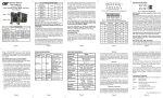
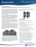
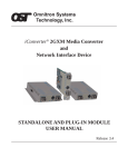
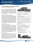
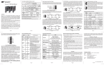
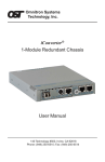
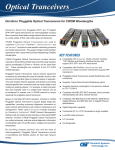
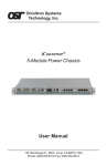
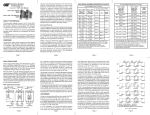
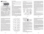
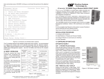
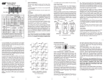
OVERVIEW:
The iConverter 2Fx is a two-port, 100BASE-FX to
100BASE-FX manageable optical switch that retimes and
regenerates the fiber optic signal. It performs error
checking and MAC address learning, and can be used to
daisy chain chassis for distributed networking.
iConverter® 2Fx User Manual
Port 1 (P1)
The 2Fx supports Half-Duplex and Full-Duplex modes
for easy attachment to hubs, switches and workstations.
In addition to the two fiber optic ports, the 2Fx can also
use its two 10/100 backplane ports to connect to adjacent
modules and accommodate flexible network configurations
like in-band management and multi-module configurations.
The iConverter 19-Module, 5-Module or 2-Module Chassis
have backplanes that facilitate connectivity between
adjacent modules.
Port 2 (P2)
iConverter 2Fx
Dual Fiber
Connector Types
Fiber Type
Distance
ST
SC
MM
5 km
8440-0
8442-0
-
SM
30 km
8441-1
8443-1
8447-1
SM
60 km
8441-2
8443-2
8447-2
SM
120 km
-
8443-3
8447-3
LC
iConverter 2Fx
Single-Fiber
Fiber /
Connector
Type
Distance
Tx: 1310 nm
Rx: 1550 nm
Tx: 1550 nm
Rx: 1310 nm
SM / SC
20 km
8450-1
8451-1
SM / SC
40 km
8450-2
8451-2
For wide temperature (-40 to 60º C), add a "W" to the end of the
model number. Consult factory for extended temperature
(-40 to +75º C) models.
When using single-fiber (SF) media converter models, the Tx
wavelength on one end has to match the Rx wavelength on the other.
When the 2Fx’s A and B ports are enabled (using the
“A EN” and “B EN” DIP-Switches), they connect to the
slots on the left and right sides of the 2Fx module via the
chassis’ “A” and “B” backplane links. When other switchbased iConverter modules with backplane port connections
such as a 4-port 10/100 switch module (4Tx) and an NMM
are installed in adjacent slots, they can be connected via
the chassis’ backplane to the 2Fx to facilitate a multimodule configuration.
2Fx Application Example:
Note that using the Advanced Features listed above
requires the use of the NMM or 10/100M and the
NetOutlook™ Management Software, or third-party
SNMP management software or Telnet.
For more information on using and configuring the
Advanced Features, please refer to the NetOutlook
Management Software user manual.
PORT STRUCTURE:
Using a 4-port switch design, the 2Fx features two frontplane fiber ports and two 10/100 Ethernet backplane ports
(A and B) that can connect to adjacent modules within the
same chassis.
LINK MODES:
In order to accommodate different user needs, the
2Fx supports four different linking modes.
In “Link Segment” (LS), sometimes referred to as the
“Normal” mode, a port transmits a “Link” signal
independently of any received “Link” at any other port.
For example, the P1 transmits a “Link” regardless of the
P2 receiving a “Link” [Fig. 2(a) & (b)].
In “Link Propagate” (LP), sometimes referred to as “Link
Loss Carry Forward”, a port transmits a “Link” signal only
when receiving a “Link” at its other port. For example, the
P1 transmits a “Link” only when receiving a “Link” at the
P2 [Fig. 2(c)].
The 2Fx can be used in an unmanaged or managed
fashion. When unmanaged, it can be installed in an
iConverter Chassis without a Network Management Module
(NMM) or iConverter 10/100M. To be managed, an NMM
or 10/100M module must be installed in the same chassis.
Advanced Features:
The 2Fx features Port VLAN and Tag VLAN, which allow
complete control of traffic flow between both fiber ports
and chassis backplane ports on a module, and Port Access
Control, which facilitates enabling and disabling of
individual ports. The 2Fx also supports individual port
bandwidth control and reporting of MIB statistics.
managed or unmanaged media converter to create flexible
and effective network switch configurations. To find out
about individual chassis “A” and “B” backplane links, refer
to the specific chassis’ user manual.
In “Remote Fault Detection” (RFD), the fiber port transmit
a “Link” signal only when receiving a “Link” at the fiber
port. As a result, fiber faults (no “Link” received at the
fiber) are looped-back and can be reported to the network
core [Fig. 2(d)].
Fig. 1 In-Band Managed 2Fx Application
Fig. 1 depicts a chassis with three modules plugged into
three of its adjacent backplane slots. The modules are
connected to the backplane using the A and B backplane
10/100 Ethernet ports. The modules in adjacent slots are
connected to each other via the “A” and “B” backplane
links. The 2Fx in Slot 2 connects to Slot 1 using the “A”
backplane link and to Slot 3 using the “B” backplane link.
In “Remote Fault Detection + Link Propagate” (RFD+LP),
the P2 transmits a “Link” signal only when receiving a
“Link” at the P1. The P1 transmits a “Link” only when
receiving “Link” signals both at the P1 and the P2. As a
result, P1 faults (no “Link” received at the fiber) are
looped-back to the network core and propagated to the
edge [Fig. 2(e)].
Note that connecting two converters with both set to
RFD mode is illegal and will cause a “deadly
embrace” lockup.
In this example, the module in Slot 1 is a Network
Management Module (NMM) and it connects via its “A”
backplane link to the 2Fx in Slot 2, facilitating in-band
management (via the fiber uplink). The module in Slot 3 is
a 4Tx and it connects via its “B” backplane link to the 2Fx
facilitating a 4-port 10/100 Ethernet switch with two fiber
uplinks.
LS
(a)
LS
P1
P2
Switch 2
In “Symmetrical Fault Detection” (SFD), the P2 transmits
a “Link” signal only when receiving a “Link” at the P1. The
P1 transmits a “Link” only when receiving a “Link” signal
both at the P1 and the P2. As a result, P1 faults (no “Link”
received at the fiber) are looped back and can be reported
to the network core. In addition, connecting two back-toback converters which are both set to SFD facilitates
dual-loop-back where P1 faults are reported to both ends
of the network. A blinking fiber link LED indicates a fault
of the transmit P1 or P2 cables of the converter whose
LED is blinking [Fig. 2(f)].
Switch 2
Note that converters in SFD mode must be deployed
in pairs.
P2
P1
Switch 1
Converter A
Converter B
LS
LS
Converter A
LP
Converter B
LP
(b)
Switch 1
DIP-SWITCH SETTINGS:
Front Panel DIP-Switch Settings:
(c)
Switch 1
Converter A
LP
Converter B
RFD
Switch 2
Converter A
LP
Converter B
RFD+LP
Switch 2
(d)
Switch 1
(e)
Switch 1
Converter A
SFD
Converter B
SFD
Switch 2
Converter A
Converter B
Switch 2
Fig. 3 Front Panel DIP-Switches
P1 Fiber Full/Half-Duplex “FDX/HDX” DIP-Switches:
Setting the P1 Fiber Full/Half-Duplex “FDX/HDX”
DIP-Switch to Half-Duplex “HDX” allows for connecting
to a hub (with a shared/non-switched fiber port) or a
workstation that supports only Half-Duplex. Setting
this DIP-Switch to Full-Duplex “FDX” allows for
connecting to a switch or a workstation that supports
Full-Duplex operation.
P2 Fiber Full/Half-Duplex “FDX / HDX” DIP-Switches:
Setting the P2 Fiber Full/Half-Duplex “FDX/HDX”
DIP-Switch to Half-Duplex “HDX” allows for connecting
to a hub (with a shared/non-switched fiber port) or a
workstation that supports only Half-Duplex. Setting
this DIP-Switch to Full-Duplex “FDX” allows for
connecting to a switch or a workstation that supports
Full-Duplex operation.
(f)
Switch 1
LED Lit
LED Blinking
Fig. 2 2Fx Link Modes
LED Off
This example shows how the 2Fx can be used as a traditional
Page 1
Board Mounted DIP-Switch Settings:
Fig. 4 Board Mounted DIP-Switches
A Backplane Enabled “A EN” DIP-Switch:
When the A Backplane Enable “A EN” DIP-Switch is in
the right position, the 2Fx module’s A backplane Ethernet
port is enabled. This port allows connectivity to an
adjacent module via the chassis’ “A” backplane link.
When the “A EN” DIP-Switch is in the left position (factory
default), the 2Fx module’s A backplane Ethernet port is
isolated from the backplane.
B Backplane Enabled “B EN” DIP-Switch:
When the B Backplane Enable “B EN” DIP-Switch is in
the right position, the 2Fx module’s B backplane Ethernet
port is enabled. This port allows connectivity to an
adjacent module via the chassis’ “B” backplane link.
When the “B EN” DIP-Switch is in the left position (factory
default), the 2Fx module’s B backplane Ethernet port is
isolated from the backplane.
Link Propagate/Link Segment “LP” DIP-Switch:
The Link Propagate/Link Segment “LP” DIP-Switch
controls the Link Propagate or Link Segment modes.
When the DIP-Switch is in the right “LP” position, LP
mode is enabled. When the DIP-Switch is in the left
position (factory setting), Link Segment mode is enabled.
Note that for Link Segment mode, “LP”, “RFD” and
“SFD”, DIP-Switches must be in the Left position
(factory setting).
Note that when the “SFD” DIP-Switch is in the Right
position, setting another link mode DIP-Switches
(“LP” and “RFD”) to the Right position on the same
module is an illegal mode that will result in
unpredictable behavior.
Page 7
Page 2
Page 3
Remote Fault Detection “RFD” DIP-Switch:
When this DIP-Switch is in the right “RFD” position, the
Remote Fault Detection mode is enabled. In RFD mode,
the 2Fx propagates the presence or absence of an
incoming “Link” signal from a fiber port receive side to the
transmit side of the fiber port.
4. When using single-fiber (SF) media converter models,
the Tx wavelength on one end has to match the Rx
wavelength on the other. Note that based on this
guideline the SF media converter models must be
used in pairs, such as the 8450-1 matched with the
8451-1.
When this DIP-Switch is in the right “RFD” position and
the “LS/LP” DIP-Switch is in the right “LP” position, Remote
Fault Detection + Link Propagation mode is enabled. In
“RFD+LP” mode, the 2Fx propagates the presence or
absence of an incoming “Link” signal from the P1 receive
side to the transmit side of both the P1 and the P2. In
turn, the presence or absence of an incoming “Link” signal
from the P2 receive side is propagated to the transmit
side of P1.
UPDATING 2FX FIRMWARE:
Note that connecting two converters with both set to
RFD mode is an illegal setting and will cause a
“deadly embrace” lockup.
Symmetrical Fault Detection “SFD” DIP-Switch:
When this DIP-Switch is in the right position, the
Symmetrical Fault Detection “SFD” mode is enabled. In
this mode, two 2Fx media converters can be deployed in
tandem so that the absence of an incoming “Link” signal
on the receive side of any port on either media converter
forces the absence of “Link” signal on all other ports of
both media converters.
MOUNTING AND CABLE ATTACHMENT:
iConverter modules are hot-swappable and can be
installed into any chassis in the iConverter family.
1. Carefully slide the iConverter module into the
installation slot, aligning the module with the
installation guides. Ensure that the module is firmly
seated against the backplane.
2. Secure the module by securing the panel fastener
screw (attached to module) to the chassis front.
Page 4
2FX SPECIFICATIONS:
Model Type
Protocols
Fiber Connectors
Updating the 2Fx firmware requires an iConverter Network
Management Module (NMM) to be installed in the same
chassis. The new 2Fx firmware is uploaded to the NMM’s
FTP server and then installed in the 2Fx.
For more information on updating the 2Fx firmware, please
refer to the NMM user manual.
Controls
2Fx
100BASE-FX
SC, ST, LC
Single-Fiber SC
LS/LP, RFD, SFD,
FDX/HDX, BP Enable
LED Displays
Power, FO link, FDX/HDX
Dimensions
W:0.85" x D:4.5" x H:2.8"
Weight
2FX LED INDICATORS:
LED
Function
"Legend"
Color
Off State
On / Blinking
State
Power "Pwr"
Amber No power
Fiber port 1
duplex
"FDX"
Half-Duplex when
fiber link is active
Full-Duplex when
Green (has no meaning
link fiber is active
when fiber link is not
active)
Fiber port 1
link/activity
"Lk/Act"
Green No fiber link
On: Fiber link
Blinking: Fiber
data transmission
Fiber port 2
duplex
"FDX"
Half-Duplex when
fiber link is active
Full-Duplex when
Green (has no meaning
link fiber is active
when fiber link is not
active)
Fiber port 2
link/activity
"Lk/Act"
On: Fiber link
Blinking: Fiber
data transmission
Green No fiber link
Module has power
8 oz.
Compliance
UL, CE, FCC Class A
Power
Requirement
0.9A @ 3.3VDC (typical)
Temperature
Standard: 0 to 50º C
Wide: -40 to 60º C
Storage: -40 to 80º C
Humidity
5 to 95% (non-condensing)
Altitude
-100m to 4000m
MTBF (hrs)
880,000
Page 6
Warning
The operating description in this Instruction Manual is
for use by qualified personnel only. To avoid electrical
shock, do not perform any servicing of this unit other
than that contained in the operating instructions, unless
you are qualified and certified to do so by Omnitron
Systems Technology, Inc.
Exclusive Remedies
The remedies provided herein are the Buyer’s sole and
exclusive remedies. Omnitron shall not be liable for any
direct, indirect, special, incidental, or consequential
damages, whether based on contract, tort, or any legal
theory.
Warranty
This product is warranted to the original purchaser against
defects in material and workmanship for a period of
TWO YEARS from the date of shipment. A LIFETIME
warranty may be obtained by the original purchaser by
REGISTERING this product with Omnitron within 90
days from the date of shipment. TO REGISTER,
COMPLETE AND MAIL OR FAX THE ENCLOSED
REGISTRATION FORM. Or you may register your
product on the Internet at www.omnitron-systems.com.
During the warranty period, Omnitron will, at its option,
repair or replace a product which is proven to be
defective.
For warranty service, the product must be sent to an
Omnitron designated facility, at Buyer ’s expense.
Omnitron will pay the shipping charge to return the
product to Buyer’s designated US address using
Omnitron’s standard shipping method.
Limitation of Warranty
The foregoing warranty shall not apply to defects
resulting from improper or inadequate use and/or
maintenance of the equipment by Buyer, Buyer-supplied
equipment, Buyer-supplied interfacing, unauthorized
modifications or tampering with equipment (including
removal of equipment cover by personnel not
specifically authorized and certified by Omnitron), or
misuse, or operating outside the environmental
specification of the product (including but not limited to
voltage, ambient temperature, radiation, unusual dust,
etc.), or improper site preparation or maintenance.
No other warranty is expressed or implied. Omnitron
specifically disclaims the implied warranties of
merchantability and fitness for any particular purpose.
3. Attach each fiber port via the appropriate multimode
or single-mode fiber cable to a 100BASE-FX Fast
Ethernet device. The iConverter transmit (Tx) must
attach to the receive side on the other device; the
receive (Rx) must attach to the transmit.
Page 8
Page 5
TECHNICAL SUPPORT:
For help with this product, contact our Technical Support:
Phone:
(949) 250-6510
Fax:
(949) 250-6514
Address:
Omnitron Systems Technology, Inc.
140 Technology Dr.
Irvine, CA 92618 USA
E-mail:
[email protected]
URL:
www.omnitron-systems.com
Form: 040-08440-001D 12/12
Page 9
Page 10
Page 11
Page 12