1
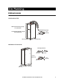
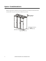
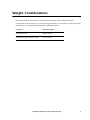
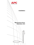
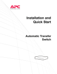
Installation
and Start-up
®
150 kW InfraStruXure
Power Distribution Unit
480 V / 600 V
This manual is available in English on the enclosed CD.
Uživatelská pøíruèka v èeštinì je k dispozici na pøiloženém CD.
Dieses Handbuch ist in Deutsch auf der beiliegenden CD-ROM verfügbar.
Deze handleiding staat in het Nederlands op de bijgevoegde cd.
Este manual está disponible en español en el CD-ROM adjunto.
Ce manuel est disponible en français sur le CD-ROM ci-inclus.
A hasznalati utasitas magyarul megtalalhato a csatolt CD-n.
Questo manuale è disponibile in italiano nel CD-ROM allegato.
本マニュアルの日本語版は同梱の CD-ROM からご覧になれます。
Denne manualen er tilgjengelig på norsk på vedlagte CD.
Instrukcja Obsługi w jezyku polskim jest dostepna na CD.
O manual em Português está disponível no CD-ROM em anexo.
Данное руководство на русском языке имеется на прилагаемом компакт-диске.
Denna manual finns tillgänglig på svenska på medföljande CD.
Bu kullanim kilavuzunun Türkçe'sä, äläxäkte gönderälen CD äçeräsände mevcuttur.
您可以从包含的 CD 上获得本手册的中文版本。
您可以从付属的CD上获得本手册的中文版本。
동봉된 CD 안에 한국어 매뉴얼이 있습니다 .
About This Manual
This manual is intended for APC field service engineers or APC-trained installers of an
InfraStruXure® system. It covers basic installation and start-up procedures.
For information about installing specific components in your InfraStruXure system, see the
documentation included with that component. Before installing or operating any component, refer to
the safety instructions in the component’s manual.
The illustrations of products in this manual may vary slightly from the products in your InfraStruXure
system.
Note
You can check for updates to this manual by clicking on the User Manuals link on the
Support page of the APC Web site (www.apc.com). In the list of InfraStruXure manuals,
look for the latest letter revision (A, B, etc.) of the part number appearing on the back
cover of this manual (990-1983).
150 kW InfraStruXure Power Distribution Unit
i
Contents
Safety .....................................................................1
Overview . . . . . . . . . . . . . . . . . . . . . . . . . . . . . . . . . . . . . . . . . 1
Save these instructions . . . . . . . . . . . . . . . . . . . . . . . . . . . . 1
Safety symbols used in this manual . . . . . . . . . . . . . . . . . . . 1
Cross-reference symbols used in this manual . . . . . . . . . . . . . 1
Warnings . . . . . . . . . . . . . . . . . . . . . . . . . . . . . . . . . . . . . . . . . 2
Receiving/moving . . . . . . . . . . . . . . . . . . . . . . . . . . . . . . . 2
Installation/maintenance . . . . . . . . . . . . . . . . . . . . . . . . . . 2
Maintenance performed while the
PDU is receiving input power . . . . . . . . . . . . . . . . . . . . . . . 2
Total power off procedure . . . . . . . . . . . . . . . . . . . . . . . . . . 3
Emergency Power Off (EPO) . . . . . . . . . . . . . . . . . . . . . . . . 3
EMI . . . . . . . . . . . . . . . . . . . . . . . . . . . . . . . . . . . . . . . . . 4
Site Planning............................................................5
Dimensions . . . . . . . . . . . . . . . . . . . . . . . . . . . . . . . . . . . . . . . . 5
InfraStruXure PDU . . . . . . . . . . . . . . . . . . . . . . . . . . . . . . . 5
NetShelter VX enclosure . . . . . . . . . . . . . . . . . . . . . . . . . . . 5
Space Considerations . . . . . . . . . . . . . . . . . . . . . . . . . . . . . . . . 6
Weight Considerations . . . . . . . . . . . . . . . . . . . . . . . . . . . . . . . 7
Heat Output . . . . . . . . . . . . . . . . . . . . . . . . . . . . . . . . . . . . . . . 8
Electrical Requirements and Specifications . . . . . . . . . . . . . . . . . 9
Electrical requirements . . . . . . . . . . . . . . . . . . . . . . . . . . . . 9
Emergency Power Off (EPO) . . . . . . . . . . . . . . . . . . . . . . . . . . 10
Basic Installation Procedure . . . . . . . . . . . . . . . . . . . . . . . . . . . 11
150 kW InfraStruXure Power Distribution Unit
iii
Installation Procedures .......................................... 13
Level the PDU and NetShelter Enclosures. . . . . . . . . . . . . . . . . 13
Connect the Power Source to the PDU . . . . . . . . . . . . . . . . . . . 14
Access the PDU main input breaker . . . . . . . . . . . . . . . . . . 14
Attach conduit to the PDU for the input conductors . . . . . . . 14
Route the input conductors to the main input breaker . . . . . 16
Torque specs and tools required . . . . . . . . . . . . . . . . . . . . 16
Connect an Emergency Power Off Switch . . . . . . . . . . . . . . . . 17
Overview . . . . . . . . . . . . . . . . . . . . . . . . . . . . . . . . . . . . 17
Connect an EPO switch to the user connection plate
and test the switch . . . . . . . . . . . . . . . . . . . . . . . . . . . . . 18
Safety warnings . . . . . . . . . . . . . . . . . . . . . . . . . . . . . . . 20
Connect User Input Contacts and Relay Outputs
to the User Connection Plate . . . . . . . . . . . . . . . . . . . . . . . . . . 21
Overview . . . . . . . . . . . . . . . . . . . . . . . . . . . . . . . . . . . . 21
To connect and monitor your contacts . . . . . . . . . . . . . . . . 22
Install Shielding Troughs, Shielding Partitions,
and Cable Ladders . . . . . . . . . . . . . . . . . . . . . . . . . . . . . . . . . . 23
Shielding troughs and shielding partitions for
overhead wiring along rows . . . . . . . . . . . . . . . . . . . . . . . 23
Cable ladders for overhead wiring across rows . . . . . . . . . . 24
Install InfraStruXure Rack-Mount Devices . . . . . . . . . . . . . . . . . 25
Install the Rack Automatic Transfer Switches (ATSs) . . . . . . . 25
Install the Rack Power Distribution Units (PDUs) . . . . . . . . . 25
Install the InfraStruXure Manager and Hub (or Switch) . . . . . 25
Install the environmental monitoring unit or
environmental management system . . . . . . . . . . . . . . . . . . 25
Route and Attach Overhead Wiring . . . . . . . . . . . . . . . . . . . . . 26
Wiring Under the Floor . . . . . . . . . . . . . . . . . . . . . . . . . . . . . . 29
Route Data Cables to the
InfraStruXure Manager Hub (or Switch) . . . . . . . . . . . . . . . . . . 31
iv
150 kW InfraStruXure Power Distribution Unit
Start-Up Procedure .................................................33
Safety warnings . . . . . . . . . . . . . . . . . . . . . . . . . . . . . . . 33
Ensure that all power is off . . . . . . . . . . . . . . . . . . . . . . . . 33
Apply power to the system . . . . . . . . . . . . . . . . . . . . . . . . 34
Configure the InfraStruXure Manager .....................37
Appendix A: Operation ..........................................39
How to Apply Power to the System . . . . . . . . . . . . . . . . . . . . . 39
How to Ensure Total Power Off . . . . . . . . . . . . . . . . . . . . . . . . 41
150 kW InfraStruXure Power Distribution Unit
v
Safety
Overview
Save these instructions
This manual contains important instructions that must be followed during installation, operation, and
configuration of the InfraStruXure system.
Safety symbols used in this manual
Electrical
Hazard
Indicates an electrical hazard, which, if not avoided, could result in injury or
death.
Indicates a hazard, which, if not avoided, could result in personal injury or
damage to the product or other property.
Warning
Indicates a potential hazard which could result in damage to product or other property.
Caution
Indicates important information.
Note
Indicates a heavy load that should not be lifted without assistance.
Heavy
Indicates a standby state. When in standby, the unit is not operating (although it may
still contain hazardous voltage). Equipment that has been placed in standby is not safe
to service. It must first be disconnected from all sources of electrical power.
Cross-reference symbols used in this manual
Indicates that more information is available on the same subject in a different section of
this manual.
Indicates that more information is available on the same subject in a different manual.
See also
150 kW InfraStruXure Power Distribution Unit
1
Warnings
Receiving/moving
Do not tilt the PDU more than 45° from its vertical axis. Never lay the PDU on its side.
Installation/maintenance
Only a certified electrician can:
• Connect the PDU to its power source
• Connect a switch to the EPO interface on the PDU
• Install a customer-specified, hard-wired power cable
Only a certified electrician or an APC field service engineer can perform maintenance on the PDU.
When connecting the PDU to its power source, you must install a circuit breaker to protect the PDU
against over-current conditions. Determine the type of circuit breaker you need to install. If using the
PDU at its full rating, the following circuit breaker sizes are recommended:
Input Voltage
Circuit Breaker Size
480 V
250 A
600 V
200 A
Maintenance performed while the PDU is receiving input power
APC does not recommend that you perform maintenance on the PDU while it is receiving input
power. However, due to the critical nature of data center loads, this may occur. If you must perform
maintenance while the PDU is receiving input power, observe the following precautions to reduce the
risk of electric shock:
1. Never work alone.
2. Perform the maintenance only if you are a certified electrician who is trained in the hazards of
live electrical installation.
3. Know the procedure for disconnecting electricity to the PDU and the data center in case of an
emergency.
4. Wear appropriate personal protective equipment.
5. Use double-insulated tools.
6. Always follow local and site regulations when working on the PDU.
2
150 kW InfraStruXure Power Distribution Unit
Safety: Warnings
Total power off procedure
1. Open (turn OFF) the main input breaker on the PDU.
2. Open (turn OFF) the main circuit breaker for the power source feeding the PDU.
Emergency Power Off (EPO)
Hazardous voltage from the branch circuit must be isolated from the 24 VAC, 24 VDC, and contact
closure terminals. 24 VAC and 24 VDC are considered Class 2 circuits as defined in Article 725 of
the National Electrical Code (NFPA 70) and Section 16 of the Canadian Electrical Code (C22.1).
A Class 2 circuit is a source having limited voltage and energy capacity as follows:
a. If an Inherently Limited Power Source, voltage and energy are limited to less than 30 VAC,
less than 30 VDC, and 8 A.
b. If not an Inherently Limited Power Source, voltage and energy are limited to less than
30 VAC, less than 60 VDC, 250 VA, and current is limited to 1000/Vmax. The fuse is
limited to 5 A if less than 20 VAC or 20 VDC, or 100/Vmaximum if less than 30 VAC or
60 VDC.
If choosing a 24 VAC, 24 VDC, or contact closure connection to the EPO, use one of the following
UL-listed wire types:
• CL2 Class 2 cable for general purpose use
• CL2P Plenum cable for use in ducts, plenums, and other space used for environmental air
• CL2R Riser cable for use in a vertical run shaft from floor to floor
• CL2X Limited Use cable for use in dwellings and for use in a raceway
• For installations in Canada, the cable should be CSA-certified, type ELC (extra-low-voltage
control cable).
If not using CL2 cable, route the EPO wiring in conduit that does not contain any branch circuit
wiring.
150 kW InfraStruXure Power Distribution Unit
3
Safety: Warnings
EMI
This equipment has been tested and found to comply with the limits for Class A digital devices,
pursuant to Part 15 of the FCC Rules. These limits are designed to provide reasonable protection
against harmful interference when the equipment is operated in a commercial environment. This
equipment generates, uses, and can radiate radio frequency energy and, if not installed and used in
accordance with this user manual, may cause harmful interference to radio communications.
Operation of this equipment in a residential area is likely to cause harmful interference. The user will
bear sole responsibility for correcting such interference.
This Class A digital apparatus complies with Canadian ICES-003.
Cet appareil numérique de la classe A est conforme à la norme NMB-003 du Canada.
4
150 kW InfraStruXure Power Distribution Unit
Site Planning
Dimensions
InfraStruXure PDU
Without PDU Shielding Trough
81 in (2060 mm)
PDU Shielding Trough
Including PDU Shielding Trough
7.2 in
(183 mm)
88.2 in (2240 mm)
23 in (584 mm)
36 in (910 mm)
29in (710mm)
NetShelter VX enclosure
Shielding Partitions
23.5 in
(597 mm)
81.5 in
(2070 mm)
4.8 in
(122 mm)
7.2 in
(183 mm)
23.5 in
(597 mm)
23.5 in
(597 mm)
42.2 in
(1072 mm)
150 kW InfraStruXure Power Distribution Unit
5
Space Considerations
Study the figure below to determine your space requirements for installing the InfraStruXure PDU.
Consult the NEC and your local codes for additional requirements.
Ceiling Clearance
>12 in (304 mm)
Minimum Rear Clearance
42 in (1067 mm)
Minimum Front Clearance
42 in (1067 mm)
6
150 kW InfraStruXure Power Distribution Unit
Weight Considerations
Ensure that the floor and sub-floor can support the total weight of the configuration when
concentrated on the leveling feet. If you are placing equipment on a raised floor, consult the flooring
manufacturer for loading requirements before installing equipment.
Component
Maximum Weight
InfraStruXure PDU
2000 lb (907 kg)
NetShelter VX base enclosure (empty)
351 lb (160 kg)
150 kW InfraStruXure Power Distribution Unit
7
Heat Output
Consider the heat dissipation ratings of equipment to determine cooling requirements. Additional
cooling equipment may be required. The heat output of the 150 kW InfraStruXure PDU is
9980 BTU/hr (2.92 kW/hr).
8
150 kW InfraStruXure Power Distribution Unit
Electrical Requirements and Specifications
Electrical requirements
480 V
600 V
Service distribution breaker†‡
250 A
200 A
Conductors to main input breaker†
3W + G + GEC
3W + G + GEC
L1, L2, L3
4/0 AWG
3/0 AWG
G
4 AWG
6 AWG
GEC
2 AWG
4 AWG
Recommended wire sizing
‡
† Provided by customer. Copper conductors only!
‡ The specifications are recommendations only. Consult the NEC and local codes for requirements specific to your
installation.
150 kW InfraStruXure Power Distribution Unit
9
Emergency Power Off (EPO)
Overview
Note
The main input breaker on the PDU is equipped with a shunt trip for emergency power
off. The shunt trip can be activated for EPO functionality by connecting an appropriate
power source (24 VAC or 24 VDC) to the EPO interface on the user connection plate.
To provide a mechanism for applying emergency power off, attach a remote switch to the EPO
interface on the user connection plate. The EPO interface () is connected to the PDU monitoring
unit () by way of the user connection plate, which in turn connects to the main input breaker on the
PDU and to the internal EPO switch on an APC UPS or other APC-connected device ().
When EPO is activated, the main input breaker on the PDU opens (turns OFF). In addition, the enable
switch on the UPS opens (turns OFF) and the DC disconnect breakers serving the UPS open (turn
OFF). The last two actions negate power to the PDU from the UPS inverters and batteries.
APC offers an optional InfraStruXure EPO system (EPW9). Contact your APC sales
representative, or visit the APC Web site (www.apc.com) for more information.
Note
See “Connect an Emergency Power Off Switch” on page 17 for instructions on how to
connect an EPO switch to the PDU.
10
150 kW InfraStruXure Power Distribution Unit
Basic Installation Procedure
This section provides basic instructions for installing InfraStruXure power and rack components.
Follow the references provided with each step for more detailed instructions.
Do not begin installing your InfraStruXure system without an APC field service
engineer present.
Warning
1. Unpack the components according to the unpacking instructions included on the outside of the
packaging or in the component’s manual.
Search all boxes and packaging to make sure they are empty before discarding.
Note
2. Determine the correct placement of your system components by studying your InfraStruXure
Configure-To-Order (CTO) report. Move the InfraStruXure PDU and NetShelter VX enclosures
to their final location.
Warning
If installing your system on a raised floor, make sure the raised-floor
structure has a lb/in² rating that will support the full weight of the
installation. See “Weight Considerations” on page 7.
3. Level the PDU and NetShelter enclosures using the 13/14-mm wrench included with each unit.
See page 13 for detailed instructions.
4. Join adjacent NetShelter enclosures.
For instructions on joining adjacent NetShelter VX enclosures, see the
installation manual included with these enclosures.
See also
5. Ensure total power off.
See page 33 for detailed instructions.
6. Connect the power source to the PDU.
A licensed electrician must connect the power source.
See page 14 for detailed instructions.
150 kW InfraStruXure Power Distribution Unit
11
Site Planning: Basic Installation Procedure
7. Connect an EPO switch to the PDU monitoring unit.
See page 17 for detailed instructions.
8. Install shielding troughs, shielding partitions, and cable ladders.
For instructions, see the manuals included with your shielding troughs,
shielding partitions, and cable ladders.
See also
9. Install the Rack Automatic Transfer Switches (ATSs), the Rack Power Distribution Units
(PDUs), and other InfraStruXure rack-mount devices.
See also
For instructions, see the manuals included with your rack automatic
transfer switches, rack power distribution units, and other
InfraStruXure rack-mount devices.
10. Route and attach power cables to each rack ATS and/or rack PDU.
See page 25 for detailed instructions.
11. Route and attach communication cables to the InfraStruXure Manager Hub (or Switch).
See page 31 for detailed instructions.
12. Start the system.
Only qualified, APC-trained personnel may perform a system start-up.
See page 33 for detailed instructions.
13. Configure the InfraStruXure Manager.
For instructions, see the manual included with your InfraStruXure Manager.
See also
12
150 kW InfraStruXure Power Distribution Unit
Installation Procedures
Level the PDU and NetShelter Enclosures
Leveling feet are provided under each bottom corner of the enclosure to help provide a stable base if
the selected floor space is uneven. However, leveling feet are not intended to compensate for a badly
sloped surface. To level the enclosure:
1. Fit the 14-millimeter end of the open-ended wrench (provided) to the hex head just above the
round pad on the bottom of the leveling foot. Turn the wrench clockwise to extend the leveling
foot until it makes firm contact with the floor.
2. Repeat step 1 for each of the remaining leveling feet.
3. Use a level to determine which feet need further adjustment to level the enclosure. Adjust as
necessary.
150 kW InfraStruXure Power Distribution Unit
13
Connect the Power Source to the PDU
Access the PDU main input breaker
Open the back doors of the PDU by first unlocking the smaller door on top using the provided key,
and then loosening the two screws holding the bottom half of this door in place.
Attach conduit to the PDU for the input conductors
1. Remove the top or bottom rectangular gland plate by loosening the captive screws using a
Phillips or standard screwdriver:
– For wiring under a raised floor: Remove the gland plate at the bottom of the PDU.
14
150 kW InfraStruXure Power Distribution Unit
Installation Procedures: Connect the Power Source to the PDU
– For overhead wiring: Remove the gland plate on the roof of the PDU, and then detach the
user connection plate from the gland plate, route the user connection plate through the
opening left by the gland plate, and then carefully set the user connection plate aside on top
of the enclosure (do not disturb the connected wires).
2. Use a knock-out punch to create an appropriatesized hole in the gland plate for the conduit.
3. Install a lock-nut and bushing to the conduit.
4. Thread the conduit through the hole.
5. Re-attach the user connection plate to the gland
plate.
6. Re-attach the gland plate to the PDU enclosure.
150 kW InfraStruXure Power Distribution Unit
15
Installation Procedures: Connect the Power Source to the PDU
Route the input conductors to the main input breaker
Route the input conductors to the main input breaker on the PDU and connect the input wiring
according to the labels on the breaker and the following illustration. Refer to the table below (Torque
specs and tools required) for specific information about connecting to each terminal.
Connect the conductors to the terminals according to the labels on the terminals.
Use copper conductors only.
Warning
3-phase, 3-wire + ground + GEC to building steel*
G
L1 L2 L3
GEC
C
*Other
types of electrodes may be used if building steel is not available. Consult the NEC for
requirements.
Torque specs and tools required
Before connecting to the terminals, verify the torque specs below by checking the specifications on
the main input breaker.
16
Terminal
Torque
Tools
L1, L2, L3
150 in-lb (17 Nm)
6-mm Allen wrench
G
4–6 AWG: 45 in-lb (5.0 Nm)
Slotted screwdriver
GEC
2-4 AWG: 50 in-lb (5.6 Nm)
Slotted screwdriver
150 kW InfraStruXure Power Distribution Unit
Connect an Emergency Power Off Switch
APC offers an optional InfraStruXure EPO system (EPW9). Contact your APC sales
representative or visit the APC Web site (www.apc.com) for more information.
Note
If you are not connecting an emergency power off switch to the PDU, leave the
Arm/Test rocker switch on the PDU monitoring unit in the Test position.
Caution
Note
The PDU monitoring unit provides the EPO function. The purpose of this function
is to activate any shunt trips controlled by the PDU monitoring unit in emergency
situations. Shunt trips are present on the main input breaker of the PDU and on
breakers that support the power source feeding the PDU.
Overview
Connecting the switch. The
4
Contact Outputs
ATS 1
2
3
Contact Inputs
ATS 2
1
ATS 0
USER INTERFACE
© 2001 APC
MADE IN USA
ATS EN
Emergency Power Off (EPO) switch
connects to the user connection plate. The
figure on the right shows the location of
the user connection plate on the roof of the
PDU. Three types of EPO connections are
available on this plate:
– +
EPO 24V EPO
AC/DC Contact
• Contact closure
• 24 VAC
• 24 VDC
Contact closure is recommended.
Note
Configuring and testing. Configuring and
testing of the switch is done through the EPO
interface on the PDU monitoring unit. The
figure on the right shows the PDU monitoring
unit and the location of the EPO LEDs and DIP
switches.
150 kW InfraStruXure Power Distribution Unit
17
Installation Procedures: Connect an Emergency Power Off Switch
Connect an EPO switch to the user connection plate and test the switch
1. Connect the switch to the appropriate EPO connection points in the terminal block on the user
connection plate. Read the label next to the terminal block to determine which connection
points apply to your signal type:
– Contact Closure—Normally Open
USER INTERFACE
© 2001 APC
MADE IN USA
Contact Outputs
ATS EN
4
ATS 1
2
3
Contact Inputs
ATS 2
1
ATS 0
External Set of
Normally Open Dry Contacts
– +
EPO 24V EPO
AC/DC Contact
– Contact Closure—Normally Closed
USER INTERFACE
© 2001 APC
MADE IN USA
Contact Outputs
ATS EN
4
ATS 1
2
3
Contact Inputs
ATS 2
1
ATS 0
External Set of
Normally Closed Dry Contacts
– +
EPO 24V EPO
AC/DC Contact
– 24 VAC/VDC—Normally Open
External Set of Normally Open Dry Contacts
USER INTERFACE
© 2001 APC
MADE IN USA
ATS 2
Contact Outputs
ATS EN
4
ATS 1
2
3
Contact Inputs
ATS 0
1
24 V AC or DC Power Supply
– +
EPO 24V EPO
AC/DC Contact
Normally Closed
2. Verify that the EPO DIP switches on the PDU monitoring unit are configured properly for your
signal type. The labels above the switches and the figure below show the correct settings for
both the Normally Open (NO) and Normally Closed (NC) positions.
TRIPPED
Location of switches
on PDU monitoring unit
NC
TEST
NO
Normally Open
or 24V AC/DC
EPO
ARMED
The default setting on the EPO interface is for a Normally Open (NO) switch.
Note
18
150 kW InfraStruXure Power Distribution Unit
Installation Procedures: Connect an Emergency Power Off Switch
3. Test the EPO switch to ensure it is wired correctly and working properly:
a. Place the Arm/Test rocker in the Test position. The EPO state LEDs will be off and the PDU
display interface will show the following alarm (in addition to any other active alarms):
Active Alarm xxofxx
EPO Ready To Test
b. Engage the EPO switch (if your switch is momentary, engage it while one person is watching
the EPO state LEDs and another is at the EPO switch).
c. Observe the EPO LEDs. If the switch is wired correctly and working properly, both of the
EPO state LEDs will light red when the switch is engaged.
d. If the test was successful, place the Arm/Test rocker back to the Arm position. The PDU
display interface will clear the EPO test mode alarm. If the test was not successful, refer to
the following troubleshooting chart:
Problem
Action
Neither state LED was lit red when the
EPO switch was engaged.
• Check the wiring to the EPO switch.
• Check to make sure the EPO DIP switch
configuration is correct for your switch (NO or
NC). See step 2 on the previous page for proper
configuration instructions.
Only one of the state LEDs was lit red
when the EPO switch was engaged.
• Check to make sure the EPO DIP switch
configuration is correct for your switch (NO or NC)
and retest. See step 2 on the previous page for
proper configuration instructions.
• If the switch is configured correctly and both LEDs
still do not light red after retesting, contact
customer support at a number appearing on the
back cover of this manual.
e. Repeat this test for each EPO switch installed.
4. Ensure that the Arm/Test rocker is in the Arm position on the monitoring unit.
150 kW InfraStruXure Power Distribution Unit
19
Installation Procedures: Connect an Emergency Power Off Switch
Safety warnings
Hazardous voltage from the branch circuit must be isolated from the 24 VAC, 24 VDC, and contact
closure terminals. 24 VAC and 24 VDC are considered Class 2 circuits as defined in Article 725 of
the National Electrical Code (NFPA 70) and Section 16 of the Canadian Electrical Code (C22.1).
A Class 2 circuit is a source having limited voltage and energy capacity as follows:
a. If an Inherently Limited Power Source, voltage and energy are limited to less than 30 VAC,
less than 30 VDC, and 8 A.
b. If not an Inherently Limited Power Source, voltage and energy are limited to less than
30 VAC, less than 60 VDC, 250 VA, and current is limited to 1000/Vmax. The fuse is
limited to 5 A if less than 20 VAC or 20 VDC, or 100/Vmaximum if less than 30 VAC or
60 VDC.
If choosing a 24 VAC, 24 VDC, or contact closure connection to the EPO, use one of the following
UL-listed wire types:
• CL2 Class 2 cable for general purpose use
• CL2P Plenum cable for use in ducts, plenums, and other space used for environmental air
• CL2R Riser cable for use in a vertical run shaft from floor to floor
• CL2X Limited Use cable for use in dwellings and for use in a raceway
• For installations in Canada, the cable should be CSA-certified, type ELC (extra-low-voltage
control cable).
If not using CL2 cable, route the EPO wiring in conduit that does not contain any branch circuit
wiring.
20
150 kW InfraStruXure Power Distribution Unit
Connect User Input Contacts and Relay
Outputs to the User Connection Plate
Overview
4
Contact Outputs
ATS 1
2
3
Contact Inputs
ATS 2
1
ATS 0
USER INTERFACE
© 2001 APC
MADE IN USA
ATS EN
Make contact closure connections
(NO or NC) at the user connection
plate to monitor dry contacts. You
can make up to eight
connections—four input contacts
and four relay outputs.
– +
EPO 24V EPO
AC/DC Contact
The figure on the right shows the
location of the user connection
plate on the roof of the PDU
enclosure.
You can make connections from
inside the enclosure, or you can
remove the user connection plate to
make your connections.
Remove the plate using a Phillips
or standard screwdriver to loosen
the two captive screws. Use the
knockout in the plate to route
cables to and from the user
connections on the plate. If
removing the plate, make sure you
do not disturb the existing
connections.
150 kW InfraStruXure Power Distribution Unit
21
Installation Procedures: Connect User Input Contacts and Relay Outputs to the User Connection Plate
To connect and monitor your contacts
1. Choose one or more contact numbers on the User/EPO contacts port on the user connection
plate. The user connection plate connects to the PDU monitoring unit.
2. From the PDU display interface:
a. Press ESC or ENTER to go to the top-level menu screen.
b. Select Contacts from the top-level menu screen and press ENTER.
Load-Meter
Volt-Meter
Contacts
Breakers
Alarms
Panel
Config
Help
c. Select Contact Inputs (or Relay Outputs) and press ENTER to display the contact inputs (or
relay outputs) screen.
d.
>Contact Inputs
>Relay Outputs
>Alarm Relay Map
d. Select Contact In and press ENTER to select the number of the contact you are connecting.
The continue arrow will appear next to the contact number. Press the Up or Down arrow to
go to the appropriate contact number and press ENTER.
Contact In:01of04
Name: User Contact1
Normal:Open
Status: Closed
e. Press the Down arrow to enter a unique Name for the contact and to configure the Normal
state of the contact (Open or Closed). The default Normal state is Open. Press ENTER.
You will be prompted for your password.
Note
3. Connect contact wires (300 V-rated cabling required) to the terminal block on the user
connection plate. Use a 2.5-mm standard screwdriver.
4. Run the wires from the terminal block out the roof or under the floor of the PDU to your
contacts.
Ensure the wires are properly retained and kept away from
high-voltage lines and breakers.
Warning
See the “Specifications” section in the InfraStruXure PDU Operation
and Configuration manual (990-1984) for relay output specifications.
See also
22
150 kW InfraStruXure Power Distribution Unit
Install Shielding Troughs, Shielding
Partitions, and Cable Ladders
Shielding troughs and shielding partitions for overhead wiring along rows
If you ordered APC shielding troughs, shielding partitions, and cable ladders to route overhead
wiring for your system, assemble the shielding troughs and the shielding partitions along the rows of
enclosures and assemble the cable ladders between rows.
For information on grounding the shielding troughs and shielding partitions, see the
instruction sheet included with the shielding troughs and shielding partitions.
See also
Shielding Troughs. There are two types of shielding troughs:
• The PDU shielding trough is 24 in (610 mm) long (non-adjustable). It sits on top of the
InfraStruXure PDU and accommodates power cables as they exit the roof of the PDU.
• The NetShelter shielding trough is 24 in (610 mm) long (non-adjustable). It has an opening in
each side through which you can route data cables to the shielding partitions.
Shielding trough accessories. APC offers the following accessories for shielding troughs:
• Shielding trough covers for both 24-in (600-mm) wide (AR8174BLK) and 30-in (750-mm)
wide (AR8175BLK) enclosures. Contact APC for more information.
• Shielding trough end caps (AR8167BLK) to place on the side of a shielding trough that is
located at the end of a row. Contact APC for more information.
150 kW InfraStruXure Power Distribution Unit
23
Installation Procedures: Install Shielding Troughs, Shielding Partitions, and Cable Ladders
Shielding partitions. Shielding partitions form the side wall of a trough. You can customize the
width of the trough for each row in your system by making it wider for rows carrying many data
cables and narrower for rows carrying fewer cables. There are two types of shielding partitions:
• As the back wall, use a shielding partition that
contains an opening for routing data cables.
• As the front wall, use a solid shielding partition to
hide data cables for a clean appearance.
Cable ladders for overhead wiring across rows
After installing the shielding toughs and shielding partitions, install the cable ladders between rows
of enclosures. You can also run cable ladders across shielding troughs in the same row using the
hardware provided in the ladder kit.
For more information on installing cable ladders, see the instruction sheet included with
the cable ladders.
See also
Use the wide 12-inch (305 mm) cable ladders in instances where many power cables or data cables
will run between rows, and use the narrow 6-inch (152 mm) cable ladders in instances where fewer
power cables or data cables will run between rows.
The cable ladders are 116 inch (2946 mm) long. You can adjust the length of the cable ladders in the
following ways:
• Cut off the ends with a hacksaw to shorten them.
• Insert the connectors only partially into the side rails to extend them.
Note
24
Do not change the spacing between rows or the length and position of the cable ladders
from the layout you planned with your APC representative. For overhead wiring, each
PDU power cable is provided at a pre-determined length. Changes to the physical
configuration of your system could cause some power cables to be too short or too long.
150 kW InfraStruXure Power Distribution Unit
Install InfraStruXure Rack-Mount Devices
Install the Rack Automatic Transfer Switches (ATSs)
Install a rack ATS in the top of each enclosure for overhead wiring, and in the bottom of each
enclosure for under-floor wiring.
See the installation instructions in the manual included with your rack ATS.
See also
The rack ATS is an optional component, and is not included with all InfraStruXure systems.
Install the Rack Power Distribution Units (PDUs)
Install rack PDUs in the rear of the NetShelterVX enclosure, in the channel directly behind the rear
vertical mounting rails. For overhead wiring, make sure the power cord is pointing toward the roof of
the enclosure. For under-floor wiring, make sure the power cord is pointing toward the floor.
See the installation instructions in the manual included with your rack PDU.
See also
Install the InfraStruXure Manager and Hub (or Switch)
Install the InfraStruXure Manager in the enclosure located closest to the PDU. The CAT-5 data cables
included with your configuration are of varying lengths, based on the distance components will be
installed from the PDU.
See the installation instructions in the manual included with your InfraStruXure
Manager.
See also
Install the environmental monitoring unit or environmental management system
The environmental monitoring unit and the environmental management system are optional
components, and are not included with all InfraStruXure systems.
See the installation instructions in the manual included with your environmental
monitoring unit or environmental management system.
See also
150 kW InfraStruXure Power Distribution Unit
25
Route and Attach Overhead Wiring
Route and attach power cables to equipment racks
If you ordered overhead wiring, connect the prewired power cables from the PDU as follows:
1. Install the shielding troughs, shielding partitions, and cable ladders in such a way as to allow
you to route power cables from the PDU to each of the NetShelter VX enclosures.
For installation instructions, see the manual included with your shielding troughs,
shielding partitions, and cable ladders.
See also
2. Locate the numbers indicating the enclosure to which each power cable will supply power.
These numbers should appear on the roof of the PDU (where the power cables exit the
enclosure), and on the ends of each power cable.
The enclosures are not numbered. Consult your InfraStruXure Configure-To- Order
(CTO) report to determine the enclosure associated with each power cable.
Note
3. Beginning with the enclosures farthest from the PDU: Run each power cable (within the
shielding trough) along the row and, if necessary, across one or more cable ladders to the
enclosure to which it will provide power.
Ensure that the L21-20 twist-lock connector at the end of each power cable always lies
on top of any longer power cables in the shielding trough.
Note
4. Connect the appropriate power cable to APC power management equipment in the enclosure in
one of four ways:
– For single-feed devices without redundancy: Attach a power cable directly to a rack PDU
installed in a NetShelter VX enclosure.
26
150 kW InfraStruXure Power Distribution Unit
Installation Procedures: Route and Attach Overhead Wiring
– For dual-feed devices within a redundant system: Attach a power cable from each PDU to
two different rack PDUs in the NetShelter VX enclosure.
– For single-feed devices within a redundant system with an automatic transfer switch:
Connect a power cable to the automatic transfer switch (A and B feeds) and connect the
automatic transfer switch power cord to a rack PDU in the NetShelter VX enclosure.
– For dual-feed devices in a redundant system with an automatic transfer switch: Connect a
power cable from each PDU to the automatic transfer switch’s A and B feeds, and another
power cable from one PDU to a rack PDU, and the automatic transfer switch power cord to a
second rack PDU in the NetShelter VX enclosure.
Lay the cables neatly in the shielding trough to minimize cable build-up.
Note
150 kW InfraStruXure Power Distribution Unit
27
Installation Procedures: Route and Attach Overhead Wiring
5. From each NetShelter VX enclosure, run the power cable for an APC power management
device out the roof and through the notch in the rear side of the shielding trough to the
connector of the appropriate power cable from the PDU. Plug the two connectors together, and
then twist them clockwise to lock.
Note
28
The APC InfraStruXure build-out tool allows you to attach three 20 A, single-pole
breakers to one three-phase power cable if powering 120 V (L-N) loads, or one threephase power cable to one three-pole 20 A breaker if powering 280 V (L-L) loads.
150 kW InfraStruXure Power Distribution Unit
Wiring Under the Floor
Electrical
Hazard
A licensed electrician must route and connect the power cables for under-floor
wiring.
Make sure all wire connections and circuit breaker connections are properly
torqued.
Warning
If routing power cables to enclosures under a raised floor, you must provide the appropriate power
cables and equipment for installation, and a licensed electrician must route and connect the power
cables to the PDU circuit breakers. To wire each power cable to an enclosure:
1. Remove a knock-out filler in the floor of the PDU to create an opening for the cable.
2. Install Liquidite waterproof conduit under the floor from each enclosure to the PDU.
3. From the rack PDU or rack ATS in each enclosure, thread the appropriate power cable (for your
application) through the Liquidite conduit to the PDU.
4. At the PDU, route the cable through the opening you created in step 1 and then through the
wireway for connection to the upper circuit breaker distribution panel.
150 kW InfraStruXure Power Distribution Unit
29
Installation Procedures: Wiring Under the Floor
5. At the distribution panel, cut the power cable to the proper length and connect the individual
wires:
a. If branch current monitoring is installed, route each phase conductor through a current
sensor. If using three-phase cable, route the L1, L2, and L3 wires through a separate current
sensor.
b. Connect the L1, L2, and L3 wires to the circuit breaker(s). The following illustration shows a
three-phase cable connecting to three single-pole breakers; however, you can also connect a
three-phase cable to a three-pole breaker, or a single-phase cable to a single-pole breaker.
c. Connect the neutral wire to the closest open termination point on the Neutral Bar (N).
d. Connect the ground wire to the closest open termination point on the Ground Bar (G).
N
G
The following table provides specific information about connecting to each terminal.
Terminal
Copper Conductor Size (AWG)
Torque
Tool
L1, L2, L3
8, 10, 12
36 lb-in (4 Nm)
Slotted screwdriver
N, G
8, 10, 12
20 lb-in (2.3 Nm)
Slotted screwdriver
Note
30
Any customer-specified, hard-wired, multi-circuit power cable that is installed by
an electrical contractor must include a circuit breaker which provides both
automatic and manual disconnection of all non-grounded circuit conductors.
150 kW InfraStruXure Power Distribution Unit
Route Data Cables to the InfraStruXure
Manager Hub (or Switch)
1. Connect a CAT-5 network cable (provided) to the designated 10 Base-T ports on your APC
InfraStruXure devices. The following devices need to be connected:
Automatic Transfer Switch
Rack PDU
Environmental Monitoring Unit
InfraStruXure PDU
2. Route the connected CAT-5 network cables through the data cable troughs to the InfraStruXure
Manager Hub (or Switch).
3. Connect each device’s network cable to any available station port in the InfraStruXure Manager
Hub (or Switch). Station ports are those with an x after the number (e.g., 2x).
150 kW InfraStruXure Power Distribution Unit
31
Start-Up Procedure
Safety warnings
This section provides instructions on how to perform a system start-up. Do not skip any steps in this
procedure.
Electrical
Hazard
Electrical
Hazard
Only APC field service engineers or qualified, APC-trained personnel may
perform a system start-up
Before proceeding with system start-up, ensure power is off by following the
instructions below.
Ensure that all power is off
1. Open (turn OFF) the main input breaker on
the PDU.
2. Open (turn OFF) the main circuit breaker for
the power source feeding the PDU.
150 kW InfraStruXure Power Distribution Unit
33
Start-Up Procedure
3. Open (turn OFF) the main output breaker on the front of the PDU.
Apply power to the system
1. Close (turn ON) the main circuit breaker for the power source feeding the PDU.
2. Close (turn ON) the main input breaker on the PDU.
3. Verify that the proper voltage is present on the secondary winding of the transformer (208 V,
metered phase-to-phase) using a true RMS voltmeter.
34
150 kW InfraStruXure Power Distribution Unit
Start-Up Procedure
4. Close (turn ON) the main output breaker on the front of the PDU.
When the main output breaker is closed (turned ON), both PDU distribution panels
are energized.
Note
5. Close (turn ON) the individual PDU distribution panel circuit breakers.
When the distribution panel circuit breakers are closed (turned ON), the PDU power
cables and connected equipment are energized.
Note
150 kW InfraStruXure Power Distribution Unit
35
Start-Up Procedure
6. Close (turn ON) all sub-feed breakers (if applicable).
36
150 kW InfraStruXure Power Distribution Unit
Configure the InfraStruXure Manager
Once all equipment is installed, network cables have been connected to the InfraStruXure Manager
Hub (or Switch), and start-up of the system is complete, configure the InfraStruXure Manager.
For instructions, see the Installation and Quick-Start manual included with your
InfraStruXure Manager.
See also
If using PowerChute Network Shutdown (PCNS) software with your InfraStruXure
UPS, your UPS must have a connection to the “User LAN” (public network) in order
for PCNS to function properly.
Note
If the network management card installed in your UPS is connected to the
InfraStruXure Manager’s “APC LAN,” you must install a second network
management card in your UPS and connect it to the “User LAN” (public network) in
order to use PCNS.
150 kW InfraStruXure Power Distribution Unit
37
Appendix A: Operation
How to Apply Power to the System
This procedure provides instruction for re-applying power to an already installed system. For initial
start-up instructions, see “Start-Up Procedure” on page 33.
1. Close (turn ON) the main circuit breaker for
the power source feeding the PDU.
2. Close (turn ON) the main input breaker on
the PDU.
3. Power the PDU distribution circuit breakers.:
a. Close (turn ON) the main output breaker
on the front of the PDU.
When the main output circuit breaker is closed (turned ON), both PDU distribution
panels are energized.
Note
150 kW InfraStruXure Power Distribution Unit
39
Appendix A: Operation
b. Close (turn ON) the individual PDU
distribution panel circuit breakers.
When the distribution panel circuit breakers are closed (turned ON), the PDU power
cables and connected equipment are energized.
Note
c. Close (turn ON) all sub-feed breakers (if applicable).
40
150 kW InfraStruXure Power Distribution Unit
How to Ensure Total Power Off
1. Open (turn OFF) the main circuit breaker for
the power source feeding the PDU.
2. Open (turn OFF) the main input breaker on
the PDU.
3. Open (turn OFF) the main output breaker
on the front of the PDU, and all sub-feed
circuit breakers (if applicable).
150 kW InfraStruXure Power Distribution Unit
41
Index
A
Applying power to the system 33–
34, 37–38
Automatic transfer switches,
installing 25
C
Cable ladders, installing 24
Ceiling clearance 6
Circuit breaker size 2
D
Dimensions
InfraStruXure PDU 5
NetShelter VX enclosure 5
E
Electrical requirements 9
Emergency power off (EPO)
connecting the switch 17–20
overview 10
problems with 19
safety warnings 20
EMI warnings 4
Environmental management
system, installing 25
Environmental monitoring unit,
installing 25
F
M
Front clearance, minimum value 6
I
InfraStruXure Manager
configuring the 35
installing 25
routing data cables to the 30
InfraStruXure PDU
dimensions 5
electrical requirements 9
heat output 8
level the 13
maximum weight 7
Input conductors
attaching conduit for the 14–15
routing to the main input circuit
breaker 16
Input contacts
connect to the user connection
plate 21–22
Installation 13–30
connect the power source 14–16
connect user input contacts and
relay outputs 21–22
connecting an EPO switch 17–
20
install shielding troughs,
shielding partitions, and cable
ladders 23–24
level the PDU and NetShelter
enclosures 13
overview of basic procedure 11–
12
rack-mount devices 25
route and attach overhead wiring
26–28
warnings for 2
wiring under the floor 29
Main input breaker, accessing the 14
Maintenance, warnings 2
Moving the PDU, warnings 2
N
NetShelter VX enclosure
dimensions 5
level the 13
maximum weight 7
O
Operation 37–39
P
Power cables, routing to equipment
racks 26–28
Power source, connecting to the
PDU 14–16
R
Rack PDUs, installing 25
Rear clearance, minimum value 6
Receiving the PDU, warnings 2
Relay outputs
connecting to the user
connection plate 21–22
S
Safety 1–4
during start-up 31
symbols used in this manual 1
Shielding partitions
dimensions 5
installing 24
Shielding troughs
dimensions 5
installing 23
Site planning 5–12
basic installation procedure 11–
12
dimensions 5
electrical requirements 9
Emergency power off (EPO) 10
heat output 8
space considerations 6
weight considerations 7
Start-up procedure 31–34
T
Torque specifications, for wiring 16
Total power off procedure 3, 31–32,
39
150 kW InfraStruXure Power Distribution Unit
43
U
Updates, to this manual i
W
Warnings 2–4
Wiring, under the floor 29
44
150 kW InfraStruXure Power Distribution Unit
APC Worldwide Customer Support
Customer support for this or any other APC product is available at no charge in any of the following ways:
• Visit the APC Web site to access documents in the APC Knowledge Base and to submit customer
support requests.
– www.apc.com (Corporate Headquarters)
Connect to localized APC Web sites for specific countries, each of which provides customer support
information.
– www.apc.com/support/
Global support searching APC Knowledge Base and using e-support.
• Contact an APC Customer Support center by telephone or e-mail.
Regional centers
Direct InfraStruXure Customer Support Line
(1)(877)537-0607 (toll free)
APC headquarters U.S., Canada
(1)(800)800-4272 (toll free)
Latin America
(1)(401)789-5735 (USA)
Europe, Middle East, Africa
(353)(91)702000 (Ireland)
Western Europe (inc. Scandinavia)
+800 0272 0272
Japan
(0) 36402-2001
Australia, New Zealand, South Pacific area
(61) (2) 9955 9366 (Australia)
– Local, country-specific centers: go to www.apc.com/support/contact for contact information.
Contact the APC representative or other distributor from whom you purchased your APC product for
information on how to obtain local customer support.
Entire contents copyright 2008 American Power Conversion Corporation. All rights reserved.
Reproduction in whole or in part without permission is prohibited. APC, the APC logo, and InfraStruXure
are trademarks of American Power Conversion Corporation. All other trademarks, product names, and
corporate names are the property of their respective owners and are used for informational purposes only.
990-1983B
*990-1983B*
02/2008