1
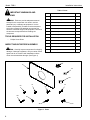
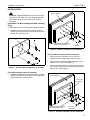
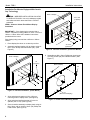
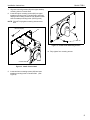
INSTALLATION INSTRUCTIONS
Display Interface
Model: FSB-V
BEFORE YOU BEGIN
CAUTION: To prevent damage that could affect or void the Factory warranty, and to the equipment that will be
attached to it, thoroughly study all instructions and illustrations before you begin the installation.
•
If you have any questions about this installation, contact Chief Manufacturing.
Chief® is a registered trademark of Milestone AV Technologies. All rights reserved.
Milestone AV Technologies, and its affiliated corporations and subsidiaries (collectively, "Milestone"), intend to make this manual accurate and complete. However, Milestone
makes no claim that the information contained herein covers all details, conditions or variations, nor does it provide for every possible contingency in connection with the
installation or use of this product. The information contained in this document is subject to change without notice or obligation of any kind. Milestone makes no representation
of warranty, expressed or implied, regarding the information contained herein. Milestone assumes no responsibility for accuracy, completeness or sufficiency of the information contained in this document.
8804-000293 RevB
Chief Manufacturing, a products division
2009 Milestone AV Technologies,
of Milestone AV Technologies
a Duchossois Group Company
8401 Eagle Creek Parkway, Savage, MN 55378
www.chiefmfg.com
• P: 800.582.6480 / 952.894.6280 • F:877.894.6918 / 952.894.6918
10/09
Model: FSB-V
Installation Instructions
Table 1: Parts
IMPORTANT WARNINGS AND
CAUTIONS!
ITEM
WARNING: Failure to provide adequate structural
strength for this component can result in serious
personal injury or damage to equipment! It is the
installer’s responsibility to make sure the structure to
which this component is attached can support five
times the combined weight of all equipment. Reinforce
the structure as required before installing the
component.
TOOLS REQUIRED FOR INSTALLATION
•
DESCRIPTION
QTY
10
BRACKET, Interface, 100 x 200
1
20
BUTTON, Mounting
4
30
SCREW, Phillips Flat Head, M4 x 12mm
6
40
SCREW, Phillips Flat Head, M4 x 20mm
6
50
SCREW, Phillips Flat Head, M4 x 25mm
6
60
SCREW, Phillips Pan Head, M4 x 10mm
4
70
SCREW, Phillips Pan Head, M4 x 12mm
4
80
SCREW, Phillips Pan Head, M4 x 20mm
4
90
SCREW, Phillips Pan Head, M4 x 25mm
4
100
SCREW, Phillips Pan Head, M4 x 30mm
4
110
SPACER, 3/4" x 1/4"
6
120
SPACER, Nylon 3/4" x 1/2"
6
Phillips Screw Driver
INSPECT MOUNT BEFORE ASSEMBLY
CAUTION: Carefully inspect components for shipping
damage. If damage is apparent, call your carrier claims
agent and do not continue with installation until the
carrier has reviewed the damage. (See Figure 1)
20
10
110
120
70
60
100
80
30
40
Figure 1: Parts
2
90
50
Installation Instructions
Model: FSB-V
INSTALLATION
Back of Display
CAUTION: IMPROPER INSTALLATION CAN LEAD
TO DISPLAY FALLING! Use only hardware provided
and referenced within these instructions. DO NOT
substitute!
Installation For Mounts Equipped With Latching
Flags
To install the FSB-V on Latching Flag Equipped Mounts:
1. Assemble four mounting buttons (20) to interface
bracket (10) using four M4 x 12mm Phillips pan head
screws (70). (See Figure 2)
10
20
Interface Bracket Assembly
(with mounting buttons)
30
(6 places)
Figure 3: Interface Installation, (Flush Mount)
Recessed Mount Display Interface Installation
1. Align and place six spacers (110 or 120) over
mounting holes in display back. (See Figure 4)
70
Figure 2: Assemble Mounting Buttons to Interface
2. Align and place interface bracket assembly over six
spacers (110 or 120). (See Figure 4)
3. Secure interface assembly to display back using six
M4 x 20mm (40) or six M4 x 25mm (50) Phillips flat
head screws. (See Figure 4)
Flush Mount Display Interface Installation
1. Assemble interface bracket assembly (with mounting
buttons) to display using six M4 x 12mm Phillips flat
head screws (30). (See Figure 3)
Back of Display
110 or 120
(6 places)
Interface Bracket Assembly
(with mounting buttons)
40 or 50
(6 places)
Figure 4: Interface Installation (Recessed Mount)
3
Model: FSB-V
Installation Instructions
Installation For Mounts Equipped With Centris
Cup Technology
Back of Display
CAUTION: IMPROPER INSTALLATION CAN LEAD
TO DISPLAY FALLING! Use only hardware provided
and referenced within these instructions. DO NOT
substitute!
110 or 120
(6 places)
VESA® 200mm x 100mm Flush Mount Display
Installation
IMPORTANT ! : If the display being mounted has a
VESA® compliant mounting pattern of 75mm x 75mm or
100mm x 100mm follow the installation instructions
provided with the mount.
If the display being mounted has a 200mm x 100mm
VESA® :
1. Place display face down on a clean dry surface
2. Assemble interface bracket (10) to display using six
M4 x 12mm Phillips flat head screws (30). (See
Figure 5)
10
40 or 50
(6 places)
Figure 6: Interface Installation, (Recessed Mount)
6. Assemble two M4 x 20mm Phillips pan head upper
mounting screws (80) into interface bracket. (See
Figure 7)
Back of Display
30
(6 places)
Back of Display
80
10
Figure 5: Interface Installation, (Flush Mount)
10
(Mounted on Display)
3. Align and place six spacers (110 or 120) over
mounting holes in display back. (See Figure 6)
4. Align and place interface bracket (10) over six
spacers (110 or 120). (See Figure 6)
5. Secure interface assembly to display back using six
M4 x 20mm (40) or six M4 x 25mm (50) Phillips flat
head screws. (See Figure 6)
4
Figure 7: Install Centris Mounting Screws
Installation Instructions
Model: FSB-V
7. Align two mounting screws (80) with upper teardrop
mounting holes in Centris head.
8. Insert two upper mounting screws (80) into upper
teardrop mounting holes in Centris head, and lower
display until mounting screws are fully seated in lower
area of teardrop mounting holes. (See Figure 8)
NOTE: DO NOT fully tighten mounting screws at this
time.
Back of Display
80
80
Figure 9: Install Lower Mounting Screws
10. Fully tighten four mounting screws.
Centris Head
Figure 8: Install Centris Head
9. Insert two lower mounting screws (80) into lower
teardrop mounting holes in Centris head. (See
Figure 9)
5
Model: FSB-V
6
Installation Instructions
Installation Instructions
Model: FSB-V
7
Model: FSB-V
8
Installation Instructions