1
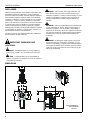
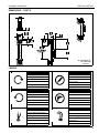
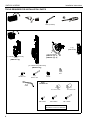
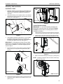
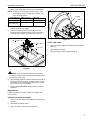
INSTALLATION INSTRUCTIONS
Instrucciones de instalación
Installationsanleitung
Instruções de Instalação
Istruzioni di installazione
Installatie-instructies
Instructions d´installation
KWP230
KWP130
Single and Dual Array Vertical Wall Mount
Spanish Product Description
German Product Description
Portuguese Product Description
Italian Product Description
Dutch Product Description
French Product Description
KWP130 / KWP230
KWP130 / KWP230
Installation Instructions
DISCLAIMER
Milestone AV Technologies and its affiliated corporations and
subsidiaries (collectively, "Milestone"), intend to make this
manual accurate and complete. However, Milestone makes no
claim that the information contained herein covers all details,
conditions or variations, nor does it provide for every possible
contingency in connection with the installation or use of this
product. The information contained in this document is subject
to change without notice or obligation of any kind. Milestone
makes no representation of warranty, expressed or implied,
regarding the information contained herein. Milestone assumes
no responsibility for accuracy, completeness or sufficiency of
the information contained in this document.
Chief® and Centris™ are registered trademarks of Milestone
AV Technologies. All rights reserved.
WARNING: Failure to read, thoroughly understand, and
follow all instructions can result in serious personal injury,
damage to equipment, or voiding of factory warranty! It is the
installer’s responsibility to make sure all components are
properly assembled and installed using the instructions
provided.
WARNING: Failure to provide adequate structural strength
for this component can result in serious personal injury or
damage to equipment! It is the installer’s responsibility to
make sure the structure to which this component is attached
can support five times the combined weight of all equipment.
Reinforce the structure as required before installing the
component.
WARNING: Exceeding the weight capacity can result in
IMPORTANT WARNINGS AND
CAUTIONS!
serious personal injury or damage to equipment! It is the
installer’s responsibility to make sure the combined weight of
all components attached to this accessory does not exceed
40 lbs (18.14 kg) for the KWP130, and 16.5 lbs (7.5 kg) per
display for the KWP230.
WARNING: A WARNING alerts you to the possibility of
serious injury or death if you do not follow the instructions.
CAUTION: A CAUTION alerts you to the possibility of
damage or destruction of equipment if you do not follow the
corresponding instructions.
DIMENSIONS
61
2.40
KWP130
116
4.55
100
3.94
142
5.60
75
2.95
115
4.53
75
2.95
100
3.94
122
4.80
VERTICAL
ADJUSTMENT
71
33 2.81
1.30
215
8.47
MEASUREMENTS:
[MILLIMETERS]
INCHES
2
Installation Instructions
KWP130 / KWP230
DIMENSIONS -- CONT’D
KWP230
MEASUREMENTS:
[MILLIMETERS]
INCHES
LEGEND
Tighten Fastener
Pencil Mark
Apretar elemento de fijación
Marcar con lápiz
Befestigungsteil festziehen
Stiftmarkierung
Apertar fixador
Marcar com lápis
Serrare il fissaggio
Segno a matita
Bevestiging vastdraaien
Potloodmerkteken
Serrez les fixations
Marquage au crayon
Loosen Fastener
Drill Hole
Aflojar elemento de fijación
Perforar
Befestigungsteil lösen
Bohrloch
Desapertar fixador
Fazer furo
Allentare il fissaggio
Praticare un foro
Bevestiging losdraaien
Gat boren
Desserrez les fixations
Percez un trou
Phillips Screwdriver
Hex-Head Wrench
Destornillador Phillips
Llave de cabeza hexagonal
Kreuzschlitzschraubendreher
Sechskantschlüssel
Chave de fendas Phillips
Chave de cabeça sextavada
Cacciavite a stella
Chiave esagonale
Kruiskopschroevendraaier
Zeskantsleutel
Tournevis à pointe cruciforme
Clé à tête hexagonale
3
KWP130 / KWP230
Installation Instructions
TOOLS REQUIRED FOR INSTALLATION / PARTS
#2
1/8"
5/32" (included)
C (1)
[Wall bracket]
B
[Centris bracket]
[KWP130 - qty. 1]
[KWP230 - qty. 2]
[7" Vertical array wall mount]
A1 (1)
[KWP130 only]
A2 (1)
[17" Vertical array wall mount]
[KWP230 only]
G (2)
#10
D (2)
1/4-20 x 1/2"
H (1)
5/32"
F (2)
1/4-20"
E (2)
#10 x 2-1/2"
Array
Hardware Kit
K
.5 x .194 x .75"
J
.5 x .194 x .375"
L
M4 x12mm
M
M4 x 20mm
N
M4 x 30mm
Quantities of 4 each for KWP130.
Quantities of 8 each for KWP230.
4
Installation Instructions
KWP130 / KWP230
Assembly And Installation
Installation to Wall
(C)
1.
Determine location for mount keeping in mind display size,
extension, height adjustment (if applicable), and pitch/roll
requirements. Wall bracket (C) MUST be installed into
wood stud.
2.
Using wall bracket (C) as a template, drill two 1/8" diameter
pilot holes through top and bottom holes of bracket and into
wall structure. (See Figure 1)
(G) x 2
3
Set Screw
(C)
Figure 3
(E) x 2
Centris Bracket to Array
IMPORTANT ! : If you will be installing a display with
RECESSED mounting holes, then proceed to Display
Installation section before continuing with this mount
installation procedure.
2
Figure 1
3.
1.
Install 1/4-20" square nut (F) into back groove of array (A1
or A2) and line up with bottom hole on plate. (See Figure 4)
2.
Install 1/4-20 x 1/2" button head cap screw (D) into lower
hole on array mount (A1 or A2) and through square nut (F).
Using Phillips screwdriver, install two #10 x 2-1/2" Phillips
pan tapping screws (E) through two #10 washers (G),
bracket (C), and drywall into wood stud. Ensure bracket (C)
is vertical, then tighten screws (E). (See Figure 1)
IMPORTANT ! : Overtightening screws (E) may cause
bracket (C) to compress into soft wall surface, resulting in
difficult mount installation or improper engaging of set
screw in Step 5.
4.
2
Insert top of mount (A1 or A2) over lip on top of bracket (C).
Swing mount (A1 or A2) down flush against wall. (See
Figure 2)
(D)
(F)
1
(KWP130 shown)
(A1 or A2)
Figure 4
(C)
3.
Slide one Centris bracket (B) over array (A1). (See Figure 5)
NOTE: If installing a KWP230, slide two Centris brackets (B)
onto the array (A2).
3
(KWP130 shown)
(KWP130 shown)
Figure 2
5.
Tighten set screw using 5/32" hex key (H). Ensure set screw
engages back side of bracket (C) to properly secure mount.
(See Figure 3)
Figure 5
5
KWP130 / KWP230
4.
Installation Instructions
Adjust Centris bracket (B) to desired height and tighten the
knob closest to the array (A1) to secure Centris bracket to
array. (See Figure 6)
WARNING: Exceeding the weight capacity can result in
serious personal injury or damage to equipment! It is the
installer’s responsibility to make sure the combined weight of
all components attached to this accessory does not exceed
40 lbs (18.14 kg) for the KWP130, and 16.5 lbs (7.5 kg) per
display for the KWP230.
NOTE: If installing a KWP230, adjust two Centris brackets (B)
to desired height following instructions in Step 4.
Height adjustment
knob
FLUSH MOUNTING HOLES
CAUTION: Using screws of improper size may damage
your display! Proper screws will easily and completely thread
into display mounting holes.
CAUTION: Inadequate thread engagement in display may
cause display to fall! Back out screws ONLY as necessary to
allow installation of Centris bracket!
Figure 6
5.
6.
Install 1/4-20" square nut (F) into the top of the back groove
of array (A1 or A2) and line up with top hole on plate. (See
Figure 7)
1.
Ensure Centris bracket is able to swivel and tilt easily, yet
still be tight enough to hold display in desired position.
Adjust as required before proceeding. See Adjustments
section for detail.
2.
Using Phillips screwdriver, carefully install two M4 x 12mm
Phillips pan machine screws (L) into the upper mounting
holes on the display. Thread screws completely into
display, then back out 3 complete turns.
3.
Pick up and align display so that screws (L) (installed on the
back of the display in the previous step) fit into the mounting
holes on the Centris bracket; rotate the bracket as required.
Lower the display firmly into place. (See Figure 8)
Install 1/4-20 x 1/2" button head cap screw (D) into upper
hole on array and through square nut (F). (See Figure 7)
(F)
6
5
(D)
(L) x 2
(A1 or A2)
(B)
Figure 8
(KWP130 shown)
4.
Using Phillips screwdriver, install two remaining M4 x 12mm
Phillips pan machine screws (L) through the lower mounting
holes in Centris bracket into the display.
Display Installation
5.
Tighten all four screws (L). Do not overtighten!
The mounting holes on the back of your display will either be
flush with the back surface, or recessed into the back surface.
Refer to the applicable installation procedure.
RECESSED MOUNTING HOLES
Figure 7
6
1.
Carefully place display face down on protective surface.
2.
Determine depth of recessed mounting holes relative to
back surface of display (against which Centris head will
contact).
Installation Instructions
3.
KWP130 / KWP230
Select proper length spacer and screw from table below:
NOTE: All spacers used should be the same length. If the
recess depths result in multiple spacer lengths, then
select the longer spacer.
IF recess DEPTH is: THEN use spacer:
AND screw:
3/8" or less
J (3/8" long)
M (M4 x 20mm)
More than 3/8" up to
and including 3/4"
K (3/4" long)
N (M4 x 30mm)
4.
Place the four selected spacers over each of the mount
holes on the back of the display.
5.
Pick up and orient the Centris bracket (B) so that the
mounting holes are aligned with the holes in the spacers;
rotate the Centris bracket as required. (See Figure 9)
Knob B
Knob A
Figure 10
(B)
(M or N) x 4
PITCH / YAW / ROLL
1.
Using your fingers, slightly loosen adjustment knob B. (See
Figure 10)
2.
Adjust display as desired.
3.
Using your fingers, tighten adjustment knob B.
(J or K) x 4
Figure 9
CAUTION: Using screws of improper size may damage
your display! Proper screws will easily and completely thread
into display mounting holes.
6.
Using Phillips screwdriver, install four selected screws (M or
N) through the mounting holes in Centris bracket, through
the spacers (J or K), into the display. (See Figure 9) Tighten
all four screws. Do not overtighten!
7.
Return to Centris Bracket to Array section to complete
installation.
Adjustments
If previously attached, disconnect cables from display, then
remove display.
VERTICAL POSITION ON ARRAY
1.
Using your fingers, slightly loosen adjustment knob A. (See
Figure 10)
2.
Slide display to desired position.
3.
Using your fingers, tighten adjustment knob A.
7
KWP130 / KWP230
Installation Instructions
USA/International
Europe
Chief Manufacturing, a products division
of Milestone AV Technologies
8832-002011 Rev01
2009 Milestone AV Technologies, a
Duchossois Group Company
www.chiefmfg.com
07/09
Asia Pacific
A
P
F
A
P
F
A
8401 Eagle Creek Parkway, Savage, MN 55378
800.582.6480 / 952.894.6280
877.894.6918 / 952.894.6918
Fellenoord 130 5611 ZB EINDHOVEN, The Netherlands
+31 (0)40 2668620
+31 (0)40 2668615
Room 24F, Block D, Lily YinDu International Building
LuoGang, BuJi Town, Shenzhen, CHINA.
P +86-755-8996 9226
F +86-755-8996 9217