1
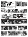
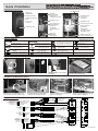
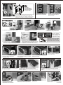
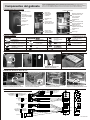
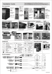
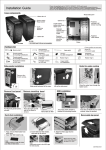
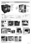
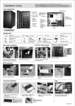
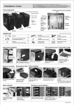
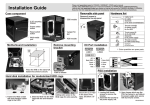
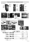
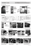
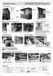
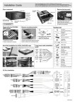
Multi-media port
Side panel latch
and lock
3-speed fan
controller
Patented tool-less
5.25” device
mounting kit
5.25” bezels
140mm fan
5.25" to 3.5"
convertor
140mm fans with
air filter
Liquid-cooling
system tube vents
with rubber cover
Patented Tool-less
PCI add-on card
holder
140mm fans
140mm fan with
air filter
Power mounting
bracket
HDD cage
Hardware list
(2)
Thumb screw(6)
for mount
Thumb screw(26)
for HDD mounting
SATA cable(2)
for HDD
Rubber ring(10)
for HDD mounting
Thumb screw(3)
for mount
Screw (10)
for 2.5” HDD
PCI card holder-S(1)
PCI card holder-L(6)
Box(1)
for spare parts
(4)
for fix CD-ROM
Rubber(4)
for 5.25" ODD bezel
1
for cable management
Thumb screw(2)
Stand off (9)
(5)
for power supply mounting
Hex wrench for M/B(1)
stand-off
Thumb screw(7)
for PCI card holder
2.5" Hard disk installation
Side panels installation
Loose the screw and pull the
latch to release the side panel.
Remove the side panel.
Adding a lock to secure the
hardware.
2.5" HDD mounted to the anti-vibration
HDD cage.
3.5" Hard disk installation
Loose thumb screws to remove the
HDD cage.
Insert HDD, secured with thumb
screws.
I/O port installation
KEY 10
Black(GND) 8
Green 6
White 4
Red 2
9
7 Black(GND)
5 Green
3 White
1 Red
KEY10
Black(GND) 8
Green 6
White 4
Red 2
9
7 Black(GND)
5 Green
3 White
1 Red
1
3
5
7
9
2 Red(MIC)
4 Brown(MIC-PWE)
6 Yellow(R-OUT)
8
10 Blue(L-OUT)
EAR
MIC
USB
Green(SENSE2 RETUR)
KEY
Orange(SENSE1 RETUR)
Black(PRESENCE)
Black(GND)
Black(AGND)
NC
Yellow(R-RET)
KEY
Blue(L-RET)
Fasten the thumb screw to secure
the HDD cage.
USB
USB
9
7
5
3
1
HD AUDIO
AC'97
Blue(PORT2 L) 10
Black(SENSE SEND) 8
Yellow(PORT2 R) 6
Brown(PORT1 R) 4
Red(PORT1 L) 2
Insert the HDD cage to the mounting
position.
USB
9
7
5
3
1
Black(GND)
White(+12V)
Red(TPB-)
Black(VG)
Orange(TPA-)
1394
IEEE1394
Black(KEY) 10
White(+12V) 8
Green(TPB+) 6
Black(VG) 4
Blue(TPA+) 2
E-SATA
Connector
SATA
C50.X10000.00E-1
PCI Add-on card installation
!
!
!
Note: For area where hard
to reach use the
long thumb screw
Open the aluminum latch to
remove the PCI slot bracket.
Loose the thumb screws to
release the M/B tray.
1
2
Secure the stand-off on the M/B tray which match
with the M/B fix points, place the M/B on the stand-off
fasten with the thumb screws to secure.
Push the card into the PCI slot,
close the aluminum latch to
secure the card.
ODD installation
1. Remove the 5.25" to 3.5" converter.
2. Remove the 5.25" ODD
bezel.
3. Slide the 5.25" ODD bezel
downwards to remove it.
If you wish to use the
5.25" ODD bezel,
please adjust the metal
pin position on the
mounting bracket
Adding the rubber pad to ODD's
eject bottom, when 5.25" ODD
bezel couldn't reach to the ODD.
5. Push the CD-ROM into the ODD cage
module, close the bracket to secure.
6. Reverse previous steps for installation
bezel & converter.
4. By pressing plastic
handle to release the
mounting bracket.
PSU tray installation
Remove the HDD cage for long
PSU.
Loosing four thumb screws to remove Assembling the power supply with
PSU mounting bracket, and push
the PSU mounting bracket.
in gently.
Fasten four thumb screws to the case
to secure.
Removable upper double fan module
Removable fan module
Loosing four screws to remove fan
module.
Loosing two screws to remove fan module,
and it also equipped with washable air filer.
Follow the arrow to remove the filter, press the
plastic clips to release the washable air filter.
VGA card pillar installation guide
1
2
Insert the PCI add-on card holder into Press the end of the rolder, and push
slot on the pillar.
it into the slot.
3
Insert the screw.
4
Tighten the screw to push in the
holder to against the card.
C50.X10000.00E-2
Guide d'installation
Composants du boîtier:
Port Multi-média
Bouton de
réinitialisation
Bouton de courant
Verrou du
panneau latéral
Contrôleur du
ventilateur 3 vitesses
Support de montage
5,25”
Patented tool-less
5.25” device
mounting kit
Ventilateur 14cm
5.25" to 3.5"
convertor
Ventilateur 14cm
Trous pré-percés
pour le passage
du tube du
système de
refroidissement à
eau
Ventilateur 14cm
Colonne de carte VGA
Support de carte
PCI breveté
additionnel à
montage sans outil
Ventilateur 14cm
Support de
fixation de
l'alimentation
Module breveté du
lecteur de disque dur
Liste du matériel
Avertisseur (1)
Câble SATA (2)
pour le lecteur de disque dur
Rondelle en caoutchouc (10)
pour lecteur de disque dur
Boîte (1) pour les
pièces de rechange
Porte-carte PCI S (1)
Porte-carte PCI L (6)
Pince (1) pour gestion du
câblage
Vis à serrage à mains
(2) de rechange
Tournevis (1) pour installer
la carte mère
Vis (5) pour fixer le
bloc d'alimentation
Screw (10)
for 2.5” HDD
Rubber(4)
for 5.25" ODD bezel
Vis (4) pour fixer le lecteur
et la carte mère
Boulon de fixation (9)
pour la carte mère
Vis à serrage à mains (7)
pour le porte-carte du PCI
Installation de disque dur de 2,5"
Installation des panneaux latéraux
Défaites la vis et poussez le loquet
pour libérer le panneau latéral.
Vis de fixation (26) du
lecteur de disque dur
Vis à serrage à main (6) pour
l'installation de la carte mère
Vis à serrage à main (3) pour
l'installation de la carte mère
Collier de serrage (2)
Déposez le panneau latéral.
Ajout d'un verrou pour sécuriser
le matériel.
Disque dur de 2,5" monté dans le boîtier
de disque dur antivibrations.
Installation de disque dur de 3,5"
Desserrez les vis à serrage à main
pour enlever le boîtier du disque dur.
Insérez le disque dur, et fixez-le à
l'aide des vis à serrage à main.
I/O port installation
KEY 10
Black(GND) 8
Green 6
White 4
Red 2
9
7 Black(GND)
5 Green
3 White
1 Red
KEY10
Black(GND) 8
Green 6
White 4
Red 2
9
7 Black(GND)
5 Green
3 White
1 Red
1
3
5
7
9
2 Red(MIC)
4 Brown(MIC-PWE)
6 Yellow(R-OUT)
8
10 Blue(L-OUT)
EAR
MIC
USB
Green(SENSE2 RETUR)
KEY
Orange(SENSE1 RETUR)
Black(PRESENCE)
Black(GND)
Black(AGND)
NC
Yellow(R-RET)
KEY
Blue(L-RET)
Serrez la vis à serrage à main pour
fixer le boîtier à disque dur.
USB
USB
9
7
5
3
1
HD AUDIO
AC'97
Blue(PORT2 L) 10
Black(SENSE SEND) 8
Yellow(PORT2 R) 6
Brown(PORT1 R) 4
Red(PORT1 L) 2
Insérez le boîtier du disque dans sa
position de montage.
USB
9
7
5
3
1
Black(GND)
White(+12V)
Red(TPB-)
Black(VG)
Orange(TPA-)
1394
IEEE1394
Black(KEY) 10
White(+12V) 8
Green(TPB+) 6
Black(VG) 4
Blue(TPA+) 2
E-SATA
Connector
SATA
C50.X1000.00E-1
Installation de la carte mère
PCI Add-on card installation
!
!
Remarque :
pour la zone dont
l'accès est difficile,
utilisez la longue vis
à serrage à main
!
Loose the thumb screws to
release the M/B tray.
1
2
Fixez l'écartement du tiroir de la carte mère qui
correspond au point de fixation de la carte mère.
Placez la carte mère sur la fixation d'écartement en
utilisant les vis à main pour maintenir l'ensemble.
Open the aluminum latch to
remove the PCI slot bracket.
Push the card into the PCI slot,
close the aluminum latch to
secure the card.
Installation de l'ODD
1. Enlevez le convertisseur 5,25" en 3,5".
2. Retirez la lunette 5,25 pouces
de l'ODD.
3. Faites glisser la lunette 5,25" de
l'ODD vers le bas pour la retirer.
Si vous utilisez la lunette
ODD 5,25", veuillez
ajuster la position de la
goupille métallique sur
le support de montage
Adding the rubber pad to ODD's
eject bottom, when 5.25" ODD
bezel couldn't reach to the ODD.
5. Poussez le lecteur de CD-ROM dans le
module ODD et fermez le support pour fixer.
6. Inversez la procédure précédente pout
l'installation de la lunette et du convertisseur.
4. En appuyant sur la
poignée en plastique
pour libérer le support de montage.
Installation du plateau du PSU
Enlevez le boîtier du disque dur
pour un PSU long.
Desserrez les quatre vis à serrage à
main pour retirer le plateau de
montage du PSU.
Assemblez le bloc d'alimentation
avec le plateau du PSU, et enfoncez
-le doucement.
Serrez les quatre vis à main sur le
boîtier pour le fixer.
Module double ventilateur supérieur amovible
Module ventilateur amovible
En desserrant les quatre vis pour enlever
le module ventilateur.
En dévissant deux vis pour enlever le module
ventilateur, et il est également équipé d'un filtre à air
lavable.
Suivez la flèche étroite pour enlever le filtre,
appuyez sur les clips en plastique pour enlever le
filtre à air lavable.
Guide d'installation de la colonne de la carte VGA
1
Insérez le support de carte
supplémentaire PCI dans
l'emplacement sur la colonne.
2
Appuyez sur l'extrémité du support,
et enfoncez-le dans l'emplacement.
3
Insérez la vis.
4
Serrez la vis pour enfoncer le support
contre la carte.
C50.X1000.00E-2
Installationsanleitung
Gehäusekomponenten
Mit Gummi umrandete
Öffnungen für die
Leitungen eines
Flüssigkühlsystems
Rückstellschalter
Netzschalter
Multimedia-Anschluss
Patentiertes
werkzeugfreies
5,25"Laufwerkbefestigungsteil
Lüfterdrehzahlregler
(3 Stufen)
5.25” bezels
5,25Laufwerkfachblende
140mm-Lüfter
140mm-Lüfter
Vorgebohrte
Löcher für
Wasserkühlsystemschläuche
VGA-Kartenstütze
Patentierter
werkzeugfreier
PCI-Kartenhalter
140mm-Lüfter
140mm-Lüfter
Herausnehmbare
Netzteilhalterung
Festplattenfach
Hardware list
Summer-Kabel (1 Stück)
Kabelbinder (2 Stück)
Câble SATA (2) pour le
lecteur de disque dur
Gummiring (10 Stück)
PCI-Kartenhalter klein (1 Stück)
PCI-Kartenhalter groß (6 Stück)
Ersatzteilbox (1 Stück)
Rändelschraube für die Befestigung
der Hauptplatine (6 Stück)
Rändelschraube für die Befestigung
der Hauptplatine (3 Stück)
Schraube (10) zur
Befestigung der HDD
Rubber(4)
for 5.25" ODD bezel
Schraube (4 Stück)
Klammer für die Kabelanordnung
(1 Stück)
Rändelschraube für die
Festplattenhalterung (2 Stück)
Inbusschlüssel für
Hauptplatinenabstandhalter
Schraube zum Befestigen
des Netzteils (5 Stück)
Abstandhalter für die Hauptplatine
(9 Stück)
Rändelschraube für PCIKartenhalter (7 Stück)
Installation der seitlichen Abdeckplatten
Lockern Sie die Schraube und
ziehen die Klinke, um die seitliche
Abdeckplatte auszuklinken.
Rändelschraube (26 Stück)
2,5"-Festplatteninstallation
Sie können zusätzlich ein Schloss
verwenden, um die Hardware zu
sichern.
Entfernen Sie die seitliche
Abdeckplatte.
2,5"-Festplatte in der schwingungsfreien
Festplattenhalterung befestigt.
3,5"-Festplatteninstallation
Lösen Sie die Rändelschrauben, um
die Festplattenhalterung zu entfernen.
Legen Sie die Festplatten ein und
sichern sie mit Rändelschrauben.
Grün (SENSE2 RETUR)
SCHLÜSSEL
Orange (SENSE1 RETUR)
Schwarz (PRESENCE)
Schwarz (ERDE)
SCHLÜSSEL
Schwarz (ERDE)
Grün
Weiß
Rot
10
8
6
4
2
9
7 Schwarz (ERDE)
5 Grün
3 Weiß
1 Rot
SCHLÜSSEL 10
Schwarz (ERDE) 8
Grün 6
Weiß 4
Rot 2
9
7 Schwarz(ERDE)
5 Grün
3 Weiß
1 Rot
HD AUDIO
9
7
5
3
1
1
3
5
7
9
2 Rot (MIC)
4 Braun (MIC-PWE)
6 Gelb (R-OUT)
8
10 Blau (L-OUT)
EAR
MIC
USB
10
8
6
4
2
Schwarz (AGND)
NC
Gelb (R-RET)
SCHLÜSSEL
Blau (L-RET)
USB
USB
Blau (PORT2L)
Schwarz (SENSE SEND)
Gelb (PORT2 R)
Braun (PORT1 R)
Rot (PORT1 L)
AC'97
Installation des E/A-Anschlusses
Schieben Sie die Festplattenhalterung Ziehen Sie die Rändelschraube fest,
bis in die Befestigungsposition.
um die Festplattenhalterung zu
befestigen.
USB
10
8
6
4
2
9
7
5
3
1
Schwarz (ERDE)
Weiß(+12V)
Rot(TPB-)
Schwarz(VG)
Orange(TPA-)
1394
IEEE1394
Schwarz (KEY)
Weiß (+12 V)
Grün (TPB+)
Schwarz (VG)
Blau (TPA+)
E-SATA
Anschlussstecker
SATA-Kabel
C50.X1000.00E-1
PCI Add-on card installation
!
!
Note: For area where hard
to reach use the
long thumb screw
!
Open the aluminum latch to
remove the PCI slot bracket.
Loose the thumb screws to
release the M/B tray.
1
2
Secure the stand-off on the M/B tray which match
with the M/B fix points, place the M/B on the stand-off
fasten with the thumb screws to secure.
Push the card into the PCI slot,
close the aluminum latch to
secure the card.
Installation optischer Laufwerke
1. Entfernen Sie den 5,25"-auf-3,5"-Adapter
3. Schieben Sie die 5,25"-Blende nach
unten, um sie zu entfernen.
2. Entfernen Sie die 5,25"-Blende, die
für ein optisches Laufwerk vorgesehen ist.
Wenn Sie die für ein
optisches Laufwerk
vorgesehene 5,25"-Blende
verwenden möchten,
verstellen Sie bitte die
Position der Metallstifte
an dem Befestigungsteil.
Kleben Sie den Gummipuffer an
die Auswurftaste des optischen
Laufwerks, falls die 5,25"-Blende
an dem Laufwerkfach das
installierte optischen Laufwerk nicht
berühren kann.
5. Schieben Sie das optische Laufwerk in das
entsprechende Fach ein und schließen das
Befestigungsteil.
6. Führen Sie die vorigen Schritte in umgekehrter
Reihenfolge aus, um die Blende und den
Adapter anzubringen.
4. Drücken Sie die
Kunststoffklinke und
machen das Befestigungsteil auf.
Netzteilinstallation
Drehen Sie die vier Rändelschrauben Bauen Sie das Netzteil und die
Verwenden Sie vier Rändelschrauben,
Halterung zusammen und schieben
heraus, um die Netzteilhalterung
um das Netzteil zu befestigen.
die Einheit anschließend vorsichtig ein.
herauszunehmen.
Remove the HDD cage for long
PSU.
Abnehmbares oberes Dual-Lüftermodul
Removable fan module
Lockern Sie die vier Schrauben, um das
Lüftermodul abzunehmen.
Lockern Sie die zwei Schrauben, um das Lüftermodul
abzunehmen. Das Modul ist ebenfalls mit einem
waschbaren Luftfilter ausgestattet.
Drücken Sie die Kunststoffgriffe in Pfeilrichtung, um
den waschbaren Filter zu entfernen.
Installation der VGA-Kartenstütze
1
Stecken Sie den PCI-Kartenhalter
durch die Aussparung an der Stütze.
2
Drücken Sie das Ende des Halters
weiter durch die Aussparung.
3
Stecken Sie die Schraube ein.
4
Ziehen Sie die Schraube fest, um
den Halter gegen die Karte zu drücken.
C50.X1000.00E-2
Please visit www.lian-li.com for FRANCE / GERMANY / SPAIN user's manual
Veuillez visiter www.lian-li.com pour le manuel d’installation en FRANÇAIS/ALLEMAND/ESPAGNOL.
Visite el sitio Web www.lian-li.com para obtener el manual del usuario en FRANCÉS ALEMÁN Y ESPAÑOL
Besuchen Sie bitte www.lian-li.com für die französische/ deutsche/ spanische Gebrauchsanleitung
Componentes del gabinete
Componentes de la carcasa:
Puerto multimedia
Botón de reinicio
Cierre del
panel lateral
3-speed fan
controller
Botón de
encendido/apagado
Soporte de montaje
de 5,25”
Montaje patentado de
dispositivos de 5,25”
que no requiere
herramientas
Ventilador de
14cm
5.25" to 3.5"
convertor
Ventilador de
14cm
Pilar para tarjeta VGA
Liquid-cooling
system tube vents
with rubber cover
Ventilador de
14cm
Soporte patentado de
tarjetas PCI de
expansión que no
requiere herramientas
Ventilador de
14cm
HDD cage
Soporte para
sujetar la fuente
de alimentación
Lista de hardware
(2)
Zumbador (1)
Thumb screw(6)
for mount
Thumb screw(26)
for HDD mounting
Cable SATA (1)
para disco duro
Sujeción de tarjeta PCI-S(1)
Sujeción de tarjeta PCI-L(6)
Rubber ring(10)
for HDD mounting
Thumb screw(3)
for mount
Screw (10)
for 2.5” HDD
Box(1)
for spare parts
(4)
for fix CD-ROM
Rubber(4)
for 5.25" ODD bezel
1
for cable management
Thumb screw(2)
Stand off (9)
(5)
for power supply mounting
Hex wrench(1)
for M/B copper bolt
Thumb screw(7)
for PCI card holder
Instalación del disco duro de 2,5"
Instalación de los paneles laterales
Afloje el tornillo y tire del seguro
para liberar el panel lateral.
Extraiga el panel lateral.
Agregue un candado para
asegurar el hardware.
Disco duro de 2,5" colocado en la cubierta
para discos duros con antivibración.
Instalación del disco duro de 3,5"
Afloje los tornillos mariposa para
extraer la cubierta para discos duros.
Inserte el disco duro y asegúrelo
con los tornillos mariposa.
Verde (SENSE2 RETUR)
BOTÓN
Naranja (SENSE1 RETUR)
Negro (PRESENCE)
Negro (TIERRA)
BOTÓN
Negro (GND)
Verde
Blanco
Rojo
10
8
6
4
2
9
7 Negro (GND)
5 Verde
3 Blanco
1 Rojo
BOTÓN10
Negro (GND) 8
Verde 6
Blanco 4
Rojo 2
9
7 Negro (GND)
5 Verde
Blanco
3 Rojo
1
HD AUDIO
9
7
5
3
1
2 Rojo (MIC)
4 Marrón (MIC-PWE)
6 Amarillo (R-OUT)
8
10 Azul (L-OUT)
AUR
MIC
USB
10
8
6
4
2
Negro (AGND) 1
S/Color 3
Amarillo (R-RET) 5
BOTÓN 7
Azul (L-RET) 9
Apriete el tornillo mariposa para
asegurar la cubierta para discos duros.
USB
USB
Azul (PORT2 LI)
Negro (SENSE SEND)
Amarillo (PORT2 R)
Marrón (PORT1 R)
Rojo (PORT1 R)
AC'97
Instalación de Puerto de Entrada/Salida
Inserte la cubierta para discos duros
en la posición de montaje.
USB
9
7
5
3
1
Negro (GND)
Blanco (+12V)
Rojo (TPB-)
Negro (VG)
Naranja (TPA-)
1394
IEEE1394
Negro (KEY) 10
Blanco (+12V) 8
Verde (TPB+) 6
Negro (VG) 4
Azul (TPA+) 2
Conector
E-SATA
Cable SATA
C50.X10000.00E-1
PCI Add-on card installation
!
!
Note: For area where hard
to reach use the
long thumb screw
!
Open the aluminum latch to
remove the PCI slot bracket.
Loose the thumb screws to
release the M/B tray.
1
2
Secure the stand-off on the M/B tray which match
with the M/B fix points, place the M/B on the stand-off
fasten with the thumb screws to secure.
Push the card into the PCI slot,
close the aluminum latch to
secure the card.
Instalación de la unidad de discos ópticos
1. Extraiga el convertidor de 5,25" a 3,5".
2. Extraiga el marco de la unidad
de discos ópticos de 5,25”.
3. Deslice el marco de la unidad de
discos ópticos de 5,25" para extraerlo.
Si desea utilizar el marco
de las unidades de discos
ópticos de 5,25", ajuste la
posición de la clavija de
metal ubicada en el soporte
de montaje.
Coloque una almohadilla de goma
en el botón de expulsión de la unidad
de discos ópticos cuando el marco de
la unidad de discos ópticos de 5,25"
no llega a la unidad de discos ópticos.
5. Empuje la unidad de CD-ROM hacia el
módulo de discos ópticos y cierre el
soporte para asegurar.
6. Realice los pasos anteriores a la inversa
para la instalación del marco y convertidor.
4. Presione la perilla de
plástico para liberar el
soporte de montaje.
PSU tray installation
Afloje los cuatro tornillos mariposa
para extraer el soporte de montaje
de la fuente de alimentación.
Ensamble la fuente de alimentación
Apriete los cuatro tornillos mariposa
con el soporte de montaje de la fuente en el gabinete para asegurar la fuente
de alimentación y empújela sutilmente de alimentación.
hacia adentro.
Módulo superior de dos ventiladores extraíble
Módulo de ventilador extraíble
Siga la flecha para extraer los filtros de aire y
presione los pestillos de plásticos para liberar los
filtros de aire lavables.
Afloje los cuatro tornillos para extraer el
módulo de ventiladores.
Extraiga la cubierta para discos
duros en el caso de fuentes de
alimentación largas.
Afloje los dos tornillos para extraer el módulo de
ventilador que posee filtro de aire lavable.
Guía de instalación del soporte para tarjetas VGA
1
Inserte el soporte de tarjetas PCI de
expansión en la ranura.
2
Haga presión sobre el extremo del
soporte y empújelo hacia la ranura.
3
Inserte el tornillo.
4
Apriete el tornillo para colocar el
soporte contra la tarjeta.
C50.X10000.00E-2