1
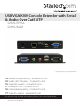
USB VGA KVM Console Extender with Serial
& Audio Over Cat5 UTP
SV565UTPUSA
SV565USAGB
*actual product may vary from photos
DE: Bedienungsanleitung - de.startech.com
FR: Guide de l'utilisateur - fr.startech.com
ES: Guía del usuario - es.startech.com
IT: Guida per l'uso - it.startech.com
NL: Gebruiksaanwijzing - nl.startech.com
PT: Guia do usuário - pt.startech.com
For the most up-to-date information, please visit: www.startech.com
Manual Revision: 03/02/2012
FCC Compliance Statement
This equipment has been tested and found to comply with the limits for a Class B digital
device, pursuant to part 15 of the FCC Rules. These limits are designed to provide reasonable
protection against harmful interference in a residential installation. This equipment generates,
uses and can radiate radio frequency energy and, if not installed and used in accordance with
the instructions, may cause harmful interference to radio communications. However, there
is no guarantee that interference will not occur in a particular installation. If this equipment
does cause harmful interference to radio or television reception, which can be determined by
turning the equipment off and on, the user is encouraged to try to correct the interference by
one or more of the following measures:
• Reorient or relocate the receiving antenna.
• Increase the separation between the equipment and receiver.
• Connect the equipment into an outlet on a circuit different from that to which the receiver
is connected.
• Consult the dealer or an experienced radio/TV technician for help.
Use of Trademarks, Registered Trademarks, and other Protected Names and Symbols
This manual may make reference to trademarks, registered trademarks, and other
protected names and/or symbols of third-party companies not related in any way to
StarTech.com. Where they occur these references are for illustrative purposes only and do not
represent an endorsement of a product or service by StarTech.com, or an endorsement of the
product(s) to which this manual applies by the third-party company in question. Regardless
of any direct acknowledgement elsewhere in the body of this document, StarTech.com hereby
acknowledges that all trademarks, registered trademarks, service marks, and other protected
names and/or symbols contained in this manual and related documents are the property of
their respective holders.
Instruction Manual
Table of Contents
Introduction.............................................................................................1
Packaging Contents.................................................................................................................................. 1
System Requirements............................................................................................................................... 1
Installation...............................................................................................2
Front View..................................................................................................................................................... 2
Rear View....................................................................................................................................................... 3
Hardware Installation............................................................................................................................... 4
Driver Installation....................................................................................................................................... 4
Configuration...........................................................................................5
Serial Data Link........................................................................................................................................... 5
Automatic Calibration Button and Light........................................................................................... 5
Manual Calibration and Settings Menu............................................................................................. 5
Commands................................................................................................................................................... 6
Transmitter Unit specific commands.................................................................................................. 6
Image Quality.............................................................................................................................................. 7
Firmware Upgrade..................................................................................................................................... 7
Troubleshooting......................................................................................8
Specifications...........................................................................................10
Technical Support...................................................................................11
Warranty Information.............................................................................11
Instruction Manual
i
Introduction
The SV565UTPUSA USB VGA KVM Console Extender w/ Serial & Audio over Cat5 UTP
(1000 ft) lets you control a server, workstation or multiple computers (connected
through a KVM Switch) over standard Cat5 or Cat6 UTP Ethernet cable, at distances of
up to 1000ft (333m) over a secure remote connection to a locked (secure) server.
Attached mounting brackets on the remote unit allow the console extender to
be mounted in a convenient location, and features support for resolutions up to
1920x1080, with automatic image calibrations for out-of-the-box performance and
manual controls accessible via the serial interface.
For added convenience, the Console/KVM extender supports USB computer
connections, and is compatible with any brand of USB KVM Switch.
Packaging Contents
• Transmitter unit
• Receiver unit
• USB A-B cable
• VGA extension cable (male/female)
• Power Adapter
• Instruction Manual
System Requirements
• VGA and USB enabled computer system/KVM switch
• Standard 104-key wired USB keyboard
• Standard 3-button wired USB mouse
• VGA enabled display device (i.e. monitor, projector, etc.) with VGA cable
• Available AC electrical outlet at Receiver Unit location
• OPTIONAL: Additional Receiver units for cascaded operation
Instruction Manual
1
Installation
Front View
1
2
3
4
5
Transmitter Unit
1. DE-15 VGA In (male)
2. 3.5mm mini-jack audio In
3. 3.5mm mini-jack microphone Out
4. USB type B host connector
5. DB9 RS-232 serial (female)
1
2
3
Receiver Unit
1. DE-15 VGA Out (female)
2. 3.5mm mini-jack audio Out
3. 3.5mm mini-jack microphone In
4. USB type A peripheral connectors
5. DB9 RS-232 serial (male)
Instruction Manual
2
4
5
Rear View
1
2
3
Transmitter Unit
1. DC Power connector
2. RJ45 Link connector
3. 3.5mm mini-jack Audio Out
4. DE-15 VGA Out (female)
1
2
3
4
Receiver Unit
1. DC Power connector
2. Setup button
3. RJ45 Link Out connector
4. RJ45 Link In connector
Instruction Manual
3
4
Hardware Installation
Transmitter Unit
1. Connect the included USB cable between the computer/KVM and the USB port on
the Transmitter Unit. This also provides power to the Transmitter Unit.
Optional: A 5V DC power adapter can be used for backup or if not using the USB
cable. This power adapter is not included.
2. Connect a male/female VGA cable between the computer/KVM and the “Video In”
VGA connector on the Transmitter Unit.
Optional: Connect a monitor to the “Video Out” VGA connector on the Transmitter
Unit for local video output.
3. Connect the Cat5e cable from the RJ45 “Link” port to the first Receiver Unit in the
series.
4. Optional: If transmitting audio, connect the speaker/line out on the computer/KVM
sound card to the “Audio-In“ 3.5mm connector on the Transmitter Unit.
5. Optional: Connect computer speakers to the “Audio-Out” 3.5mm port for local
audio output.
6. Optional: If you wish to receive audio input (microphone), connect the mic-in on
the computer/KVM sound card to the “Mic-out” connector on the Transmitter Unit.
7. Optional: Connect the serial port on the computer/KVM to DB9 “Serial” port using
the appropriate type of serial cable (i.e. straight-through cable from a PC).
Receiver Unit
1. Connect the included 5V power adapter to the “Power” connector.
2. Connect a monitor to the “VGA-Out” connector.
3. Connect a USB keyboard/mouse to the USB type A connectors.
4. Connect the Cat5e cable from Transmitter Unit to the “Link In” port.
5. To connect additional Receiver Units, connect a Cat5e cable from the “Link Out”
port, to the “Link In”, of any additional units.
6. Optional: Connect a microphone to the 3.5mm “Mic-In” port.
7. Optional: Connect computer speakers to the 3.5mm “Audio-Out” port.
8. Optional: Connect an RS-232 serial device to the DB9 “Serial” port.
Driver Installation
No drivers or additional software need to be installed on the host computer.
Instruction Manual
4
Configuration
Serial Data Link
The SV565UTPUSA/SV565USAGB is able to link two RS232 ports together to allow
touchscreens, monitor control ports and other devices to be used remotely. The port’s
baud rate is detected automatically and supports 300 to 19200 bps, with 9600 being
the preferred rate. If using a baud rate other then 9600 it may take several bytes of data
being sent to properly calibrate it. By default the first Receiver Unit has control of the
serial port, but any Receiver Unit can be accessed by using the configuration menu on
the Transmitter Unit.
Automatic Calibration Button and Light
SV565UTPUSA/SV565USAGB is able to automatically calibrate to different cable
lengths in order to preserve image quality. This allows it to work out of the box without
any adjustments. Once a good calibration setting is attained, it can be set into fixed
calibration mode. This ensures it uses the same settings if it is reset or powered off.
The calibration button on the back of the Receiver Unit can be pressed with the tip of
a pen. The image will display a brief test pattern and the indicator light will flash. If it is
held for more then half a second, it will switch to fixed calibration mode. In fixed mode
the indicator LED below the button will light up and auto calibration will not occur in
this state. Press and hold the button again to return to auto calibration mode.
Manual Calibration and Settings Menu
A text-based menu is available on the serial port of both the Transmitter and Receiver
units. This can be used to make fine adjustments to the image quality. The menu can
be accessed by connecting the serial port to a PC or laptop using a straight-through
cable for Transmitter Unit or a null modem cable for Receiver Unit. For computers that
don’t have a serial port built in, the StarTech.com ICUSB232 can be used. You can use
any terminal communication software to connect to the serial port, such as minicom
for UNIX, and HyperTerminal or TeraTerm for Windows.
If the serial data link is being used, the Transmitter Unit will already be set up for serial
communication. To connect to a Receiver Unit the serial device must be unplugged
first and replaced with the RS232 null modem cable. Use the same baud rate that the
serial device and PC had used to communicate.
If you are not using the serial link just attach the RS232 cable and use 9600 bps. Also
configure the terminal software to use 8N1, or 8 bits with no parity and 1 stop bit.
An escape code is used to enter the serial menu from data transfer mode. The code
is a one second delay, followed by 3x @ symbols, then another one second delay. A
confirmation message will appear if it works. If it does not appear, try again a few
Instruction Manual
5
times because it depends on timing. To exit the menu press X to return to data transfer
mode. Commands are case sensitive.
The Transmitter Unit is able to access all of the Receiver units attached to it, allowing
changes to be made from a central location. Also the Transmitter Unit can change
which Receiver Unit has the serial link enabled. Receiver units can change their own
settings, allowing for fine-tuning to be made in the field using a laptop.
Commands
h - Help, show all commands
p - Print settings
f - Auto calibration enable
F - Fixed config enable. Use this to lock in the settings after adjusting
n - Auto calibrate next Receiver Unit in the chain. Use this after you make any
adjustments to vCtrl or gain
z/x - Decrease/increase gain for brightness
c/v - Decrease/increase vCtrl for distance compensation
a/s - Decrease/increase Red skew compensation
q/w - Decrease/increase Green skew compensation
1/2 - Decrease/increase Blue skew compensation
0 - Restore factory default settings and recalibrate
R - Reset device
X - Exit menu and restore serial link mode
Transmitter Unit specific commands
g - Get calibration from a certain Receiver unit. You must do this first in order to
change any settings. Type the desired Receiver Unit address and then Enter
r - Select which Receiver Unit gets the serial port link to the Transmitter Unit
The first Receiver Unit has address 1, the second has address 2, etc.
Gain adjusts the brightness of the signal caused by losses in the cable. This does not
normally need to be fine tuned, it is better to adjust the monitor’s settings if it is too
dark, too bright or has color balance problems.
vCtrl is used to compensate for cable length and variations. This setting can be fine
tuned for an optimal trade off between sharpness and noise. If there is excessive
Instruction Manual
6
blurriness and streaking artifacts, then it is set too low. Increase it gradually until it
becomes sharp and free of streaking. If it is too high then there will be problems with
color patterns and noise appearing due to the high frequency components of the
signal.
Skew is used to compensate for the fact that each pair in a Cat5e cable can have a
different length and delay. This can cause color skew in fine details like white text on
a black background. Fine details will also appear to be slightly blurry, even if no color
skew is visible. Adjusting the skew will solve this problem. One of the skew values
should remain at zero, while the others can be raised or lowered by a small amount to
converge all 3 color channels.
If any of the settings are adjusted too far, the image may disappear because the signal
is out of range. Simply auto-calibrate again or change the settings back to get the
image to reappear.
Image Quality
Also note that most LCD monitors and displays have built-in image calibration as well.
If the monitor is not properly calibrated, the analog to digital converter it uses may
introduce errors that will be made worse by the long cable. To calibrate the monitor
look for an “auto image adjust” setting in it’s OSD menu, or refer to its user manual. A
good test pattern to display while calibrating is a vertical moiré pattern, alternating
white and black vertical lines.
Firmware Upgrade
The console extender supports upgrading in the field by reading new firmware from a
USB mass storage device such as a USB key. After downloading the latest firmware file,
it must be written to the USB key at a fixed address. Note that all data on the USB key
will be erased.
This can be done in UNIX using the following command: “dd if=firmware.avx of=/dev/
sda seek=2080” where ‘firmware.avx’ is the upgrade file and ‘sda’ is the USB storage
device.
For Windows computers, the ‘dd’ utility can be obtained from chrysocome.net (www.
chrysocome.net/dd).
1. Use the command “dd --list” to find out the necessary mounting point for the USB
drive. If the USB drive is mounted as “H:\” drive in My Computer, you will see a
response similar to “ \\?\device\Harddisk2 Mounted on \\.\h ”.
2. Then use the command “dd if=firmware.avx of=\\?\device\Harddisk2\partition0
seek=2080“, where ‘firmware.avx’ is the name of the update file and ‘Harddisk2’ is
from the first step.
Make sure you use the correct device name, this will erase all data on the key!
Instruction Manual
7
Afterwards the key will need to be re-formatted to return to normal use.
To upgrade all the Receiver units and the Transmitter Unit, plug the USB key into the
first Receiver Unit of the chain. If it is plugged into another Receiver Unit it will only
upgrade itself. This can be used to upgrade a new Receiver Unit that has recently been
added.
While it is upgrading do not disconnect any cables, power off or reset any of the
units. This will interfere with the process and possibly render it non-functional. If this
happens, simply unplug the USB key when the light stops flashing and plug it back in
to start the upgrade again.
After the console extender units have been upgraded successfully, unplug the USB key.
Troubleshooting
Poor quality video or no video
• Ensure it is not in fixed calibration mode, then press the calibration button
• If test pattern is not displayed it may be a communication issue or cable problem
between the Receiver and Transmitter units
• For a long cable, individual pairs may exceed 300m causing connection problems
• Ensure that Cat5e cable is being used.
• Make sure none of the cables are damaged, broken or exposed to excessive
interference
• Ensure video source is connected to IN port of Receiver Unit
• Unplug then plug in the power for both the Transmitter and Receiver units
• Test the Cat5 cable with a proper cable tester, to ensure cable integrity and signal
throughput
Streaking, blurriness
• vCtrl too low, use manual control to increase it
• RGB color skew may also need manual adjustment
• Over very long distances this may be unavoidable
• Test the Cat5 cable with a proper cable tester, to ensure cable integrity and signal
throughput
Color patterns, noise, high contrast
Instruction Manual
8
• vCtrl is too high, use manual control to decrease it
• RGB color skew may also need manual adjustment
• Test the Cat5 cable with a proper cable tester, to ensure cable integrity and signal
throughput
Blurry video or color skew
• Caused by skew between color channels, can be manually adjusted
• One value should remain zero, the other 2 can be adjusted up and down so all 3
color channels align up
• Only needs to be changed by a small amount for fine adjustment
• Test the Cat5 cable with a proper cable tester, to ensure cable integrity and signal
throughput
No keyboard or mouse, USB errors, no audio, no serial link, no test pattern
• Cable may be broken or unreliable, no communication between units
• Test the Cat5 cable with a proper cable tester, to ensure cable integrity and signal
throughput
• Unplug then plug in the power on Receiver and Transmitter units to restart them
Can’t get into serial menu
• Make sure serial port on PC is functioning and set up properly
• Make sure the right type of serial cable is used: straight-through for the Transmitter
unit (StarTech.com ID: MXT100), and null-modem for the Receiver Unit
(StarTech.com ID: SCNM9FF)
• If you are using the serial data link, use the same baud rate as the serial device or
other PC uses
• It may take several tries to enter the code since it depends on timing
• Unplug then plug in the power on Receiver and Transmitter units to restart them
Instruction Manual
9
Specifications
1 x DE-15 VGA female
1 x DE-15 VGA male
1 x DB9 serial female
Connectors (Transmitter Unit)
1 x USB type B female
3 x 3.5mm Audio mini-jack
1 x RJ45 Ethernet female
1 x DE-15 VGA female
1 x DB9 serial male
Connectors (Receiver Unit)
2 x USB type A female
2 x 3.5mm Audio mini-jack
2 x RJ45 Ethernet female
Maximum Cable Distance
300m (Cat5)
Maximum Video Resolution
1920x1080@60Hz
Transmitter Unit
power, RJ45 link, keyboard/mouse link,
setup
LEDs
Receiver Unit
power, RJ45 link, USB link
Enclosure Material
Aluminum
Operating Temperature
0°C ~ 40°C (32°F ~ 104°F)
Storage Temperature
-40°C ~ 70°C (-40°F ~ 158°F)
Humidity
80% RH
Dimensions
156.0mm x 112.0mm x 26.0mm
Weight
Instruction Manual
250g (each)
10
Technical Support
StarTech.com’s lifetime technical support is an integral part of our commitment to
provide industry-leading solutions. If you ever need help with your product, visit
www.startech.com/support and access our comprehensive selection of online tools,
documentation, and downloads.
For the latest drivers/software, please visit www.startech.com/downloads
Warranty Information
This product is backed by a two year warranty.
In addition, StarTech.com warrants its products against defects in materials
and workmanship for the periods noted, following the initial date of purchase.
During this period, the products may be returned for repair, or replacement with
equivalent products at our discretion. The warranty covers parts and labor costs only.
StarTech.com does not warrant its products from defects or damages arising from
misuse, abuse, alteration, or normal wear and tear.
Limitation of Liability
In no event shall the liability of StarTech.com Ltd. and StarTech.com USA LLP (or their
officers, directors, employees or agents) for any damages (whether direct or indirect,
special, punitive, incidental, consequential, or otherwise), loss of profits, loss of business,
or any pecuniary loss, arising out of or related to the use of the product exceed the
actual price paid for the product. Some states do not allow the exclusion or limitation
of incidental or consequential damages. If such laws apply, the limitations or exclusions
contained in this statement may not apply to you.
Instruction Manual
11
Hard-to-find made easy. At StarTech.com, that isn’t a slogan. It’s a promise.
StarTech.com is your one-stop source for every connectivity part you need. From
the latest technology to legacy products — and all the parts that bridge the old and
new — we can help you find the parts that connect your solutions.
We make it easy to locate the parts, and we quickly deliver them wherever they need
to go. Just talk to one of our tech advisors or visit our website. You’ll be connected to
the products you need in no time.
Visit www.startech.com for complete information on all StarTech.com products and
to access exclusive resources and time-saving tools.
StarTech.com is an ISO 9001 Registered manufacturer of connectivity and technology
parts. StarTech.com was founded in 1985 and has operations in the United States,
Canada, the United Kingdom and Taiwan servicing a worldwide market.