1
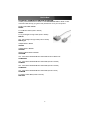
PCI Serial Card
2 Port High-Speed RS-232 Powered PCI Serial Card
4 Port High-Speed RS-232 Powered PCI Serial Card
PCI2S650PW
PCI4S650PW
Instruction Manual
FCC Compliance Statement
This equipment has been tested and found to comply with the limits for a Class B digital
device, pursuant to part 15 of the FCC Rules. These limits are designed to provide
reasonable protection against harmful interference in a residential installation. This
equipment generates, uses and can radiate radio frequency energy and, if not installed
and used in accordance with the instructions, may cause harmful interference to radio
communications. However, there is no guarantee that interference will not occur in a
particular installation. If this equipment does cause harmful interference to radio or
television reception, which can be determined by turning the equipment off and on, the
user is encouraged to try to correct the interference by one or more of the following
measures:
• Reorient or relocate the receiving antenna.
• Increase the separation between the equipment and receiver.
• Connect the equipment into an outlet on a circuit different from that to which the
receiver is connected.
• Consult the dealer or an experienced radio/TV technician for help.
Use of Trademarks, Registered Trademarks, and other
Protected Names and Symbols
This manual may make reference to trademarks, registered trademarks, and other
protected names and/or symbols of third-party companies not related in any way to
StarTech.com. Where they occur these references are for illustrative purposes only and
do not represent an endorsement of a product or service by StarTech.com, or an
endorsement of the product(s) to which this manual applies by the third-party company in
question. Regardless of any direct acknowledgement elsewhere in the body of this
document, StarTech.com hereby acknowledges that all trademarks, registered
trademarks, service marks, and other protected names and/or symbols contained in this
manual and related documents are the property of their respective holders.
Instruction Manual
Table of Contents
Introduction . . . . . . . . . . . . . . . . . . . . . . . . . . . . . . . . . . . . . . . . . . . . . . . . . . . . .1
Before You Begin . . . . . . . . . . . . . . . . . . . . . . . . . . . . . . . . . . . . . . . . . . . . . . . .1
System Requirements . . . . . . . . . . . . . . . . . . . . . . . . . . . . . . . . . . . . . . . . . . .1
Contents . . . . . . . . . . . . . . . . . . . . . . . . . . . . . . . . . . . . . . . . . . . . . . . . . . . . .1
Installation . . . . . . . . . . . . . . . . . . . . . . . . . . . . . . . . . . . . . . . . . . . . . . . . . . . . . .2
Installing the Card . . . . . . . . . . . . . . . . . . . . . . . . . . . . . . . . . . . . . . . . . . . . . .2
Configuring the Jumpers: PCI2S650PW . . . . . . . . . . . . . . . . . . . . . . . . . . . . .3
Configuring the Jumpers: PCI4S650PW . . . . . . . . . . . . . . . . . . . . . . . . . . . . .4
Installing the Drivers . . . . . . . . . . . . . . . . . . . . . . . . . . . . . . . . . . . . . . . . . . . .5
Verifying Your Installation . . . . . . . . . . . . . . . . . . . . . . . . . . . . . . . . . . . . . . . .5
Specifications . . . . . . . . . . . . . . . . . . . . . . . . . . . . . . . . . . . . . . . . . . . . . . . . . . .6
Accessory Products from StarTech.com . . . . . . . . . . . . . . . . . . . . . . . . . . . . .7
Technical Support . . . . . . . . . . . . . . . . . . . . . . . . . . . . . . . . . . . . . . . . . . . . . . . .8
Warranty Information . . . . . . . . . . . . . . . . . . . . . . . . . . . . . . . . . . . . . . . . . . . . .8
i
Instruction Manual
Introduction
Thank you for purchasing a StarTech.com powered PCI serial card. This product adds
high speed serial ports to your computer, and includes 5 and 12 volt power support for
connected peripherals. For added flexibility this card also supports 5 volt (32-bit PCI)
and 3.3 volt (64-bit PCI-X) computer interfaces, and includes drivers for 64-bit editions of
Windows.
Features
• Adds high speed RS-232 serial ports to your computer
• Additional power connector to support 5 or 12 volt self-powered serial peripherals
• Works in both standard 32-bit (5 volt) PCI and 64-bit (3.3 volt) PCI-X expansion slots
• Provides transfer rates of up to 920 Kbits/sec, supports half and full duplex
• Fully Plug and Play compliant for easy setup and configuration
Before You Begin
System Requirements
• A computer running Windows 2003/XP/2000/NT/ME/98SE/98/95, DOS/Windows 3.1,
Linux/UNIX
• An available standard or low-profile PCI or PCI-X slot
•
A CD-ROM or other optical drive (for driver software installation)
Contents
This package should contain:
• 1 x PCI serial card (includes a low-profile slot bracket)
• 1 x Installation CD
• 1 x 2-port or 4-port DB9 “dongle” connector
• 1 x Instruction Manual
WARNING! PCI cards, like all computer equipment, can be severely damaged by static
electricity. Be sure that you are properly grounded before opening your computer case or
touching your PCI card. StarTech.com recommends that you wear an anti-static strap
when installing any computer component. If an anti-static strap is unavailable, discharge
yourself of any static electricity build-up by touching a large grounded metal surface
(such as the computer case) for several seconds. Also be careful to handle the PCI card
by its edges and not the gold connectors.
1
Instruction Manual
Installation
This section will guide you through the installation of your PCI card and the related
software. Please read through the instructions carefully and complete each step in the
order listed.
Installing the Card
PCI
Slots
1. Make sure that your system is unplugged and you are grounded.
2. Remove the cover of your system (see your computer’s user manual for details, if
necessary) and gently turn your computer onto its side.
3. (a) Locate an empty PCI or PCI-X slot (usually white in color) and remove the metal
plate that covers the rear bracket. If present, PCI-X slots will be slightly longer than a
standard PCI slot. You may need a Phillips screwdriver to perform this step.
Retain this screw! You will need it to secure the card later.
(b) If you are installing the card in a low-profile slot, remove the standard bracket by
removing the screws on the underside of the card. Place the low-profile bracket onto
the card and align the holes in the card with those in the bracket. Ensure the
orientation of the new bracket matches the one you removed. Re-secure the bracket
with the screws. Do not over-tighten.
4. Gently insert the card into the empty slot, making sure it is firmly seated.
5. Secure the card in place using the screw you removed in Step 3.
6. If you wish to use this card to power compatible external serial peripherals
over a data connection, you should also connect a power cable from your
power supply to the 4-pin SP4 power connector on the outer edge of the
card. The SP4 power connector is the same type of power
connector commonly used to power 3.5” floppy disk drives (see example of
the card connector at right).
7. Connect the port dongle provided to the port on the back of the card.
8. Put your computer case back on.
2
SP4
Instruction Manual
Configuring the Jumpers: PCI2S650PW
The card uses jumpers to set
internal and external power
voltages, and to configure
which serial ports will receive
5v, 12v, or RI signal
(unpowered) through the 9th
pin.
J2: Sets internal (bus) voltage
and the external power drawn
through the SP4 power
connector (external)
J4 and J5: Sets voltage for
each individual DB9 port
Power
Supply
Int5V
Int12V
Int5V
Ext12
Ext5V
Int12V
Ext5V
Ext12V
J2
J2
J2
J2
5 VP
5 VA
12VA
12VP
5 VP
5 VA
12VA
12VP
5 VP
5 VA
12VA
12VP
5 VP
5 VA
12VA
12VP
Jumper Setting
*Please select 5V, 12V, or RI Signal for COM1and COM2 using J4 and J5
5V
12V
RI
J4 and J5
Jumper Setting
+12W +5V
RI
+12W +5V
RI
+12W +5V
Failure to observe these warnings could cause damage to
the serial card, computer, and peripherals.
Do not set the jumpers J4 and J5 to supply
both 5v and 12v power at the same time.
Ensure jumper caps are placed vertically in line
with the markings on the board, not “across”
settings.
3
RI
Instruction Manual
Configuring the Jumpers: PCI4S650PW
The card uses jumpers to set
internal and external power
voltages, and to configure
which serial ports will receive
5v, 12v, or RI signal
(unpowered) through the 9th
pin.
J6: Sets internal (bus) voltage
and the external power drawn
through the SP4 power
connector (external)
J2 thru J5: Sets voltage for
each individual DB9 port
Power
Supply
Int5V
Int12V
Int5V
Ext12
Ext5V
Int12V
Ext5V
Ext12V
J6
J6
J6
J6
5 VP
5 VA
12VA
12VP
5 VP
5 VA
12VA
12VP
5 VP
5 VA
12VA
12VP
5 VP
5 VA
12VA
12VP
Jumper Setting
*Please select 5V, 12V, or RI Signal for COM1~COM4 using J2~J5
5V
12V
RI
J2 - J5
Jumper Setting
+12W +5V
RI
+12W +5V
RI
+12W +5V
Failure to observe these warnings could cause damage to
the serial card, computer, and peripherals.
Do not set any of the jumpers J2-J5 to supply
both 5v and 12v power at the same time.
Ensure jumper caps are placed vertically in line
with the markings on the board, not “across”
settings.
4
RI
Instruction Manual
Installing the Drivers
If you lose your driver disk, these drivers are available as a free download from our
website. Visit www.startech.com and click on the Downloads link for more information.
Windows 95/98/ME
1. Windows will detect that new hardware is installed and launch the Add New
Hardware Wizard. Click Next and choose the Search for the best driver for your
device (Recommended) option. Click Next.
2. On the next screen select only Specify a location. Choose Browse.
3. In the file selection box, double click the win9x folder under CD-ROM Drive (X:).
Click OK. The drive letter and name of the drive where the CD is located may
depend on your system configuration.
4. The file location box under Specify a location will now contain the path to the files.
Click Next.
5. The Wizard will inform you that “Windows is now ready to install the best driver for
this device...” Click Next. The Wizard will complete the installation. Click
Finish.
Windows 2000/XP/2003 (includes 64-bit editions)
1. Windows will launch the Add New Hardware Wizard. Click Next.
2. Choose the Search for a suitable driver... option and click Next.
3. Check only the CD-ROM drives option. Ensure the installation disk is inserted in
the floppy drive. Click Next..
4. Windows will display a message stating that “Windows has found a driver for this
device”. Click Next. (If you are presented with multiple choices for the driver, choose
the driver file in the \IO\PCI IO\WHQL Driver for 2K_XP_2003 folder.) Choose Yes or
Continue Anyway if you are warned that the driver file has not been digitally signed.
5. WIndows will display a message that states “Windows has finished installing software
for this device”. Click Finish.
6. Windows will continue to detect and install any remaining new devices. If the Add
New Hardware Wizard is launched again, repeat steps 1 through 5 from above.
Other Operating Systems
For installation of the serial card’s software under other operating systems (Windows NT
DOS/Windows 3.1, Linux etc.) please consult the documentation contained in the
appropriate folder for your OS located inside the \IO\PCI IO\ directory on the installation
CD.
Verifying Your Installation
Windows 95/98/ME
1. Go to Start > Settings > Control Panel.
5
Instruction Manual
2. Double click System.
3. Click the Hardware tab.
4. If the card does not appear with a red x or yellow exclamation point (!) next to it,
Windows has not detected a problem with the installation and the card should
function normally.
Windows 2000/XP/2003
1. Go to Start > Settings > Control Panel.
2. Double click System.
3. Click the Hardware tab and choose Device Manager.
4. If the card does not appear with a red x or yellow exclamation point (!) next to it,
Windows has not detected a problem with the installation and the card should
function normally.
Specifications
Card Interface
FIFO Size
32-bit PCI (5v), 64-bit PCI-X (3.3v)
128 KBytes software, 32 bytes hardware
Max. Data Transfer Rate
920 Kbits/sec., supports half and full duplex
Connectors
1 x proprietary 44-pin (female) to dongle
2 x DB9 (male) to peripherals (PCI2S650PW)
4 x DB9 (male) to peripherals (PCI4S650PW)
1 x internal SP4 (male) power connector
TxD, RxD, RTS, CTS, DTR, DSR, DCD, RI, GND (see below for pinout)
5 or 12 volts to peripheral supported over DB9 connection
Windows 2003 Server, XP, 2000, NT, ME, 98, 95, DOS/Windows 3.1, Linux
(Driver support included for 64-bit editions of Windows 2003 and 2000 Server.)
Signals Supported (RS-232)
Power to Peripherals
OS Support
Operating Tolerances
32º~135ºF (0º~57ºC), 5~95% rel. humidity
UART Chipset
Sunix SUN1889 (16C650 compliant)
Certifications
Regulatory: FCC Class B, CE Other: Microsoft WHQL
Pin
1
1
9
25
1
2
3
4
5
6
7
8
9
20
22
DB9
Assignment
DCD
RD
TD
DTR
GROUND
DSR
RTS
CTS
RI / 5V / 12V
n/a
n/a
DB25
Assignment
NC
TD
RD
RTS
CTS
DSR
GROUND
CD
n/a
DTR
RI / 5V / 12V
(Any unshown pins are not used.)
6
Instruction Manual
Accessory Products from StarTech.com
Contact your local StarTech.com dealer or visit www.startech.com for cables or other
accessories that will help you get the best performance out of your new product.
Modem Cable DB9F-DB25M
MC3MF
6 ft. AT Modem Cable (male to female)
MC6MF
6 ft. 9-pin Straight Through Cable (male to female)
MXT100
25 ft. 9-pin Straight Through Cable (male to female)
MXT100_25
Adapter DB9F to DB25F
AT925FF
Adapter DB9F to DB25M
AT925FM
Slimline Adapter DB9F to DB25M
AT925SFM
10 ft. Cross Wired Serial/Null Modem Cable DB9 female to DB25 male
SCNM925FM
10 ft. Cross Wired Serial/Null Modem Cable DB9 (female to female)
SCNM9FF
25 ft. Cross Wired Serial/Null Modem Cable DB9 (female to female)
SCNM9FF25
10 ft. Cross Wired Serial/Null Modem Cable DB9 (female to male)
SCNM9FM
6 ft. Modem Cable DB9 (female to female)
MXT100FF
7
Instruction Manual
Technical Support
StarTech.com’s lifetime technical support is an integral part of our commitment to provide
industry-leading solutions. If you ever need help with your product, visit
www.startech.com/support and access our comprehensive selection of online tools,
documentation, and downloads.
Warranty Information
This product is backed by a lifetime warranty. In addition, StarTech.com warrants its
products against defects in materials and workmanship for the periods noted, following
the initial date of purchase. During this period, the products may be returned for repair, or
replacement with equivalent products at our discretion. The warranty covers parts and
labor costs only. StarTech.com does not warrant its products from defects or damages
arising from misuse, abuse, alteration, or normal wear and tear.
Limitation of Liability
In no event shall the liability of StarTech.com Ltd. and StarTech.com USA LLP (or their
officers, directors, employees or agents) for any damages (whether direct or indirect,
special, punitive, incidental, consequential, or otherwise), loss of profits, loss of business,
or any pecuniary loss, arising out of or related to the use of the product exceed the
actual price paid for the product.
Some states do not allow the exclusion or limitation of incidental or consequential
damages. If such laws apply, the limitations or exclusions contained in this statement
may not apply to you.
8
About StarTech.com
StarTech.com is “The Professionals’ Source for Hard-to-Find Computer
Parts”. Since 1985, we have been providing IT professionals with the
quality products they need to complete their solutions. We offer an
unmatched selection of computer parts, cables, server management
solutions and A/V products and serve a worldwide market through our
locations in the United States, Canada, the United Kingdom and Taiwan.
Revised: 20 January 2005 (Rev. A)