1
Hardware Installation Guide
for the Polycom SoundStructure
C16, C12, C8, and SR12
1725-33169-001
Revision A
Trademark Information
Polycom®, the Polycom logo design, SoundPoint® IP, SoundStation®, SoundStation VTX 1000®, ViaVideo®,
ViewStation®, and Vortex® are registered trademarks of Polycom, Inc. Polycom HD Voice™, Conference Composer™,
Global Management System™, ImageShare™, Instructor RP™, iPower™, MGC™, PathNavigator™,
People+Content™, PowerCam™, Pro-Motion™, QSX™, ReadiManager™, Siren™, StereoSurround™, V2IU™, Visual
Concert™, VS4000™, VSX™, SoundStructure™, and the industrial design of SoundStation are trademarks of Polycom,
Inc. in the United States and various other countries. All other trademarks are the property of their respective owners.
Patent Information
The accompanying product is protected by one or more U.S. and foreign patents and/or pending patent applications
held by Polycom, Inc.
Disclaimer
Some countries, states, or provinces do not allow the exclusion or limitation of implied warranties or the limitation of
incidental or consequential damages for certain products supplied to consumers, or the limitation of liability for personal
injury, so the above limitations and exclusions may be limited in their application to you. When the implied warranties
are not allowed to be excluded in their entirety, they will be limited to the duration of the applicable written warranty. This
warranty gives you specific legal rights which may vary depending on local law.
Copyright Notice
Permission is hereby granted, free of charge, to any person obtaining a copy of this software and associated
documentation files (the “Software”), to deal in the Software without restriction, including without limitation the rights to
use, copy, modify, merge, publish, distribute, sublicense, and/or sell copies of the Software, and to permit persons to
whom the Software is furnished to do so, subject to the following conditions:
The above copyright notice and this permission notice shall be included in all copies or substantial portions of the
Software.
THE SOFTWARE IS PROVIDED “AS IS”, WITHOUT WARRANTY OF ANY KIND, EXPRESS OR IMPLIED,
INCLUDING BUT NOT LIMITED TO THE WARRANTIES OF MERCHANTABILITY, FITNESS FOR A PARTICULAR
PURPOSE AND NONINFRINGEMENT. IN NO EVENT SHALL THE AUTHORS OR COPYRIGHT HOLDERS BE
LIABLE FOR ANY CLAIM, DAMAGES OR OTHER LIABILITY, WHETHER IN AN ACTION OF CONTRACT, TORT OR
OTHERWISE, ARISING FROM, OUT OF OR IN CONNECTION WITH THE SOFTWARE OR THE USE OR OTHER
DEALINGS IN THE SOFTWARE.
© 2007 Polycom, Inc. All rights reserved.
Polycom Inc.
4750 Willow Road
Pleasanton, CA 94588-2708
USA
No part of this document may be reproduced or transmitted in any form or by any means, electronic or mechanical, for
any purpose, without the express written permission of Polycom, Inc. Under the law, reproducing includes translating
into another language or format.
As between the parties, Polycom, Inc. retains title to, and ownership of, all proprietary rights with respect to the software
contained within its products. The software is protected by United States copyright laws and international treaty
provision. Therefore, you must treat the software like any other copyrighted material (e.g. a book or sound recording).
Every effort has been made to ensure that the information in this manual is accurate. Polycom, Inc. is not responsible
for printing or clerical errors. Information in this document is subject to change without notice.
Contents
Preparing For Installation . . . . . . . . . . . . . . . . . . . . . . . . . . . . . . . . . . 1–1
Overview . . . . . . . . . . . . . . . . . . . . . . . . . . . . . . . . . . . . . . . . . . . . . . . . . . . . .
Product Features . . . . . . . . . . . . . . . . . . . . . . . . . . . . . . . . . . . . . . . . . . . . . . . . . . . . . .
Installation Overview . . . . . . . . . . . . . . . . . . . . . . . . . . . . . . . . . . . . . . . . . . . .
Package Contents . . . . . . . . . . . . . . . . . . . . . . . . . . . . . . . . . . . . . . . . . . . . . . .
Tools Needed For Installation . . . . . . . . . . . . . . . . . . . . . . . . . . . . . . . . . . . . . . .
Safety Recommendations . . . . . . . . . . . . . . . . . . . . . . . . . . . . . . . . . . . . . . . . . .
General Site Requirements . . . . . . . . . . . . . . . . . . . . . . . . . . . . . . . . . . . . . . . . .
Power Supply Considerations . . . . . . . . . . . . . . . . . . . . . . . . . . . . . . . . . . . . . . . . . . .
1–1
1–2
1–2
1–3
1–5
1–5
1–6
1–6
Installing The SoundStructure C16, C12, C8, And SR12 . . . . . . . . . . . . 2–1
Panel Diagrams . . . . . . . . . . . . . . . . . . . . . . . . . . . . . . . . . . . . . . . . . . . . . . . . 2–1
Front-Panel . . . . . . . . . . . . . . . . . . . . . . . . . . . . . . . . . . . . . . . . . . . . . . . . . . . . . . . . . . . 2–2
Rear Panel . . . . . . . . . . . . . . . . . . . . . . . . . . . . . . . . . . . . . . . . . . . . . . . . . . . . . . . . . . . 2–3
Installing The Hardware . . . . . . . . . . . . . . . . . . . . . . . . . . . . . . . . . . . . . . . . . . 2–3
Plug-in Card Installation . . . . . . . . . . . . . . . . . . . . . . . . . . . . . . . . . . . . . . . . . . . . . . . 2–4
Rack-Mounting The Polycom SoundStructure Device . . . . . . . . . . . . . . . . . . . . . . 2–6
Connecting To The LAN Interface . . . . . . . . . . . . . . . . . . . . . . . . . . . . . . . . . . . . . . . 2–7
Connecting To Other Polycom Equipment With Conference Link2 . . . . . . . . . . . 2–7
Using Multiple SoundStructure Devices With OBAM Link Interface . . . . . . . . . 2–9
Connecting IR Port To Optional Receiver And/Or RS-232 To Control System 2–12
Making Audio Connections . . . . . . . . . . . . . . . . . . . . . . . . . . . . . . . . . . . . . . . . . . . 2–14
Connecting Logic Ports . . . . . . . . . . . . . . . . . . . . . . . . . . . . . . . . . . . . . . . . . . . . . . . 2–15
Powering Up The System . . . . . . . . . . . . . . . . . . . . . . . . . . . . . . . . . . . . . . . . . . . . . 2–19
Configuring The SoundStructure Devices . . . . . . . . . . . . . . . . . . . . . . . . . . . . . . . 2–20
Specifications . . . . . . . . . . . . . . . . . . . . . . . . . . . . . . . . . . . . . . . . . . . 3–1
Technical Specifications . . . . . . . . . . . . . . . . . . . . . . . . . . . . . . . . . . . . . . . . . . .
Pin Out Summary . . . . . . . . . . . . . . . . . . . . . . . . . . . . . . . . . . . . . . . . . . . . . . .
Conference Link2 . . . . . . . . . . . . . . . . . . . . . . . . . . . . . . . . . . . . . . . . . . . . . . . . . . . . .
OBAM Link . . . . . . . . . . . . . . . . . . . . . . . . . . . . . . . . . . . . . . . . . . . . . . . . . . . . . . . . . .
IR Receiver . . . . . . . . . . . . . . . . . . . . . . . . . . . . . . . . . . . . . . . . . . . . . . . . . . . . . . . . . . .
RS-232 . . . . . . . . . . . . . . . . . . . . . . . . . . . . . . . . . . . . . . . . . . . . . . . . . . . . . . . . . . . . . . .
3–1
3–4
3–4
3–5
3–6
3–6
1
Hardware Installation Guide for the Polycom SoundStructure
Logic Interface . . . . . . . . . . . . . . . . . . . . . . . . . . . . . . . . . . . . . . . . . . . . . . . . . . . . . . . . 3–7
Audio Connections . . . . . . . . . . . . . . . . . . . . . . . . . . . . . . . . . . . . . . . . . . . . . . . . . . . . 3–8
Logic Examples . . . . . . . . . . . . . . . . . . . . . . . . . . . . . . . . . . . . . . . . . . 4–1
Logic Input . . . . . . . . . . . . . . . . . . . . . . . . . . . . . . . . . . . . . . . . . . . . . . . . . . . .
Contact Closure . . . . . . . . . . . . . . . . . . . . . . . . . . . . . . . . . . . . . . . . . . . . . . . . . . . . . . .
Logic Output . . . . . . . . . . . . . . . . . . . . . . . . . . . . . . . . . . . . . . . . . . . . . . . . . . .
SoundStructure Powered Relay . . . . . . . . . . . . . . . . . . . . . . . . . . . . . . . . . . . . . . . . .
Externally Powered Relay . . . . . . . . . . . . . . . . . . . . . . . . . . . . . . . . . . . . . . . . . . . . . .
Driving An LED . . . . . . . . . . . . . . . . . . . . . . . . . . . . . . . . . . . . . . . . . . . . . . . . . . . . . .
Logic Input And Output . . . . . . . . . . . . . . . . . . . . . . . . . . . . . . . . . . . . . . . . . . .
Push To Talk Microphones . . . . . . . . . . . . . . . . . . . . . . . . . . . . . . . . . . . . . . . . . . . . .
Analog Gain Control . . . . . . . . . . . . . . . . . . . . . . . . . . . . . . . . . . . . . . . . . . . . .
4–1
4–1
4–2
4–2
4–2
4–3
4–4
4–4
4–5
Accessories . . . . . . . . . . . . . . . . . . . . . . . . . . . . . . . . . . . . . . . . . . . . . 5–1
Regulatory Notices And Warranty Information . . . . . . . . . . . . . . . . . . . 6–1
Regulatory Notices . . . . . . . . . . . . . . . . . . . . . . . . . . . . . . . . . . . . . . . . . . . . . . 6–1
USA And Canada . . . . . . . . . . . . . . . . . . . . . . . . . . . . . . . . . . . . . . . . . . . . . . . . . . . . . 6–1
Exhibit J - Customer Information . . . . . . . . . . . . . . . . . . . . . . . . . . . . . . . . . . . . . . . . 6–2
Data Equipment . . . . . . . . . . . . . . . . . . . . . . . . . . . . . . . . . . . . . . . . . . . . . . . . . . . . . . 6–3
Canada . . . . . . . . . . . . . . . . . . . . . . . . . . . . . . . . . . . . . . . . . . . . . . . . . . . . . . . . . . . . . . 6–3
EEA (European Economic Area) Including Switzerland . . . . . . . . . . . . . . . . . . . . 6–4
Australia . . . . . . . . . . . . . . . . . . . . . . . . . . . . . . . . . . . . . . . . . . . . . . . . . . . . . . . . . . . . . 6–8
Japan (VCCI) . . . . . . . . . . . . . . . . . . . . . . . . . . . . . . . . . . . . . . . . . . . . . . . . . . . . . . . . . 6–8
Korea . . . . . . . . . . . . . . . . . . . . . . . . . . . . . . . . . . . . . . . . . . . . . . . . . . . . . . . . . . . . . . . . 6–9
Rest Of World . . . . . . . . . . . . . . . . . . . . . . . . . . . . . . . . . . . . . . . . . . . . . . . . . . . . . . . . 6–9
Warranty Information . . . . . . . . . . . . . . . . . . . . . . . . . . . . . . . . . . . . . . . . . . . 6–10
2
1
Preparing For Installation
This chapter introduces the Polycom® SoundStructure™ C16, C12, and C8
audio conferencing devices, and the SoundStructure SR12, a sound
reinforcement product which is compatible with the Polycom SoundStructure
C16, C12, and C8.
This chapter contains the steps to follow before installing this new hardware
and includes information on:
•
Overview
•
Installation Overview
•
Tools Needed For Installation
•
General Site Requirements
To install the Polycom SoundStructure hardware, refer to Installing The
Hardware on page 2-3.
Overview
The Polycom SoundStructure C16, C12, and C8 audio conferencing devices are
audio processing devices that have 16 inputs and 16 outputs (C16), 12 inputs
and 12 outputs (C12), and 8 inputs and 8 outputs (C8).
The C16, C12, and C8 versions of this product line features acoustic echo
cancellation (AEC), noise cancellation, automatic microphone mixing, matrix
mixing, equalization, feedback elimination, dynamics processing, delay, and
submix processing.
The SR12 does not include acoustic echo cancellation processing but does
includes noise cancellation, automatic microphone mixing, matrix mixing,
equalization, feedback elimination, dynamics processing, delay, and submix
processing.
All the SoundStructure products provide 24-bit A-D/D-A subsystems, 48 kHz
sampling, and a dynamic range exceeding 100 dB. Two different Public
Switched Telephone Network (PSTN) interfaces, a single-line and dual-line,
are available.
1-1
Hardware Installation Guide for the Polycom SoundStructure C16, C12, C8 and SR12
Product Features
The Polycom SoundStructure C16, C12, C8 and SR12 offer the following
features:
•
16 (C16), 12 (C12 and SR12), or 8 (C8) balanced Microphone/line-level
inputs
•
48 V phantom power available on all inputs
•
16 (C16), 12 (C12 and SR12), or 8 (C8) balanced line-level outputs
•
Rear-panel Ethernet and RS-232 interfaces
•
Optional telephone interface cards
•
High-speed OBAM link to connect up to eight SoundStructure devices
(requires firmware v1.1 or higher)
•
High-speed link to connect directly to Polycom HDX video codecs
Installation Overview
To prepare for the installation of the Polycom SoundStructure hardware:
1-2
•
Review the safety information in Safety Recommendations on page 1-5,
and in Regulatory Notices And Warranty Information on page 6-1.
•
Unpack the hardware carefully. The contents included in the shipping
container are listed in the next section, Package Contents, and Tools
Needed For Installation on page 1-5. If any components are missing,
contact your Polycom reseller.
Preparing For Installation
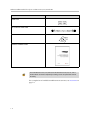
Package Contents
The SoundStructure products include the components shown below.
SoundStructure Device
3.5mm Terminal Blocks
Rack Ears and Rack-Mounting Screws
12” OBAM Cable
Power Cable
Conference Link2 insert plugs
1-3
Hardware Installation Guide for the Polycom SoundStructure C16, C12, C8 and SR12
Rubber Feet
18” Conference Link2 Cable
Software CD
Hardware Installation Guide
Warning
The SoundStructure C16, C12, SR12, and C8 devices have 33, 25, 25, and 17
terminal block connectors respectively including one for the optional IR receiver
accessory.
For a complete list of available SoundStructure Accessories, see Accessories on
page 5-1.
1-4
Preparing For Installation
Tools Needed For Installation
The following tools will be required to install your Polycom SoundStructure
unit:
•
A Phillips head screwdriver for installing rack ears and rack-mounting the
device.
•
A small blade screwdriver for terminating audio cables to the terminal
blocks.
Safety Recommendations
Read and understand the following instructions before using the system:
•
Always disconnect the system from power before inserting plug-in cards
into the SoundStructure device.
•
Only connect the system to surge protected power outlets.
•
Only use electrical extension cords with a current rating at least equal to
that of the system.
•
Always disconnect the system from power before cleaning and servicing
and when not in use.
•
Do not spray liquids directly onto the system when cleaning. Always
apply the liquid first to a static free cloth.
•
Do not immerse the system in any liquid or place any liquids on it.
•
Do not disassemble this system. To reduce the risk of shock and to
maintain the warranty on the system, a qualified technician must perform
service or repair work.
•
Keep ventilation openings free of any obstructions.
•
If the system or any accessories are installed in an enclosed space such as
a cabinet or equipment rack, ensure that the air temperature in the
enclosure does not exceed 40° C (104° F). Forced cooling may be required
to keep the equipment within its operating temperature range.
Save these safety instructions.
Warning
1-5
Hardware Installation Guide for the Polycom SoundStructure C16, C12, C8 and SR12
General Site Requirements
Please ensure the SoundStructure side ventilation holes have at least 1 inch of
clearance from the sides of the rack to allow airflow through the device.
Failure to maintain clearance for airflow may increase the operating
temperature of the unit beyond its maximum operating temperature of 40° C
(104° F).
With the proper side clearance, each SoundStructure device requires one rack
space and does not require additional empty rack spaces above or below the
device. When mounting with other equipment give consideration to having
access to the audio connectors on the rear-panel.
When using SoundStructure with Polycom HDX video codecs, it is
recommended that the SoundStructure devices be installed above the video
codec.
If you are placing the device on a tabletop or other flat surface (rather than
rack- mounting it), it is recommended to mount the adhesive rubber feet on the
bottom of the device as shown in Rack-Mounting The Polycom
SoundStructure Device to prevent damaging the finish of the furniture
surface.
Power Supply Considerations
The Polycom SoundStructure C16, C12, C8 and SR12 have the following
power requirements on the line power supplied to the devices:
•
Input voltage of 90-250 VAC; 50-60 Hz
•
Line power requirements (including 0.6 PF):
— 130 VA (C16),
— 115 VA (C12),
— 105 VA (SR12),
— 95 VA (C8)
1-6
2
Installing The SoundStructure C16,
C12, C8, And SR12
This chapter provides information on the Polycom SoundStructure product,
rack-mount, and installation procedures.
•
Panel Diagrams
•
Installing The Hardware
Panel Diagrams
This section describes the front and rear-panels of the Polycom
SoundStructure C16.
Warning
The graphics shown in this guide show the Polycom SoundStructure C16 audio
conferencing device. The SoundStructure C12, C8, and SR12 are all very similar in
appearance to the C16.
2-1
Hardware Installation Guide for the Polycom SoundStructure C16, C12, C8, And SR12
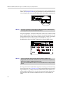
Front-Panel
The front-panel of the Polycom SoundStructure C16 is shown below with the
front panel door open, revealing the serial number label and the System Status
LED.
TM
SoundStructure C16
Serial number on
Front panel door
System Status LED
Front-Panel LED Interpretation
The front-panel LEDs are interpreted as follows:
2-2
LED
Color
State
Description
Status
Green
Flashing
The system is
starting up.
Solid
The system is
operating normally.
Yellow
Solid
The system has
logged a warning
and the system logs
should be reviewed.
Red
Solid
A system
component has
failed and requires
immediate
attention.
Installing The SoundStructure C16, C12, C8, And SR12
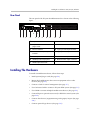
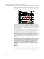
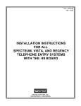
Rear Panel
The rear-panel of the Polycom SoundStructure C16 is shown in the following
figure.
C-LINK2
IN
OBAM
2
3
4
4
5
6
7
8
9
10
11
12
13
14
15
16
1
2
3
4
5
6
7
8
9
10
11
12
13
14
15
16
SoundStructureTM C16
7
5
1
3
REMOTE CONTROL 2
IR 12V
OUT
2
INPUTS
LAN
1
REMOTE CONTROL 1
RS-232
OUTPUTS
PIN 2: TXD
PIN 3: RXD
PIN 5: GROUND
PIN 7: CTS
PIN 8: RTS
6
8
9
10
11
12
13
1
AC power connection
8
IR receiver interface
2
Expansion slot for SoundStructure
plug-in cards
9
RS-232 interface
3
Ethernet interface
10 Logic input and output connector
4
Conference Link2 (CLink2)
interface
11 Logic input and output connector 2
5
OBAM input status LED
12 Balanced audio input connectors
6
OBAM input and output ports
13 Balanced audio output connectors
7
OBAM output status LED
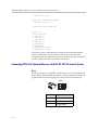
Installing The Hardware
To install a SoundStructure device, follow these steps:
•
Install optional plug-in card. (See page 2-4.)
•
Mount the SoundStructure device onto an equipment rack or other
location. (See page 2-6.)
•
Connect to LAN for control management. (See page 2-7.)
•
Use Conference Link2 to connect to Polycom HDX system. (See page 2-7.)
•
Use OBAM to connect multiple SoundStructure devices. (See page 2-9.)
•
Connect IR port to optional receiver and/or RS-232 to control system. (See
page 2-12.)
•
Connect other devices/equipment using analog input/output. (See page
2-14.)
•
Connect optional logic devices. (See page 2-15.)
2-3
Hardware Installation Guide for the Polycom SoundStructure C16, C12, C8, And SR12
•
Connect AC power. (See page 2-19.)
•
Configure devices using SoundStructure Studio software. (See page 2-20.)
Plug-in Card Installation
Each SoundStructure device can have a plug-in card installed for a total of
eight plug-in cards in a collection of eight SoundStructure devices. When
installing more than one plug-in card in an installation, it is recommended to
use the plug-in slot from the top device first and continue sequentially down
through the collection of devices as additional plug-cards are added.
Warning
Do not insert a plug-in card while the SoundStructure is powered on.
Failure to remove power prior to installing the plug-in card may damage the plug-in
card and/or the SoundStructure device.
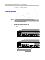
To install a plug-in card, follow these five steps:
1. If plugged in, unplug the AC power cord from the SoundStructure
device.
PIN 2: TXD
PIN 3: RXD
PIN 5: GROUND
PIN 7: CTS
PIN 8: RTS
RS-232
LAN
C-LINK2
IN
OBAM
OUT
IR 12V
2. Remove the blank plate and screws from the expansion slot (see below).
PIN 2: TXD
PIN 3: RXD
PIN 5: GROUND
PIN 7: CTS
PIN 8: RTS
RS-232
LAN
2-4
C-LINK2
IN
OBAM
OUT
IR 12V
Installing The SoundStructure C16, C12, C8, And SR12
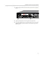
3. Insert the plug-in card into the slotted rails and push until it is tight into
the slot.
PHONE
LINE
PIN 2: TXD
PIN 3: RXD
PIN 5: GROUND
PIN 7: CTS
PIN 8: RTS
RS-232
LAN
C-LINK2
IN
OBAM
OUT
IR 12V
4. Tighten the thumbscrews on the rear-panel of the plug-in card.
5. If no further installation steps are required, plug in the AC power cable;
otherwise, continue with the remainder of the installation steps prior to
applying power.
2-5
Hardware Installation Guide for the Polycom SoundStructure C16, C12, C8, And SR12
Rack-Mounting The Polycom SoundStructure Device
The Polycom SoundStructure can be mounted in an equipment rack, or placed
on a tabletop or other flat surface, or mounted under the table with the
optional undertable mounting kit.
Each SoundStructure device requires one rack space and does not require
additional empty rack spaces above or below the device.
Warning
When multiple devices are racked together, before final tightening of the rack mount
screws on each device after the first one, ensure there is enough clearance so that
the front-panel door will open freely.
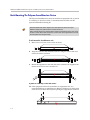
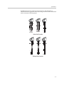
To rack-mount the SoundStructure unit:
1. Remove the four front screws on the enclosure.
TM
SoundStructure C16
2. Align the rack ears, and install the rack ears using the screws that were
removed from the enclosure.
TM
SoundStructure C16
3. Mount the equipment in the rack and secure with the four supplied rack
mount screws (screw size is 10-32x1/2").
TM
SoundStructure C16
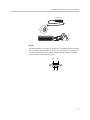
To place on a tabletop or other flat surface:
>> If the equipment will not be mounted in an equipment rack, it is
recommended that you install the four adhesive rubber feet on the bottom
of the device (as shown below) before placing the equipment on furniture.
2-6
Installing The SoundStructure C16, C12, C8, And SR12
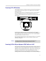
Connecting To The LAN Interface
The SoundStructure device's Ethernet interface (as shown following figure) is
a 10/100 Mbps interface that supports Auto-MDIX (medium dependent
interface crossover).
Auto-MDIX enables the use of a standard CAT5e cable to connect directly
from the SoundStructure device to either an Ethernet network or to a
computer. The SoundStructure device will detect the connection and work
appropriately.
PIN 2: TXD
PIN 3: RXD
PIN 5: GROUND
PIN 7: CTS
PIN 8: RTS
RS-232
LAN
C-LINK2
IN
OBAM
OUT
IR 12V
1
2
1
2
REMOTE CONTROL 1
REMOTE CONTROL 2
LAN
By default the SoundStructure device has Dynamic Host Configuration
Protocol (DHCP) enabled and will accept an IP address from a DHCP server.
The SoundStructure device IP address can also be set to a static IP address
using the SoundStructure Studio software.
Do not plug the Ethernet cable in to the Conference Link2 ports. To minimize
improper cabling, plastic plugs have been installed by default into the
Conference Link2 ports.
Warning
Connecting an Ethernet cable into the Conference Link2 interface of a
SoundStructure device could damage the SoundStructure device.
Connecting To Other Polycom Equipment With Conference Link2
The Conference Link2 interface (shown in the following drawing and labeled
C-Link2) is used to connect the SoundStructure devices to other Polycom
equipment such as a Polycom HDX system. There are two Conference Link2
interfaces on each SoundStructure device to support future connectivity to
more than one Polycom device. The Conference Link2 ports on the
SoundStructure devices have a plastic plug that must be removed before
inserting a cable into the Conference Link2 ports. The Conference Link2 ports
2-7
Hardware Installation Guide for the Polycom SoundStructure C16, C12, C8, And SR12
have an RJ45 plug form-factor (with a different pinout from standard Ethernet
cables - see Conference Link2 for pinout details) to enable field termination of
custom length cables using standard RJ45 plugs and standard crimping tools.
PIN 2: TXD
PIN 3: RXD
PIN 5: GROUND
PIN 7: CTS
PIN 8: RTS
RS-232
R
90-250 VAC
50/60 Hz
LAN
C-LINK2
IN
OBAM
OUT
R
IR 12V
C-LINK2
Warning
Connecting a Conference Link2 cable to the Ethernet interface could damage the
connecting device and/or the SoundStructure device.
Using the supplied 18” Conference Link2 cable, connect one Conference Link2
port on the SoundStructure device to a Polycom microphone Input port on the
Polycom HDX system as shown in the following figure. If there are multiple
SoundStructure devices linked together with OBAM Link, only one
SoundStructure device should be connected to a Polycom HDX system.
PIN 2: TXD
PIN 3: RXD
PIN 5: GROUND
PIN 7: CTS
PIN 8: RTS
RS-232
REMOTE CONTROL 1
90-250 VAC
50/60 Hz
LAN
Warning
C-LINK2
IN
OBAM
OUT
IR 12V
REMOTE CONTROL 2
A CAT5e cable that is terminated with standard T568A or T568B pin/pair
assignments will not work with Conference Link2. The Conference Link2 pinout is
different from T568A or T568B pin/pair termination.
Do not use a standard Ethernet cable to connect SoundStructure to a Polycom HDX
system.
If a longer Conference Link2 cable is required, one may be constructed using
the custom pinout (see Conference Link2) and standard 8P8C (eight positions,
eight conductors, e.g., RJ45) connectors, shielded Cat5e cable or better, and
standard 8P8C crimping tools. Note that the maximum length between the
Polycom HDX codec and the SoundStructure device is one hundred feet
(30m).
2-8
Installing The SoundStructure C16, C12, C8, And SR12
Warning
Do not use Conference Link2 to connect multiple SoundStructure devices together.
The OBAM link must be used for connecting multiple SoundStructure devices.
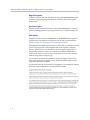
Using Multiple SoundStructure Devices With OBAM Link Interface
Each SoundStructure device has OBAM IN and OUT connectors (as shown in
the following figure) that may be used to link up to eight SoundStructure
devices1.
PIN 2: TXD
PIN 3: RXD
PIN 5: GROUND
PIN 7: CTS
PIN 8: RTS
REMOTE CONTROL 1
RS-232
C-LINK2
IN
OBAM
OUT
REMOTE CONTROL 2
IR 12V
IN
OBAM
I
OUT
To link multiple SoundStructure devices, connect the OBAM OUT port on the
first device (typically the top SoundStructure device in the equipment rack) to
the OBAM IN port on the next SoundStructure device as follows.
RS-232
C-LINK2
IN
OBAM
OUT
OUT
OUT
IR 12V
10
11
12
13
14
15
16
9
10
11
12
13
14
15
16
SoundStructureTM C16
1
2
3
4
5
6
7
8
9
10
11
12
13
14
15
16
1
2
3
4
5
6
7
8
9
10
11
12
13
14
15
16
SoundStructureTM C16
1
2
3
4
5
6
7
8
9
10
11
12
13
14
15
16
1
2
3
4
5
6
7
8
9
10
11
12
13
14
15
REMOTE CONTROL 2
16
INPUTS
OBAM
9
8
REMOTE CONTROL 1
90-250 VAC
50/60 Hz
1
IN
8
7
OUTPUTS
RS-232
C-LINK2
7
6
REMOTE CONTROL 2
IR 12V
PIN 2: TXD
PIN 3: RXD
PIN 5: GROUND
PIN 7: CTS
PIN 8: RTS
LAN
6
5
INPUTS
OBAM
5
4
REMOTE CONTROL 1
90-250 VAC
50/60 Hz
IN
4
3
OUTPUTS
RS-232
C-LINK2
3
2
REMOTE CONTROL 2
IR 12V
PIN 2: TXD
PIN 3: RXD
PIN 5: GROUND
PIN 7: CTS
PIN 8: RTS
LAN
2
1
INPUTS
90-250 VAC
50/60 Hz
LAN
1
REMOTE CONTROL 1
OUTPUTS
PIN 2: TXD
PIN 3: RXD
PIN 5: GROUND
PIN 7: CTS
PIN 8: RTS
SoundStructureTM C16
Firmware version 1.1 or higher is required for linking multiple devices.
2-9
Hardware Installation Guide for the Polycom SoundStructure C16, C12, C8, And SR12
Because the OBAM interface is bi-directional, data will flow in both directions
on the single cable between devices. Due to this bi-directionality, do not loop
the OBAM link connections (as follows).
PIN 2: TXD
PIN 3: RXD
PIN 5: GROUND
PIN 7: CTS
PIN 8: RTS
RS-232
90-250 VAC
50/60 Hz
LAN
C-LINK2
IN
OBAM
OUT
IR 12V
PIN 2: TXD
PIN 3: RXD
PIN 5: GROUND
PIN 7: CTS
PIN 8: RTS
RS-232
90-250 VAC
50/60 Hz
LAN
C-LINK2
IN
OBAM
OUT
IR 12V
PIN 2: TXD
PIN 3: RXD
PIN 5: GROUND
PIN 7: CTS
PIN 8: RTS
RS-232
90-250 VAC
50/60 Hz
LAN
C-LINK2
IN
OBAM
OUT
IR 12V
Once the devices are connected over OBAM, the SoundStructure devices will
behave as one large audio device, in other words, all the inputs from all the
SoundStructure devices are available on all the devices. Any combination of
SoundStructure C16, C12, C8, and SR12 devices may be linked together up to
a total of eight devices.
When the SoundStructure devices are connected over the OBAM Link, the
OBAM Input Status LED illuminates when there is a valid connection between
the OBAM IN port on this device and an OBAM OUT port on a second
SoundStructure device. This LED will not illuminate unless there is a valid
connection between the two devices. The OBAM Output Status LED
illuminates when there is a valid connection between the OBAM OUT port on
this device and an OBAM IN port on a different SoundStructure device. This
LED will not illuminate unless there is a valid connection between the two
devices.
A 12-inch OBAM cable is provided with each SoundStructure device. Should
longer OBAM cables be required, standard IEEE1394b "beta" cables may be
used. The maximum length of any single link between devices is 10 feet (3 m).
See OBAM Link for more details. An OBAM link cable may be tested by
inserting the same cable into the OBAM IN and OBAM OUT ports. If the
OBAM input and output status LEDs illuminate, the OBAM cable is fully
functional.
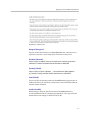
Device ID’s
When multiple devices are connected via the OBAM interface, internal
SoundStructure device ID’s are assigned automatically based on the OBAM
connections. The device that has no OBAM IN connection will be device 1. The
device connected to that unit will be device 2, and so on until the last device -
2 - 10
Installing The SoundStructure C16, C12, C8, And SR12
the device with no OBAM OUT connection. The device ID is important for
ensuring that a system is cabled properly so that it matches the configuration
that will be uploaded to the system.
As an example, consider the following figure that shows a SoundStructure C12
linked with a C8.
PHONE
LINE
PIN 2: TXD
PIN 3: RXD
PIN 5: GROUND
PIN 7: CTS
PIN 8: RTS
RS-232
LAN
C-LINK2
IN
OBAM
OUT
RS-232
C-LINK2
IN
OBAM
OUT
2
3
4
5
6
7
8
9
10
11
12
1
2
3
4
5
6
7
8
9
10
11
12
IR 12V
OUTPUTS
TM
SoundStructure C12
INPUTS
REMOTE CONTROL 2
IR 12V
PIN 2: TXD
PIN 3: RXD
PIN 5: GROUND
PIN 7: CTS
PIN 8: RTS
LAN
1
REMOTE CONTROL 1
1
2
3
4
5
6
7
8
1
2
3
4
5
6
7
8
OUTPUTS
REMOTE CONTROL 1
REMOTE CONTROL 2
TM
SoundStructure C8
INPUTS
The SoundStructure Studio software can be used to create a design that will be
uploaded into the devices. In this example, the configuration file requires
devices to be linked together with the C12 as the first device (device ID 1) and
the C8 as the second device (device ID 2). The wiring report summarizes the
cabling connections for the input and output signals. A typical wiring report
generated for the SoundStructure devices is shown in the following text.
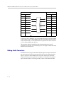
This wiring report shows the signal connections to both the SoundStructure
C12 at device ID 1, and the SoundStructure C8 at device ID 2. The report also
indicates a telephony interface is plugged into the C12 and a Polycom HDX
video codec is connected via the C-Link2 interface to the C12. This report also
summarizes how the individual inputs and outputs should be connected to
the rear-panel of the SoundStructure devices, for instance Table Mic 1 should
be connected to input 1 on the SoundStructure C12.
SoundStructure system: New SoundStructure
C12 (bus id: 1)
C-Series Mic Input
1: Table Mic 1
2: Table Mic 2
3: Table Mic 3
4: Table Mic 4
5: Table Mic 5
6: Table Mic 6
7: Table Mic 7
8: Table Mic 8
9: Table Mic 9
10: Table Mic 10
11: Table Mic 11
12: Table Mic 12
C-Series Line
1: Amplifier
2: Amplifier
3: Amplifier
Output
1 (Left)
1 (Right)
2 (Left)
2 - 11
Hardware Installation Guide for the Polycom SoundStructure C16, C12, C8, And SR12
4: Amplifier 2 (Right)
Plugin Card: Single Line Telephone
1: Phone In, Phone Out
C-Link2 Interface: Polycom HDX
C8 (bus id: 2)
C-Series Mic Input
1: Table Mic 13
2: Table Mic 14
3: Table Mic 15
4: Table Mic 16
5: Lectern Mic
6: Wireless Mic
7: Program Audio (Left)
8: Program Audio (Right)
Wiring the system as described in the wiring report and linking multiple
devices as indicated to ensure the device ID’s of the system match the
configuration file is an important step to having the system operate properly
once the configuration file is uploaded to the devices.
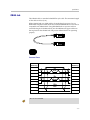
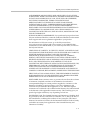
Connecting IR Port To Optional Receiver And/Or RS-232 To Control System
IR Port
The IR receiver port is compatible with IR receivers such as Xantech models
780-80, 780-90, 480-00, 480-80, and 490-00. Terminate the IR receiver into the
supplied terminal block using the pinout shown in the following figure.
Top View
1
2
3
2 - 12
Pin
Signal
1
+12 V
2
Ground
3
IR Signal Data
Installing The SoundStructure C16, C12, C8, And SR12
480-00 Series
Data
+12V
GND
1
2
3
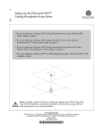
RS-232
The RS-232 interface is capable of running up to 115,200 bps and has a default
rate of 9,600 bps, eight data bits, no parity, one stop bit (8-N-1). The pinout of
the connection and the recommended straight-through cabling to a control
system is shown in the following figure.
Pin 5
Pin 9
Pin 1
Pin 6
2 - 13
Hardware Installation Guide for the Polycom SoundStructure C16, C12, C8, And SR12
SoundStructure
Control System
Pin
Signal
Pin
Signal
1
-
1
-
2
TX
2
RX
3
RX
3
TX
4
-
4
-
5
Ground
5
Ground
6
-
6
-
7
CTS
7
RTS
8
RTS
8
CTS
9
-
9
-
At rates at or above 38,400 bps, it is recommended that flow control be enabled
on the control system. The SoundStructure device will detect the use of flow
control automatically - no user adjustment is required to turn flow control on
or off on the SoundStructure devices.
The maximum length of an RS-232 cable is determined by the overall
capacitance of the cable. For practical purposes, the length of the RS-232 cable
should not exceed fifty feet.
Making Audio Connections
SoundStructure devices provide balanced audio input and output connections
that are terminated with 3.5 mm terminal blocks. For each balanced analog
input or output on the SoundStructure rear-panel, the first pin should be
connected to the positive signal, the second pin is connected to the negative
signal, and the third pin is chassis ground as shown in the balanced audio
2 - 14
Installing The SoundStructure C16, C12, C8, And SR12
connections in the following figure. To connect the SoundStructure device's
audio input and output to unbalanced audio equipment, follow the wiring in
the unbalanced audio connections below.
T
1
2
2
3
XLR Male
1
3
R S
S
XLR Female
R
T
Balanced Audio Connections
S
T
T
S
T
S
T
S
S
T
T S
S
S
T
T
Unbalanced Audio Connections
When using unbalanced audio sources or audio destinations connected to
SoundStructure devices, either wiring techniques shown previously for
connecting RCA jacks to terminal blocks may be used and both will result in
the same voltage level at the tip of the RCA jack.
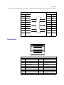
Connecting Logic Ports
There are two logic ports, called Remote Control 1 and Remote Control 2, on
the rear-panel of each SoundStructure device. Each Remote Control connector
includes eleven logic inputs, eleven logic outputs, an analog gain control
input, a +5 V supply capable of providing up to 500 mA, and a logic ground.
2 - 15
Hardware Installation Guide for the Polycom SoundStructure C16, C12, C8, And SR12
Internal to the SoundStructure device is a fuse that will trigger if the current
draw on Pin 1 exceeds 500 mA. The fuse will reset itself once the excessive
load is removed.
As there are two logic connectors, there are a total of twenty-two logic inputs,
twenty-two logic outputs, two analog gain inputs, and two +5 V supplies and
two logic grounds per SoundStructure device. The pinouts and signal
definition are shown in the following figures.
Pin 13
Pin 1
Pin 25
Pin 13
Pin 14
REMOTE CONTROL 1
Pin 25
Pin 1
Pin 14
REMOTE CONTROL 2
Remote Control 1
Pin
Signal
Pin
Signal
1
+5 V
14
Logic Input 1
2
Logic Output 1
15
Logic Input 2
3
Logic Output 2
16
Logic Input 3
4
Logic Output 3
17
Logic Input 4
5
Logic Output 4
18
Logic Input 5
6
Logic Output 5
19
Logic Input 6
7
Logic Output 6
20
Logic Input 7
8
Logic Output 7
21
Logic Input 8
9
Logic Output 8
22
Logic Input 9
10
Logic Output 9
23
Logic Input 10
11
Logic Output 10
24
Logic Input 11
12
Logic Output 11
25
Ground
13
Analog Gain 1
Remote Control 2
2 - 16
Pin
Signal
Pin
Signal
1
+5 V
14
Logic Input 12
2
Logic Output 12
15
Logic Input 13
3
Logic Output 13
16
Logic Input 14
4
Logic Output 14
17
Logic Input 15
5
Logic Output 15
18
Logic Input 16
6
Logic Output 16
19
Logic Input 17
7
Logic Output 17
20
Logic Input 18
Installing The SoundStructure C16, C12, C8, And SR12
8
Logic Output 18
21
9
Logic Output 19
22
Logic Input 19
Logic Input 20
10
Logic Output 20
23
Logic Input 21
11
Logic Output 21
24
Logic Input 22
12
Logic Output 22
25
Ground
13
Analog Gain 2
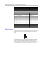
Logic Inputs
All digital logic inputs (logic inputs 1 - 22) operate as contact closures and may
either be connected to ground (closed) or not connected to ground (open). The
logic input circuitry is shown in the following figure. Chapter 4 Logic
Examples provides examples of how to use the logic input pins.
SoundStructure Logic Input
3.3V
Logic
Status
Logic Input Pin
Logic Pin 25 (Ground)
Analog Gain Input
The analog gain inputs (analog gain 1 and 2) operate by measuring an analog
voltage between the analog input pin and the ground pin. The maximum input
voltage level should not exceed +6 V. It is recommended that the +5 V supply
on Pin 1 be used as the upper voltage limit.
The following figure shows the analog gain input pin and the associated +5 V
and ground pins that are used with the analog gain input pin. The analog
voltage on the analog gain input pin is converted to a digital value via an 8-bit
analog-to-digital converter for use within the SoundStructure devices. The
maximum voltage value, i.e., 0 dBFS on the analog gain input, is 4.096 V. The
SoundStructure API commands analog_gpio_min and analog_pio_max are
used to map the values into a desired range of numerical values. By default 0
V is converted to 0 and 4.096 V and above is converted to 255.
2 - 17
Hardware Installation Guide for the Polycom SoundStructure C16, C12, C8, And SR12
Chapter 4 Logic Examples provides an example of how to use the analog gain
input pin.
SoundStructure Logic Input
5V
Analog
Voltage
Value
Logic Pin 1 (+5V)
Analog Gain Input Pin
Logic Pin 25 (Ground)
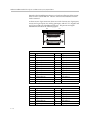
Logic Outputs
All logic outputs are configured as open-collector circuits and may be used
with external voltage sources. The maximum voltage that should be used with
the logic outputs is 60 V with a maximum current of 500 mA.
SoundStructure Logic Output
Logic Output Pin
Logic
Controller
Chassis
Ground
The open collector design is shown in the following figure and works as a
switch as follows: when the logic output pin is set high (on), the transistor will
turn on and the signal connected to the logic output pin will be grounded and
current will flow from the logic output pin to chassis ground.
2 - 18
Installing The SoundStructure C16, C12, C8, And SR12
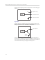
When the logic output is set low (off), the transistor will turn off and an open
circuit will be created between the logic output and the chassis ground
preventing any flow of current as shown in the following figure.
Logic Output Pin
Logic Output
High (On)
Chassis Ground
Logic Output Pin
Logic Output
Low (Off)
Chassis Ground
See Logic Examples for information on how to wire the logic interface for
common logic applications.
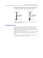
Powering Up The System
Connect the AC power line to a grounded AC power main when ready to
power the device and plug the other end securely into the rear of the
SoundStructure unit. Ensure the plug is securely inserted as shown in the
following figure. Upon insertion there will be some initial resistance - continue
pushing until the power cord is plugged in.
The SoundStructure units require an AC voltage supply in the range of 90-250
VAC and 50-60 Hz. Power should be applied after any plug-in cards are
installed.
As there is no power switch on the SoundStructure devices, once power is
connected, the system will begin the boot-up process.
2 - 19
Hardware Installation Guide for the Polycom SoundStructure C16, C12, C8, And SR12
For more information, see Front-Panel LED Interpretation.
Power cord plugged in
Power cord not plugged in
Configuring The SoundStructure Devices
For information on configuring software for the SoundStructure, see the
manual entitled Design Guide for the Polycom SoundStructure C16, C12, C8,
and SR12.
2 - 20
3
Specifications
Technical Specifications
Dimensions
•
19" (483 mm) W x 13.5" (343 mm) L x 1.75" (45 mm) H (one rack unit)
Weight
•
12 lbs. (5.5 kg) dry, 14 lbs. (6.4 kg) shipping
Connectors
•
RS-232: DB9F
•
OBAM In/Out: IEEE 1394B
•
CLINK2: RJ45
•
LAN: RJ45
•
Control/Status: DB25F
•
Audio: Mini (3.5 mm) quick connect terminal blocks
•
IR Receive: Mini (3.5 mm) quick connect terminal block
Power
•
Internal power supply
•
Input voltage of 90-250 VAC; 50-60 Hz
•
Line power requirements (including 0.6 PF): 130 VA (C16), 115 VA (C12),
105 VA (SR12), 95 VA (C8)
3-1
Hardware Installation Guide for the Polycom SoundStructure C16, C12, C8, and SR12
Thermal
•
Thermal Dissipation (Btu/hr): 266 Btu/hr (C16), 230 Btu/hr (C12), 215
Btu/hr (SR12), 200 Btu/hr (C8)
•
Operating temperature 0 - 40° C (104° F)
Inputs
•
Phantom power: 48 V DC through 6.8 kOhm series resistor per leg, 7.5 mA
per channel, software selectable
•
Analog input gain: -20 to 64 dB on all inputs in 0.5 dB steps, software
adjustable
•
Maximum input amplitude: +20.4 dBu, 1% THD + N
•
Nominal level: 0 dBu (0.775 Vrms)
•
Equivalent input noise: <-122 dBu, 20-20,000 Hz, Rs=150 Ohms (1%)
•
Input impedance: 10 kOhms
•
Input EMI Filter: Pi filter on all audio inputs
Outputs
•
Output gain: -100 to 20 dB in 1 dB steps, software adjustable
•
Maximum output amplitude: +23 dBu, 1% THD + N
•
Nominal output level: 0 dBu (0.775 Vrms)
•
Output impedance: 50 Ohm, each leg to ground, designed to drive loads >
600 Ohms
•
Output EMI filter: Pi filter on all audio outputs
System
Unless noted, all values are valid for all channels at 0 dB input gain.
Warning
3-2
•
Frequency response: 20-22,000 Hz, + 0.1 /- 0.3 dB
•
Idle channel noise: <-109 dB FS no weighting, 20-20,000 Hz, -60dB FS, 997
Hz input signal, 0 dB gain
•
Dynamic range: >109 dB FS no weighting, 20 - 20,000 Hz, -60 dB FS, 997
Hz input signal, 0 dB gain
•
Linearity: 0 dB FS to -122 dB FS +/- 1 dB
Specifications
•
THD+N: < 0.005%, -20 dB FS input signal
•
Common mode rejection ratio: <-61 dB, 20-20,000 Hz, no weighting
•
Cross talk: <-110 dB, 20-20,000 Hz, 1kHz, channel-to-channel
•
Latency: Mic/Line inputs to outputs: 20 ms, AEC and NC processing
enabled
•
Acoustic echo cancellation span: 200 ms
•
Total cancellation: >65 dB
•
Convergence rate: 40 dB/second
•
Noise cancellation: 0-20 dB, software selectable
•
Control inputs: contact closure
•
Status outputs: open collector 60 V and 500 mA maximum total per
outputs
•
All signal ground pins connected to chassis ground through low
impedance planes
Telco
•
Input gain: -100 to +20 dB in 1 dB steps, software adjustable
•
Nominal transmit level: 0 dBu in SoundStructure device yields -15 to -17
dBm to phone (country code dependent)
•
Off hook loop current: 10 mA (minimum) to 120 mA (maximum)
•
Output gain: -100 to +20 dB in 1 dB steps, software adjustable
•
Frequency response: 250-3300 Hz
•
Dynamic range: >70 dB FS, 250-3300 Hz, "A" weighted
3-3
Hardware Installation Guide for the Polycom SoundStructure C16, C12, C8, and SR12
Pin Out Summary
Warning
Drawings and part numbers are provided for reference only. Other than cables
provided by Polycom, Polycom claims no responsibility or liability for the quality,
performance, or reliability of cables based on these reference drawings. Contact a
Polycom reseller to order cables that meet the appropriate manufacturing
tolerances, quality, and performance parameters for particular applications.
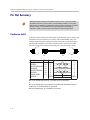
Conference Link2
To build a custom Conference Link2 cable, use shielded CAT5e, or better, and
terminate both end connectors, P1 and P2, with standard 8P8C plugs (for
example, RJ45) using the wiring connections shown in the following figure.
The maximum length for this cable is 100 feet (30 m). Note that this cable
provides a cross-over connection between pins 1 and 2 and pins 5 and 6.
8
1
1
P1
P2
AWG P1
COLOR
24
WHITE/GREEN
1
24
GREEN
2
WHITE/ORANGE 24
5
24
ORANGE
6
24
WHITE/BROWN
7
24
BROWN
8
24
DRAIN WIRE
3
SHIELD
SHELL
8
P2
5
6
1
2
7
8
3
SHELL
P1 - RJ-45 shielded Keystone jack, L-com RJ110C5-S or equivalent,
or
P1 - RJ-45 shielded plug, Tyco 5-569552 or equivalent with shielded RJ-45 panel
coupler kit (L-com ECF504-SC5E or equivalent).
P2- RJ-45 shielded plug, Tyco 5-569552 or equivalent.
3-4
Specifications
OBAM Link
The OBAM cable is a standard 1394b BETA style cable. The maximum length
of this cable is 10 feet (3 m).
While OBAM Link uses 1394b cables, the underlying bus protocol is not
IEEE1394b compliant which means that external IEE1394b devices will not be
compatible with OBAM Link. Using IEE1394b hubs or repeaters will not
extend the length of OBAM and any non-SoundStructure approved device
that is placed on the OBAM Link will prevent OBAM Link from operating
properly.
Connector Pinout
1394b
BETA Plug
1
2
1394b
BETA Plug
Red
Green
9
3
4
5
6
8
SHELL
3
4
5
Blue
Orange
White
Black
1
2
9
6
8
SHELL
Pin 7 is not connected.
Warning
3-5
Hardware Installation Guide for the Polycom SoundStructure C16, C12, C8, and SR12
IR Receiver
The IR receiver port on the rear-panel of a SoundStructure device is shown in
the following figure.
PIN 2: TXD
PIN 3: RXD
PIN 5: GRO
PIN 7: CTS
PIN 8: RTS
OUT
IR 12V
The IR receiver port accepts a standard 3.5 mm terminal block which should
be terminated to the IR receiver as shown in the following figures.
Top View
1
2
3
Pin
Signal
1
+12 V
2
Ground
3
IR Signal Data
RS-232
The RS-232 interface requires a straight-through cabling to a control system as
shown in the following figures.
Pin 5
Pin 9
3-6
Pin 1
Pin 6
Specifications
SoundStructure
Control System
Pin
Signal
Pin
Signal
1
-
1
-
2
TX
2
RX
3
RX
3
TX
4
-
4
-
5
Ground
5
Ground
6
-
6
-
7
CTS
7
RTS
8
RTS
8
CTS
9
-
9
-
Logic Interface
Pin 13
Pin 1
Pin 25
Pin 13
Pin 14
REMOTE CONTROL 1
Pin 25
Pin 1
Pin 14
REMOTE CONTROL 2
Remote Control 1
Pin
Signal
Pin
Signal
1
+5 V
14
Logic Input 1
2
Logic Output 1
15
Logic Input 2
3
Logic Output 2
16
Logic Input 3
4
Logic Output 3
17
Logic Input 4
5
Logic Output 4
18
Logic Input 5
6
Logic Output 5
19
Logic Input 6
7
Logic Output 6
20
Logic Input 7
8
Logic Output 7
21
Logic Input 8
9
Logic Output 8
22
Logic Input 9
10
Logic Output 9
23
Logic Input 10
3-7
Hardware Installation Guide for the Polycom SoundStructure C16, C12, C8, and SR12
11
Logic Output 10
24
Logic Input 11
12
Logic Output 11
25
Ground
13
Analog Gain 1
Remote Control 2
Pin
Signal
Pin
Signal
1
+5 V
14
Logic Input 12
2
Logic Output 12
15
Logic Input 13
3
Logic Output 13
16
Logic Input 14
4
Logic Output 14
17
Logic Input 15
5
Logic Output 15
18
Logic Input 16
6
Logic Output 16
19
Logic Input 17
7
Logic Output 17
20
Logic Input 18
8
Logic Output 18
21
Logic Input 19
9
Logic Output 19
22
Logic Input 20
10
Logic Output 20
23
Logic Input 21
11
Logic Output 21
24
Logic Input 22
12
Logic Output 22
25
Ground
13
Analog Gain 2
Audio Connections
SoundStructure devices provide balanced audio input and output connections
that are terminated with 3.5 mm terminal blocks as shown in the following
figure.
1
For each balanced analog input or output on the SoundStructure rear-panel,
the first pin should be connected to the positive signal, the second pin is
connected to the negative signal, and the third pin is chassis ground as shown
in the balanced audio connections in the following figure. To connect the
3-8
Specifications
SoundStructure device's audio input and output to other balanced or
unbalanced audio equipment, follow the wiring convention in the unbalanced
audio connections following figure.
T
1
2
2
3
XLR Male
1
3
R
S
S
XLR Female
R
T
Balanced Audio Connections
S
T
T
S
T
S
T
S
S
T
T
S
S
S
T
T
Unbalanced Audio Connections
3-9
Hardware Installation Guide for the Polycom SoundStructure C16, C12, C8, and SR12
3 - 10
4
Logic Examples
Logic Input
Contact Closure
Pin 14 : Logic Input 1
Pin 25 : Ground
Remote Control
When the contact is closed, the logic input pin (Pin 14 in this example) is driven
low (off). When the switch is open, the logic input pin will float high (on).
Typical applications may be push to mute or push to talk buttons or room
combining for changing the device settings based on the room configuration.
4-1
Hardware Installation Guide for the Polycom SoundStructure C16, C12, C8, and SR12
Logic Output
SoundStructure Powered Relay
5 V Relay
Pin 1 : +5 V
External
Device to
be
Controlled
Pin 2 : Logic Output 1
Remote Control
Relays rated for +5 V or lower may be driven directly from the +5 V logic
connector pin 1 supply. Relays rated for more than +5 V will need an external
power supply as described in the next example.
When the logic output (Pin 2 in this example) is set on (high), current flows
from Pin 2 to ground and current that flows will energize the relay coil and
close the relay contact. When the logic output is set off (low), current will stop
flowing to the relay coil, causing the relay contact to open. A diode is
recommended to be placed in parallel with the relay to provide a path for the
discharge current of the magnetic coil of the relay. This current will discharge
over a very short period of time and a diode capable of handling a large
amount of surge current such as the IN4001 is recommended and is available
from several manufacturers.
This example circuit uses an Omron G5CA relay and the coil resistance is 125
ohms. Because of this coil resistance, an additional series resistor is not
required to limit the current from the 5 V supply to less than 500 mA in this
example.
Externally Powered Relay
External +12 V
Pin 25 : Ground
- +
12 V Relay
Pin 2 : Logic Output 1
Remote Control
External
Device to
be
Controlled
SoundStructure can be used with externally powered relays when the
following conditions exist:
4-2
•
The relay is DC powered.
•
The DC voltage does not exceed 60 V.
Logic Examples
•
The current from the power supply and relay circuit does not exceed 500
mA.
As with the 5 V relay example, when the logic output pin (Pin 2 in this
example) is set on (high), the relay energizes and the relay contact is closed.
When the logic output in is set off (low), current stops flowing, and the relay
de-energizes and the relay contact is opened.
A diode is recommended to be placed in parallel with the relay to provide a
path for the discharge of the magnetic coil of the relay. This current will
discharge over a very short period of time and a diode capable of handling a
large amount of surge current such as the IN4001 is recommended and is
available from several manufacturers. The IN4001 is rated up to 50 V, if higher
voltages are required, the IN4002 is rated to 100 V.
This circuit uses an Omron G7L 12 V relay with a coil resistance of 75 ohms.
For this reason, an additional series resistor between the power supply and
relay is not needed to ensure the current from the 5 V supply is less than 500
mA.
The ground connection of the power supply must be connected to the ground
pin of the logic connector (Pin 25) in order for the return currents from the
external power supply to be able to return to their source.
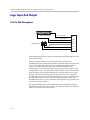
Driving An LED
Pin 1 : +5V
Pin 2 : Logic Output 1
274 ohm
Remote Control
LED
SoundStructure logic outputs can be used to turn on or off LEDs. In this
example when the logic output is driven high (on), current will flow, and the
LED will turn on. When the logic output is set low (off), current will stop
flowing, and the LED will turn off.
Most standard LEDs need about 2.0 V to illuminate. In this example a 274 ohm
resistor is used to limit the current from Pin 1.
A series resistor must be used to limit the voltage and current to a safe level for
the LED.
Increasing the series resistor value will decrease the current through the circuit
and will also decrease the voltage at the input to the LED, reducing the
brightness of the LED.
4-3
Hardware Installation Guide for the Polycom SoundStructure C16, C12, C8, and SR12
Logic Input And Output
Push To Talk Microphones
Remote Control
Pin 14 : Logic Input 1
Pin 2 : Logic Output 1
Pin 25 : Ground
Analog Input
White
Orange
Green
Shield
Black
Red
The SoundStructure devices may be used with push to talk microphones such
as the Shure MX392.
When the orange (LED in) wire is connected to ground due to the
SoundStructure logic output being turned on, the LED on the microphone will
turn on. The LED is powered from the SoundStructure phantom power
supply on the red and black cables. This means that the LED on the
microphone does not need external power through a pull-up resistor on the
orange (LED in) wire. The shield of the cable provides a ground for the entire
audio and logic circuit even though there is a separate green wire for Logic
Ground. This means that the green wire does not need to be connected to
SoundStructure device. One could connect the green wire to the shield at the
mic side and then only need to run a 4-conductor cable plus shield to the
SoundStructure device, or one could run the microphone's logic ground to the
ground on the logic connector.
No current-limiting resistors are needed between the microphone and the
SoundStructure device as the current on the Orange (LED IN) wire when the
LED is on is on the order of microamps.
4-4
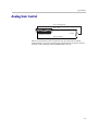
Logic Examples
Analog Gain Control
Pin 13 : Analog Input
Pin 1 : +5V
10K ohm
Remote Control
Pin 25 : Ground
Pin 13 on each Remote control connector may be used with an analog
potentiometer to provide an analog input signal that can be used to control
volume or other settings within SoundStructure devices.
4-5
Hardware Installation Guide for the Polycom SoundStructure C16, C12, C8, and SR12
4-6
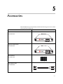
5
Accessories
The SoundStructure product family includes the following accessories, which
can be purchased separately.
Single-Line PSTN Interface
2200-35003-001
PHONE
LINE
LINE 2
LINE 1
Dual-Line PTSN interface
2200-35004-001
Terminal Blocks
2215-80031-001
Audio Adapter Cable
2457-23492-001
5-1
Hardware Installation Guide for the Polycom SoundStructure C16, C12, C8 and SR12
5-2
6
Regulatory Notices And Warranty
Information
Regulatory Notices
USA And Canada
Pt 15 Rules
This device complies with part 15 of the FCC Rules. Operation is subject to the
following two conditions: This device may not cause harmful interference, and
this device must accept any interference received, including interference that
may cause undesired operation.
Class A Digital Device Or Peripheral
NOTE: This equipment has been tested and found to comply with the limits
for a Class A digital device, pursuant to part 15 of the FCC Rules. These limits
are designed to provide reasonable protection against harmful interference
when the equipment is operated in a commercial environment. This
equipment generates, uses, and can radiate radio frequency energy and, if not
installed and used in accordance with the instruction manual, may cause
harmful interference to radio communications. Operation of this equipment
in a residential area is likely to cause harmful interference in which case the
user will be required to correct the interference at his own expense.
Modifications
In accordance with part 15 of the FCC rules, the user is cautioned that any
changes or modifications not expressly approved by Polycom Inc. could void
the user’s authority to operate the equipment.
6-1
Hardware Installation Guide for the Polycom SoundStructure C16, C12, C8, and SR12
Exhibit J - Customer Information
This equipment complies with Part 68 of the FCC rules and the requirements
adopted by the ACTA. On the exterior of the cabinet of this equipment is a
label that contains, among other information, a product identifier in the format
2HWTE01BSSTRUCTURE. If requested, this number must be provided to the
telephone company.
•
ACTA Registration Number: 2HWTE01BSSTRUCT
•
Ringer Equivalence Number (REN): 0.1B
•
Facility Interface Code (FIC): 02LS2
•
Service Order Code (SOC): 9.0Y
•
USOC Jack Type: RJ11C
A FCC compliant telephone cord and modular plug is provided with this
equipment. This equipment is designed to be connected to the telephone
network or premises wiring using a compatible modular jack that is Part 68
compliant. See Installation Instructions for details.
The REN is used to determine the quantity of devices that may be connected
to the telephone line. Excessive RENs on the telephone line may result in the
devices not ringing in response to an incoming call. Typically, the sum of
RENs should not exceed five (5.0). To be certain of the number of devices that
may be connected to a line (as determined by the total RENs) contact the local
telephone company.
If this equipment, Polycom SoundStructure TEL 1 and SoundStructure TEL 2
causes harm to the telephone network, the telephone company will notify you
in advance that temporary discontinuance of service may be required. But if
advance notice isn't practical, the telephone company will notify the customer
as soon as possible. Also, you will be advised of your right to file a complaint
with the FCC if you believe it is necessary.
The telephone company may make changes to its facilities, equipment,
operations or procedures that could affect the operation of the equipment. If
this happens the telephone company will provide advance notice so you can
make the necessary modifications to maintain uninterrupted service.
If trouble is experienced with this equipment, Polycom SoundStructure TEL 1
and SoundStructure TEL 2, for repair or warranty information, please contact
Polycom Inc., 4750 Willow Road, Pleasanton, CA 94588-2708 USA
408.526.9000. If the equipment is causing harm to the telephone network, the
telephone company may request that you disconnect the equipment until the
problem is resolved.
Connection to party line service is subject to state tariffs. (Contact the state
public utility commission, public service commission or corporation
commission for information.)
6-2
Regulatory Notices And Warranty Information
Data Equipment
The table below shows which jacks are associated with which modes of
operation:
Mode of Operation
USOC Jack
Permissive
RJ11C
Automatic Dialing
WHEN PROGRAMMING EMERGENCY NUMBERS AND/OR MAKING
TEST CALLS TO EMERGENCY NUMBERS;
•
Remain on the line and briefly explain to the dispatcher the reason for the
call.
•
Perform such activities in the off-peak hours, such as early morning or late
evening.
Canada
Canadian EMC Class A
English Statement:
This Class [A] digital apparatus complies with Canadian ICES-003.
French Statement:
Cet appareil numérique de la classe [A] est conforme à la norme NMB-003 du
Canada.
This product meets the applicable Industry Canada technical specifications.
The Ringer Equivalence Number (REN) assigned to each relevant terminal
device provides an indication of the maximum number of terminals allowed
to be connected to a telephone interface. The termination on an interface may
consist of any combination of devices subject only to the requirement that the
sum of the Ringer Equivalence Numbers of all the devices does not exceed 5.
The REN of this equipment is either marked on the unit or included in the new
style USA (FCC registration number). In the case that the REN is included in
the FCC number the user should use the flowing key to determine the value:
The FCC number is formatted as US: AAAEQ##TXXX.
## is the Ringer Equivalence Number without a decimal point (e.g. REN of 1.0
= 10, REN of 0.3 = 03). In the case of a “Z” ringer, ZZ shall appear. In the case
of approved equipment without a network interface and equipment not
connecting to circuits with analog ringing supplied then “NA” shall appear.
6-3
Hardware Installation Guide for the Polycom SoundStructure C16, C12, C8, and SR12
EEA (European Economic Area) Including Switzerland
CE Mark R & TTE Directive
This SoundStructure has been marked with the CE mark. This mark indicates
compliance with EEC Directives 89/336/EEC, 73/23/EEC 1999/5/EC. A full
copy of the Declaration of Conformity can be obtained from Polycom Ltd, 270
Bath Road, Slough, Berkshire, SL1 4DX, UK.
Česky [Czech]:
Polycom (UK) Ltd tímto prohlašuje, _e tento SoundStructure je ve shodě se
základními po_adavky a dalšími příslušnými ustanoveními směrnice
1999/5/ES.
Dansk [Danish]:
Undertegnede Polycom (UK) Ltd erklærer herved, at følgende udstyr
SoundStructure overholder de væsentlige krav og øvrige relevante krav i
direktiv 1999/5/EF.
Deutsch [German]:
Hiermit erklärt Polycom (UK) Ltd, dass sich das Gerät SoundStructure in
Übereinstimmung mit den grundlegenden Anforderungen und den übrigen
einschlägigen Bestimmungen der Richtlinie 1999/5/EG befindet.
Eesti [Estonian]:
Käesolevaga kinnitab Polycom (UK) Ltd seadme SoundStructure vastavust
direktiivi 1999/5/EÜ põhinõuetele ja nimetatud direktiivist tulenevatele
teistele asjakohastele sätetele.
English:
Hereby, Polycom (UK) Ltd. declares that this SoundStructure is in compliance
with the essential requirements and other relevant provisions of Directive
1999/5/EC.
Español [Spanish]:
Por medio de la presente Polycom (UK) Ltd declara que el SoundStructure
cumple con los requisitos esenciales y cualesquiera otras disposiciones
aplicables o exigibles de la Directiva 1999/5/CE.
6-4
Regulatory Notices And Warranty Information
Ελληνική [Greek]:
ΜΕ ΤΗΝ ΠΑΡΟΥΣΑ Polycom (UK) Ltd ΔΗΛΩΝΕΙ ΟΤΙ SoundStructure
ΣΥΜΜΟΡΦΩΝΕΤΑΙ ΠΡΟΣ ΤΙΣ ΟΥΣΙΩΔΕΙΣ ΑΠΑΙΤΗΣΕΙΣ ΚΑΙ ΤΙΣ ΛΟΙΠΕΣ
ΣΧΕΤΙΚΕΣ ΔΙΑΤΑΞΕΙΣ ΤΗΣ ΟΔΗΓΙΑΣ 1999/5/ΕΚ.
Français [French]:
Par la présente Polycom (UK) Ltd déclare que l'appareil SoundStructure est
conforme aux exigences essentielles et aux autres dispositions pertinentes de
la directive 1999/5/CE.
Italiano [Italian]:
Con la presente Polycom (UK) Ltd dichiara che questo SoundStructure è
conformeai requisiti essenzi ali ed alle altre disposizioni pertinenti stabilite
dalla direttiva 1999/5/CE.
Íslenska (Icelandic):
Hér með lýsir Polycom (UK) Ltd yfir því að SoundStructure er í samræmi við
grunnkröfur og aðrar kröfur, sem gerðar eru í tilskipun 1999/5/EC
Latviski [Latvian]:
Ar šo Polycom (UK) Ltd deklarē, ka SoundStructure atbilst Direktīvas
1999/5/EK būtiskajām prasībām un citiem ar to saistītajiem noteikumiem.
Lietuvių [Lithuanian]:
Šiuo Polycom (UK) Ltd deklaruoja, kad šis SoundStructure atitinka esminius
reikalavimus ir kitas 1999/5/EB Direktyvos nuostatas.
Nederlands [Dutch]:
Hierbij verklaart Polycom (UK) Ltd dat het toestel SoundStructure in
overeenstemming is met de essentiële eisen en de andere relevante bepalingen
van richtlijn 1999/5/EG.
Malti [Maltese]:
Hawnhekk, Polycom (UK) Ltd, jiddikjara li dan [SoundStructure] jikkonforma
mal-htigijiet essenzjali u ma provvedimenti ohrajn relevanti li hemm
fid-Dirrettiva 1999/5/EC.
6-5
Hardware Installation Guide for the Polycom SoundStructure C16, C12, C8, and SR12
Magyar [Hungarian]:
Alulírott, Polycom (UK) Ltd nyilatkozom, hogy a SoundStructure megfelel a
vonatkozó alapvetõ követelményeknek és az 1999/5/EC irányelv egyéb
elõírásainak.
Norsk [Norwegian]:
Polycom (UK) Ltd erklærer herved at utstyret SoundStructure er i samsvar
med de grunnleggende krav og øvrige relevante krav i direktiv 1999/5/EF.
Polski [Polish]:
Niniejszym Polycom (UK) Ltd oświadcza, że SoundStructure jest zgodne z
zasadniczymi wymaganiami oraz innymi stosownymi postanowieniami.
Polish Center for Testing and Certification Notice
The equipment should draw power from a socket with an attached protection
circuit (a 3-prong socket). All equipment that works together (computer,
monitor, printer, and so on) should have the same power supply source.
The phasing conductor of the room's electrical installation should have a
reserve short-circuit protection device in the form of a fuse with a nominal
value no larger than 16 amperes (A).
To completely switch off the equipment, the power supply cable must be
removed from the power supply socket, which should be located near the
equipment and easily accessible.
A protection mark "B" confirms that the equipment is in compliance with the
protection usage requirements of standard PN-EN 55022.
6-6
Regulatory Notices And Warranty Information
Dyrektywy 1999/5/WE.
Português [Portuguese]:
Polycom (UK) Ltd declara que este SoundStructure está conforme com os
requisitos essenciais e outras disposições da Directiva 1999/5/CE.
Slovensko [Slovenian]:
Polycom (UK) Ltd izjavlja, da je ta SoundStructure v skladu z bistvenimi
zahtevami in ostalimi relevantnimi določili direktive 1999/5/ES.
Slovensky [Slovak]:
Polycom (UK) Ltd týmto vyhlasuje, _e SoundStructure spĺňa základné
po_iadavky a všetky príslušné ustanovenia Smernice 1999/5/ES.
Suomi [Finnish]:
Polycom (UK) Ltd vakuuttaa täten että SoundStructure tyyppinen laite on
direktiivin 1999/5/EY oleellisten vaatimusten ja sitä koskevien direktiivin
muiden ehtojen mukainen.
Svenska [Swedish]:
Härmed intygar Polycom (UK) Ltd att denna SoundStructure står I
överensstämmelse med de väsentliga egenskapskrav och övriga relevanta
bestämmelser som framgår av direktiv 1999/5/EG.
6-7
Hardware Installation Guide for the Polycom SoundStructure C16, C12, C8, and SR12
EU Czech republic
Australia
Mains powered POT’s Voice Telephony without Emergency 000 dialing
Warning
This equipment will be inoperable when mains power fails
Reference: AS/ACIF S002:2001 (incorporating Amdt 1) DECEMBER 2001
Clause 5.1.8.4 Provision of power-fail advice
Japan (VCCI)
Class A ITE
6-8
Regulatory Notices And Warranty Information
Korea
Class A
Rest Of World
EMC. CLASS A ITE
WARNING
This is a Class A product. In a domestic environment this product may cause
radio interference in which case the user may be required to take adequate
measures.
Installation Instructions*
Installation must be performed in accordance with all relevant national wiring
rules
Plug acts as Disconnect Device*
The socket outlet to which this apparatus is connected must be installed near
the equipment and must always be readily accessible
6-9
Hardware Installation Guide for the Polycom SoundStructure C16, C12, C8, and SR12
Warranty Information
LIMITED WARRANTY
Polycom warrants to the end user ("Customer") that the product will be free
from defects in workmanship and materials, under normal use and service, for
one year, or such longer period as Polycom may announce publicly from time
to time for particular products, from the date of purchase from Polycom or its
authorized reseller.
Polycom's sole obligation under this express warranty shall be, at Polycom's
option and expense, to repair the defective product or part, deliver to
Customer an equivalent product or part to replace the defective item, or if
neither of the two foregoing options is reasonably available, Polycom may, in
its sole discretion, refund to Customer the purchase price paid for the defective
product. All products that are replaced will become the property of Polycom.
Replacement products or parts may be new or reconditioned. Polycom
warrants any replaced or repaired product or part for ninety (90) days from
shipment, or the remainder of the initial warranty period, whichever is longer.
Products returned to Polycom must be sent prepaid and packaged
appropriately for safe shipment and it is recommended that they be insured or
sent by a method that provides for tracking of the package. Responsibility for
loss or damage does not transfer to Polycom until the returned item is received
by Polycom. The repaired or replaced item will be shipped to Customer, at
Polycom's expense, not later than thirty (30) days after Polycom receives the
defective product, and Polycom will retain risk of loss or damage until the
item is delivered to Customer.
EXCLUSIONS. POLYCOM WILL NOT BE LIABLE UNDER THIS LIMITED
WARRANTY IF ITS TESTING AND EXAMINATION DISCLOSE THAT THE
ALLEGED DEFECT OR MALFUNCTION IN THE PRODUCT DOES NOT
EXIST OR RESULTS FROM:
•
FAILURE TO FOLLOW POLYCOM'S INSTALLATION, OPERATION,
OR MAINTENANCE INSTRUCTIONS.
•
UNAUTHORIZED PRODUCT MODIFICATION OR ALTERATION.
•
UNAUTHORIZED USE OF COMMON CARRIER COMMUNICATION
SERVICES ACCESSED THROUGH THE PRODUCT.
•
ABUSE, MISUSE, NEGLIGENT ACTS OR OMISSIONS OF CUSTOMER
AND PERSONS UNDER CUSTOMER'S CONTROL; OR
•
ACTS OF THIRD PARTIES, ACTS OF GOD, ACCIDENT, FIRE,
LIGHTING, POWER SURGES OR OUTAGES, OR OTHER HAZARDS.
WARRANTY EXCLUSIVE. IF A POLYCOM PRODUCT DOES NOT
OPERATE AS WARRANTED ABOVE, CUSTOMER'S SOLE REMEDY FOR
BREACH OF THAT WARRANTY SHALL BE REPAIR, REPLACEMENT, OR
REFUND OF THE PURCHASE PRICE PAID, AT POLYCOM'S OPTION. TO
THE FULL EXTENT ALLOWED BY LAW, THE FOREGOING WARRANTIES
6 - 10
Regulatory Notices And Warranty Information
AND REMEDIES ARE EXCLUSIVE AND ARE IN LIEU OF ALL OTHER
WARRANTIES, TERMS, OR CONDITIONS, EXPRESS OR IMPLIED, EITHER
IN FACT OR BY OPERATION OF LAW, STATUTORY OR OTHERWISE,
INCLUDING WARRANTIES, TERMS, OR CONDITIONS OF
MERCHANTABILITY, FITNESS FOR A PARTICULAR PURPOSE,
SATISFACTORY QUALITY, CORRESPONDENCE WITH DESCRIPTION,
AND NON-INFRINGEMENT, ALL OF WHICH ARE EXPRESSLY
DISCLAIMED. POLYCOM NEITHER ASSUMES NOR AUTHORIZES ANY
OTHER PERSON TO ASSUME FOR IT ANY OTHER LIABILITY IN
CONNECTION WITH THE SALE, INSTALLATION, MAINTENANCE OR
USE OF ITS PRODUCTS.
SUPPORT & SERVICE AGREEMENTS. If you purchased your product from a
Polycom Authorized Reseller, contact the Authorized Reseller for information
about support and service agreements applicable to your product.
For information on Polycom service, go to the Polycom web site
www.polycom.com, products and services menu, or call 1-800-765-9266,
outside the US call 1-408-526-9000, or your local Polycom Office, as listed on
the Polycom Web site.
LIMITATION OF LIABILITY. TO THE FULL EXTENT ALLOWED BY LAW,
POLYCOM EXCLUDES FOR ITSELF AND ITS SUPPLIERS ANY LIABILITY,
WHETHER BASED IN CONTRACT OR TORT (INCLUDING
NEGLIGENCE), FOR INCIDENTAL, CONSEQUENTIAL, INDIRECT,
SPECIAL, OR PUNITIVE DAMAGES OF ANY KIND, OR FOR LOSS OF
REVENUE OR PROFITS, LOSS OF BUSINESS, LOSS OF INFORMATION OR
DATA, OR OTHER FINANCIAL LOSS ARISING OUT OF OR IN
CONNECTION WITH THE SALE, INSTALLATION, MAINTENANCE, USE,
PERFORMANCE, FAILURE, OR INTERRUPTION OF ITS PRODUCTS,
EVEN IF POLYCOM OR ITS AUTHORIZED RESELLER HAS BEEN
ADVISED OF THE POSSIBILITY OF SUCH DAMAGES, AND LIMITS ITS
LIABILITY TO REPAIR, REPLACEMENT, OR REFUND OF THE PURCHASE
PRICE PAID, AT POLYCOM'S OPTION. THIS DISCLAIMER OF LIABILITY
FOR DAMAGES WILL NOT BE AFFECTED IF ANY REMEDY PROVIDED
HEREIN SHALL FAIL OF ITS ESSENTIAL PURPOSE.
DISCLAIMER. Some countries, states, or provinces do not allow the exclusion
or limitation of implied warranties or the limitation of incidental or
consequential damages for certain products supplied to consumers, or the
limitation of liability for personal injury, so the above limitations and
exclusions may be limited in their application to you. When the implied
warranties are not allowed to be excluded in their entirety, they will be limited
to the duration of the applicable written warranty. This warranty gives you
specific legal rights which may vary depending on local law.
GOVERNING LAW. This Limited Warranty and Limitation of Liability shall
be governed by the laws of the State of California, U.S.A., and by the laws of
the United States, excluding their conflicts of laws principles. The United
Nations Convention on Contracts for the International Sale of Goods is hereby
excluded in its entirety from application to this Limited Warranty and
Limitation of Liability.
6 - 11
Hardware Installation Guide for the Polycom SoundStructure C16, C12, C8, and SR12
6 - 12