1
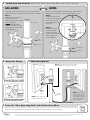
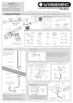
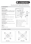
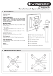
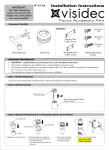
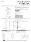
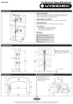
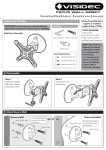
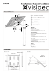
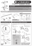
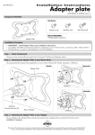
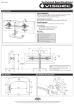
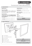
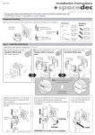
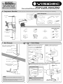
IMPORTANT:
The “User Operating
Card” must be left
with Visidec Focus
Micro once installed
Installation Instructions
A Component Checklist - Check you have received all parts against the component checklist prior to installing
Desk Clamp Box
5mm Allen
Key
Top
5mm Allen
Key
Desk Clamp Bracket
Pressure Plate
M8 Desk
Clamp Screw
Bits Box
Display Mounting
Screws
User
Operating
Card
(See note at top
of page)
2mm Allen
Key
Cable Balls
(x2)
M8x30mm
Screw
M4x10mm
(x4)
M4x12mm
(x4)
Pole Assembly
Bolt Through
Base
Bottom
B1
OR
Bolt Through
Drill a 9mm (³/8”) hole in the work
surface at the desired position and
assemble as shown below.
Bottom
Bolt Through Base
B2
Desk Clamp
Step 1: Attach the Desk Clamp Bracket
to the bottom of the Pole Assembly using
the M8x30mm Screw. Tighten firmly
using the 5mm Allen Key. Ensure the
Visidec logo is facing the front as shown.
Slot
Pole Assembly
Steel Washer
Cable Clip
Desk
Clamp
Bracket
Bolt Thru
Base
M8 Desk Clamp Screw
(found in the Desk
Clamp Box)
5mm
Allen Key
M8 Desk
Clamp Screw
5mm
Allen Key
Bottom
Pole
Assembly
Steel Washer
Step 2: Install the M8 Desk Clamp
Screw and Pressure Plate as shown.
Pressure
Plate
M8x30mm
Screw
9mm (³/8”) Hole
M4x16mm
(x4)
Step 3: Adjust the height of the Pressure Plate to suit the
work surface and tighten firmly in the desired location.
Pole
Assembly
ADJUSTMENT RANGE
Work Surface
Suits 12mm (½”)
to 38mm (1½”)
thick work
surfaces
Tighten
Firmly
5mm Allen Key
NOTE:
Ensure the slot in the Pole Assembly faces away from
the user.
It is recommended that the Pole Assembly be mounted
towards the rear edge of the work surface
NOTE: It is recommended that the Pole
Assembly be clamped to the rear or side
edge of the work surface
5mm Allen Key
Tighten Firmly
C
Unlock/Lock Arm Rotation (Note: Focus Micro comes assembled in the “Locked” position.)
UN-LOCK:
If you wish your Focus Micro Arm to have 360° rotation
about the Pole you will need to un-lock the arm’s rotation.
Step 1:
Unlock the arm by turning
the Grub Screw anticlockwise removing the grub
screw completely.
(NOTE: Store the Grub
Screw in a safe place if you
are to return the arm to the
Locked position.)
LOCK:
OR
Pole
If you have un-locked the Focus Micro Arm, but wish to fix
rotation around the pole, you will need to lock the arm.
Step 1:
Ensure the hole for the
Grub Screw in the Micro
Arm is lined up with
the centre of the Slot
in the pole.
Slot In Pole
Step 2:
Re-insert the Grub
Screw previously
removed. Turn the
Grub Screw clockwise
until it is tight. Do
not over-tighten
Grub Screw
Hole
2mm
Allen Key
Grub Screw
Micro Arm
2mm Allen Key
Grub Screw
D Mount the Display
E Cable Management
Step 2: Insert cables into slot, using cable
balls to hold them in place (single user only)
M4 Display Mounting Screws
For Displays with 75mm x 75mm
(3” x 3”) mounting hole patterns
Cable
Clip
Step 1:
Connect
cables
M4 Display Mounting Screws
Cable
Balls (x2)
NOTE: Leave enough slack in the
cables to allow for movement
For Displays with 100mm x 100mm
(4” x 4”) mounting hole patterns
NOTE: If Focus Micro
is to be used in a multiuser environment, use
the supplied Cable Clip
to secure the display’s
cables to the pole.
F Leave the “User Operating Card” with Visidec Focus Micro
Leave the “User Operating Card” secured to the Visidec Focus Micro for the user’s reference.
As LCD Manufacturers are constantly releasing new monitor models, Atdec does not accept responsibility if the mounting hole pattern does not comply with the international VESA
standards. Due to continuing product development, the manufacturer reserves the right to alter specifications without notice. Published: 21.12.06 ©