1
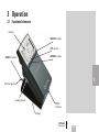
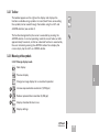
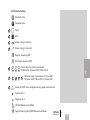
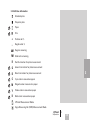
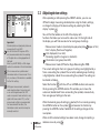
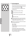
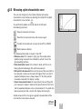
iCPlate2
Plate Measuring Device
User Guide
Edition 2.1
iCPlate2
EN
1
2
Table of Contents
General
3
5
2.1 INTRODUCTION
7
2.2 BRIEF GUIDE TO THE MANUAL
8
2.3 SAFETY
9
2.3.1 Warning
9
2.3.2 General safety tips
9
2.4 PACKAGING AND TRANSPORT10
2.5 BASIC EQUIPMENT AND ACCESSORIES10
2.6 ACCESSORIES11
2.6.1 PlateQuality Software11
2.6.2 Capture Tool software 11
2.6.3 iCPlate2 Target 11
Table of
Contents
1
General
2
Operation
3
Appendix
4
3 OPERATION
13
3.1 FUNCTIONAL ELEMENTS15
3.2 FIRST STEPS FOR USE16
3.2.1 Power-saving mode16
3.2.2 Toolbar17
3.2.3 Identifying the symbols17-21
3.3 ADJUSTING DEVICE SETTINGS
22
3.4FOGRA Measuring Bar FMB setting
23
3.5 INPUTTING A REFERENCE CURVE
24-25
3.6 MEASURING
26
3.6.1 General
26
3.6.2 Calibration
28
3.6.3 Measuring standard plates
28
3.6.4 Measuring polyester plates
29
3.6.5 Measuring film
29
3.6.6 Measuring paper
30
3.6.7 Measurement values
30-31
iCPlate2
1•Table of contents
3
EN
3.7 VISUALLY CHECKING THE DOT
3.8 MEASURING A PLATE CHARACTERISTIC CURVE
3.9 iCPlate2 MAINTENANCE AND CARE
3.9.1 RESET
3.9.2 Replacing the batteries
4 APPENDIX
4.1 TECHNICAL DATA
4.2 SERIAL INTERFACE
4.3 Upgrade to iCPlate2 XT
4.4 DECLARATION OF CONFORMITY
4.5Warranty Information
iCPlate2
1•Table of contents
31
32-33
34
34
35
37
39-40
41
42
43
44
2
General
5
2.1 INTRODUCTION
7
2.2 BRIEF GUIDE TO THE MANUAL
8
2.3 SAFETY
9
2.3.1 Warning
9
2.3.2 General safety tips
9
2.4 PACKAGING AND TRANSPORT10
2.5 BASIC EQUIPMENT AND ACCESSORIES10
2.6 ACCESSORIES11
2.6.1 PlateQuality Software11
2.6.2 Capture Tool software 11
2.6.3 iCPlate2 Target 11
iCPlate2
2•General
Table of
Contents
1
General
2
Operation
3
Appendix
4
EN
2 General
2.1 Introduction
Congratulations! You have just acquired the portable plate measuring device
iCPlate2 made by X-Rite. This device solves one of the most difficult tasks
in the printing industry – quick and accurate quality control of the Computerto-Plate (CtP) process. iCPlate2 meets the needs for the most popular offset
litho and polyester plate types with AM and FM screening. With iCPlate2 XT
where applicable the dot diameter, screen ruling, the screen angle and the
logarithmic visual coverage are calculated and displayed. To avoid having
to check each individual measurement during the linearization of a CtP, the
iCPlate2 XT offers the possibility of measuring an entire curve with up to 100
sample points and then transferring it to a host PC. Beside standard iCPlate2
measurement values, iCPlate2 supports measurement values according to the
Fogra Measuring Bar FMB. Through a purchased password, the iCPlate2 X can
be upgraded to an iCPlate2 XT at any time.
2
The power-saving electronics and LED technology allow up to 30,000
measurements for each set of batteries (2 ordinary commercial AA batteries),
which means that no limits are placed on mobility.
With the icon-based, graphical user interface X-Rite offers the user a simple,
easy to understand operating concept. Included in the complete package are
the iCPlate2 Target and the Capture Tool software. With the Target, you can
check the device at any time and with the Capture Tool software data can be
copied into a word processor, a spreadsheet or another software program.
With the PlateQuality software, X-Rite offers an optional quality control
software to store and trace the measurements.
If you have proposals or ideas for improvements, we will be happy to receive
them. Please contact us via your official specialist dealer or over the Internet
(www.xrite.com).
The X-Rite team
iCPlate2
2•General
EN
2.2 Brief guide to the manual
2
iCPlate2
2•General
Descriptions marked with a
only apply to the iCPlate2 XT and are
not part of the iCPlate2 X specification.
2.3 Safety
2.3.1 Warning
For safety reasons it is absolutely necessary to read through the user’s guide and all of the instructions it contains.
2.3.2 General safety tips
If the safety recommendations and instructions in this User Guide are not complied with, this can lead to measurement errors or data loss or involve physical injury or damage to property.
2
• iCPlate2 is not intrinsically safe. Therefore the device cannot
be used in an environment where there is a risk of explosion.
• iCPlate2 may not be used in an area with strong
electromagnetic fields.
• Use the iCPlate2 in ambient temperatures between 10°C (50°F) and
40°C (104°F), and do not expose the iCPlate2 to direct sun light.
• iCPlate2 should never be opened up. The guarantee expires
immediately upon unauthorized opening of the device. Contact
your official specialist dealer if repairs prove to be necessary.
• To avoid incorrect handling, the iCPlate2 should only be used by
trained personnel.
• iCPlate2 should only be used on dry and stable measuring planes.
• iCPlate2 should be protected against chemicals, corrosive vapors,
strong mechanical vibrations and impacts.
• Use original X-Rite spare parts and accessories only.
• Use the original packaging exclusively when transporting the device.
• The iCPlate2 casing can be cleaned with a slightly damp
cloth (soapy water).
iCPlate2
2•General
EN
2.4 Packaging and transport
Always forward iCPlate2 in the original device case to avoid damage. Safeguard the measuring foot by pushing back the locking device. X-Rite rejects any liability for damage to the iCPlate2 during transport that can be traced back to inadequate packaging or an unsaved measuring foot.
2.5 Basic equipment and accessories
2
The iCPlate2 and the associated standard accessories are supplied in
a device case. Please check the contents of the device case for
completeness on delivery.
The following components must be present:
• iCPlate2 device
• iCPlate2 target
• Quick start guide
• Data cable
• iCPlate2 CD
• Device certificate
• Registration card
10
iCPlate2
2•General
2.6 Accessories
To perform and document quality control, it is often necessary to save the measured data on a PC.
2.6.1 PlateQuality Software
The PlateQuality software stores, visualizes, and documents both
individual measurements and plate characteristic curve measurements.
This gives the operator a saved, visual dot reference to refer back to when needed. Both measurement values and plate images are stored in
a database.
2
2.6.2 Capture Tool software
The Capture Tool software enables you to transfer the measured data
and binary images to your PC and to copy these into a given program
(e.g. word processor, spreadsheet). The screen dot as well as the
associated measurement values will be transferred and can then be used for statistical analysis. This software is an ideal tool for
documenting measuring results.
2.6.3 iCPlate2 Target
The iCPlate2 Target is a long-term stable absolute reference. You can use the iCPlate2 Target to test the device for its exactness, to carry out an upgrade and if necessary to calibrate it.
The reference plate used by X-Rite is an extremely precise cut glass substrate that is metal vaporized and, as is usual in semi-conductor manufacturing, etched out. It is embedded in gray plastic. The reference plate has a lifetime of two years. The expiration date and the serial number are printed on the label.
iCPlate2
2•General
11
EN
3 OPERATION
13
3.1 FUNCTIONAL ELEMENTS15
3.2 FIRST STEPS FOR USE16
3.2.1 Power-saving mode16
3.2.2 Toolbar17
3.2.3 Identifying the symbols17-21
3.3 ADJUSTING DEVICE SETTINGS
22
3.4 FOGRA Measuring Bar FMB setting
23
3.5 INPUTTING A REFERENCE CURVE
24-25
3.6 MEASURING
26-31
3.6.1 General
26-27
3.6.2 Calibration
28
3.6.3 Measuring standard plates
28
3.6.4 Measuring polyester plates
29
3.6.5 Measuring film
29
3.6.6 Measuring paper
30
3.6.7 Measurement values
30-31
3.7 VISUALLY CHECKING THE DOT
32
3.8 MEASURING A PLATE CHARACTERISTIC CURVE
33-34
3.9 iCPlate2 MAINTENANCE AND CARE
35
3.9.1 RESET
35
3.9.2 Replacing the batteries
36
iCPlate2
3•Operation
Table of
Contents
1
General
2
Operation
3
Appendix
4
13
EN
3Operation
3.1 Functional elements
Display
<ENTER> button
<UP> button
<DOWN> button
<RESET> button
3
Positioning Aid
Locking device
RS232
interface
0˚ edge
iCPlate2
3•Operation
15
EN
3.2 First steps for use
Release the measuring head by sliding the locking device on the left side forward. After opening initially or after pressing the <RESET>
button (red button on the bottom side of the measuring head, the start-
up screen appears on the display.
The version number of the firmware and the device serial number are shown on the bottom left of the screen. If you have technical queries, please communicate this information to the manufacturer.
The device’s factory settings have been selected to enable you to begin measuring plates immediately. The iCPlate2 is configured as follows:
• Standard plate
• Lines/cm
• Regular screen (AM)
• Red LED (a standard plate is typically measured with the red LED)
3.2.1
Power-saving
mode
3
16
iCPlate2
3•Operation
The iCPlate2 changes over automatically to power-saving mode after approximately 20 seconds. This is announced by displaying the
‘Sleep’ symbol. The display will then fade out. Tapping any
button on the device will reproduce the last display.
3.2.2
Toolbar
The toolbar appears on the right on the display and displays the
functions available using symbols. A cursor (black frame surrounding the symbol) can be moved through the toolbar using the <UP> and <DOWN> buttons (see section 3).
The function designated by the cursor is executed by pressing the <ENTER> button. In normal operating mode the cursor fades out after approximately 5 seconds, so that no undesired function is executed by the user mistakenly pressing the <ENTER> button. To re-display the cursor simply tap the <UP> or <DOWN> button.
3.2.3
Meaning of the symbols
3.2.3.1 Change display mode
Next display
Previous display
3
Change to image display for a visual dot inspection
Increase representation resolution (1,2700 ppi)
Reduce representation resolution (6,350 ppi)
Display characteristic dot curve
Display settings
iCPlate2
3•Operation
17
EN
3.2.3.2 Move the sub-cursor
Shift the sub-cursor from left to right
Shift the sub-cursor from right to left
Shift the sub-cursor downwards
Shift the sub-cursor upwards
3
18
iCPlate2
3•Operation
3.2.3.3 Device Settings
Standard plate
Polyester plate
Paper
Film
Screen ruling in lines/cm
Screen ruling in lines/inch
Regular screening (AM)
Stochastic screening (FM)
Illumination for plate measurement
R (Red LED), G (Green LED), B (Blue LED)
3
Color for paper measurement C (Cyan LED),
M (Green LED), Y (Blue LED), K (Green LED)
Automatic CMY color recognition during paper measurement
Positive dot %
Negative dot %
iCPlate2 Measurement Mode
Fogra Measuring Bar (FMB) Measurement Mode
iCPlate2
3•Operation
19
EN
3.2.3.4 Other functions
Transfer current record (binary image or characteristic curve) to the
host PC
Device is calculating (during measurement and data transfer)
Device is changing over to power-saving mode
Add reference value
Delete reference value
Restart and delete all previous settings
3.2.3.5 Symbols for measurement results
Screen ruling in lines/cm or lines/inch
Dot diameter in mm (based on a circular dot of the same surface area)
3
Screen angle in °
Visual coverage
20
iCPlate
iCPlate2
3•Operation
3.2.3.6 Status information
Standard plate
Polyester plate
Paper
Film
+
Positive dot %
–
Negative dot %
AM
Regular screening
FM
Stochastic screening
R
Red illumination for plate measurement
G
Green illumination for plate measurement
B
Blue illumination for plate measurement
C
Cyan color measured on paper
M
Magenta color measured on paper
Y
Yellow color measured on paper
K
Black color measured on paper
3
iCPlate2 Measurement Mode
Fogra Measuring Bar (FMB) Measurement Mode
iCPlate2
3•Operation
21
EN
3.3 Adjusting device settings
Important:
Standard plates and polyester plates are
measured with a red LED.
Use of the blue LED or green LED is
only recommended when the coloring
of the plate has a strong proportion of
light pink
hues (e.g. AGFA N90A), as little image
contrast is obtained with red illumination.
3
Film is measured on a professional
illumination table in transmission. This is
why no choice of illumination is available
for the film setting.
With paper measurement, automatic
color selection allows for quicker work,
as no switching between the CMY
colors is required. Color contrast is very
slight with tones under 10%, so that
manual color setting is recommended.
For measurements on black, the
illumination colors needs to always be
manually selected.
22
After unpacking or after pressing the <RESET> button, you can use
iCPlate2 to begin measuring standard plates using the factory settings,
or change the display of the device settings by selecting the ‘Next
display’ symbol
You will find the toolbar on the left of the display with
functions that allow you to move the sub-cursor. On the right side of the display you will find one column for each group of settings.
•Measurement medium (standard plate, polyester plate,
paper or film)
•Dot % display (Positive or Negative)
•Unit displayed (cm or inch)
•Screening algorithm (regular or stochastic)
•Illumination (red, green, blue LED)
•Measurement mode (iCPlate2 or Fogra Measuring Bar FMB)
Select the function
with the <UP> or <DOWN> buttons and execute this by pressing the <ENTER> button. This enables you to move the
subcursor (double black frame surrounding the symbols) consecutively from one group of settings to the next.
When the desired group of settings is selected, fix the cursor by pressing the <DOWN> button on the symbol
and execute the function by
pressing the <ENTER> button. Selection of the settings changes to the next option.
iCPlate2
3•Operation
The current settings for the 6 or 4 groups of settings are highlighted by a frame surrounding the symbols. The currently selected group of settings is highlighted by a black frame surrounding the symbols. The setting can be altered as follows.
When all of the desired settings have been made, change to inputting a reference curve by using 3.4 FOGRA Measuring Bar FMB setting
Select the measurement mode in the device setting
(chapter 3.2.3.3):
iCPlate2 measurement mode
The iCPlate2 measures according to the X-Rite iCPlate2 (or iCPlate II)
standard. The iCPlate2 measures compatible to all other iCPlate2 (or
iCPlate II) devices. In this mode the iCPlate2 uses the specially
developed plate measurement algorithm, where the dots can be
accurately detected.
FOGRA Measuring Bar FMB measurement mode
The iCPlate2 measures according to the FOGRA Measuring Bar
FMB standard. This reference for check-up measurements is the
offset sample plate Fogra Measuring Bar FMB from the German
research institute Forschungsgesellschaft Druck, fogra e.V., München.
Fogra Measuring Bar FMB can be ordered over the internet at
www.fogra.org.
fogra Forschungsgesellschaft Druck e.V.
Streitfeldstr. 19 • D-81673 München/Germany
Phone: +49 (0)89 43182-160 • Telefax: +49 (0)89 43182-100
iCPlate2
3•Operation
3
23
EN
3.5 Inputting a reference curve
24
The user can switch to ‘Input a reference curve’ by selecting the
function in the settings window (see section 3.3).
You will find the toolbar on the left side of the LCD.
An XY diagram of the defined sample points for the current
reference curve is shown on the LCD. The X axis corresponds to the nominal value and the Y axis to the reference value. The currently selected nominal value is indicated on the lower end of the Y axis and the associated reference value on the upper end, provided that a sampling point for the reference curve is planned at this location.
All reference values are reset by selecting the function.
You preset the nominal value using
and
.The position of the
nominal value is marked by a small black arrow on the X axis of the diagram. After initially selecting the nominal value select
to input the value. Thereafter the increment
and
decrement
functions will be highlighted in the toolbar. Per default, the reference value is the same as the nominal value. To enter a 45° reference curve, successively set the nominal value to the value of the patches being measured, select the function
and press <ENTER> button.
To move to the next sampling point, select
.
You delete a value using
and
. The position of the nominal value is marked by a small black arrow on the X axis of the diagram. After initially selecting the nominal value select
to delete the value.
iCPlate2
Example: Inputting a reference curve with the sampling points 5, 10,
30, 60 and 90.
•Select the reference curve window from within the settings window.
•Select the function
with the <UP> or <DOWN> button and
execute this using the <ENTER> button. All reference values are reset.
•Select the function
and execute this function repeatedly until the nominal value is equal to 5% (press <ENTER> button 5 times).
•Select the function
• The default value for this sample point corresponds to the nominal Important:
In normal circumstances the reference
value is set to be equal to the nominal value to obtain a linear plate copy.
However, for certain applications a plate
type dependent process calibration
(pre-compensation) on the plate copy
may be desirable. In this case iCPlate2
offers the possibility of defining the
reference curve in deviation from the
45° straight line.
.
value. Now select the function
to increment or
to decrement and press the <ENTER> button. If the reference curve is altered at least once, the iCPlate2 will create a sample point for the reference curve in this position and save this. The vertical gray line at this
location in the diagram is adjusted simultaneously when the reference value is changed.
• Select the function
and execute this function repeatedly until
the nominal value is equal to 10% (press <ENTER> button 5 times).
• Change the reference value using the steps described for 5%.
• Set further reference values in the same way.
When all of the desired settings have been made, change to the standard
window by using
iCPlate2
25
EN
3.6 Measuring
3.6.1 General
Important:
For repeatable measurements, it is
recommended to hold the measuring head on the right and left side
approximately at the level of the locking element and to lower it. Incomplete
lowering of the measuring head leads
to a blurred image and consequently to
an inexact measurement result.
Position the instrument by means of the positioning target on the patch and lower the measuring head. The
symbol will appear in the LCD. Keep the measuring head lowered until the measurement value is displayed. If the measuring head was released before the completion of the measurement, indicated by the
blinking
symbol, the measurement must be repeated.
Important: For precise measurements, please always make sure the medium
and the device is positioned on a flat and stable surface. Please always position the entire instrument on the medium (the 4 feet and the measuring head).
3
The measuring device shows the measurement result after a
successful measurement.
You will find the toolbar on the left side of the LCD with the following functions:
Change to image display for a visual dot inspection
Change to characteristic curve display
Device settings
26
iCPlate2
3•Operation
For regular screening in the display you will find:
DOT xx.x % Measured dot area
Identified screen ruling in lines/cm or lines/inch
Dot diameter in µm (based on a circular dot of the same
surface area), provided that a closed dot was present
Screen angle in °
Visual coverage
All or only some of the measurement results are shown depending on the patch measured and the algorithm (regular or stochastic screening).
You will find the status of the device settings on the lower right
section of the display (see section 3.2.3.6 for the explanation of
the symbols).
Important:
In a regular screen, the screen ruling,
dot size and screen angle will always
be shown if the dot area has closed
dots (highlights and shadows). These
parameters are not shown for middle
tones, especially for chain dots.
The visual coverage is a ‘density’
measurement, which is not compatible with any current standard and can
only be used for comparative analysis.
For density measurement, we recommend using a X-Rite Densitometer
conforming to standards.
Only the dot area is usually
determined in stochastic screens.
However, use of image analysis
algorithms makes it possible to
measure individual dot sizes in
stochastic screens as well. The
dot size will be displayed if the
stochastic screen is set and screen
tones < 10% are measured. This
means the laser image quality can
be verified easily.
iCPlate2
3•Operation
27
EN
3
3.6.2 Calibration
As the iCPlate2 calibration is done automatically, no calibration or “zeroing” on the plate is needed. After inputting into the device the appropriate settings, measurements can be executed without any further calibration.
A zeroing on the plate is however required for the “Visual Coverage” value. This zeroing is done by a measurement on the medium (e.g. plate ground).
To check the absolute accuracy of the iCPlate2, X-Rite offers the iCPlate2 Target. With the help of this tool, the device can be checked and calibrated (see section 2.6.2).
3.6.3 Measuring standard plates
3
28
iCPlate2
3•Operation
Standard plates and polyester plates are measured with a red LED. Use of the blue LED or green LED is only recommended when the coloring of the plate has a strong proportion of light pink hues (e.g. AGFA N90A), as little image contrast is obtained with red illumination.
Important:
As the measurement algorithm is designed and optimized for finding dots in a picture, measuring a 0% patch or a 100% patch can be difficult since the
software is designed for having the best possible performance for dot measure-
ments. For this reason, and in certain cases only, the displayed measurement value for the 0% or the 100% may not be correct. The measuring range for full precise readings is limited to 1% to 99%.
Therefore, incorrect 0% or 100% patch measurement result that may occur in certain cases do not indicate that the instrument is functioning poorly. Please use the iCPlate2 Target to check the accuracy of the device (see chapter 2.6.2).
3.6.4 Measuring polyester plates
Standard plates and polyester plates are measured with a red LED. Use of the blue LED or green LED is only recommended when the
coloring of the plate has a strong proportion of light pink hues, as
little image contrast is obtained with red illumination.
Important: Due to the grainy background of polyester plates the repeatability may
be up to +/- 0.8 %. For the same reason and because of the algorithms used for
measuring dots, measurements below 5% or on a 100% patch can sometimes be incorrect. Therefore, the measuring range for exact readings is limited to 5%
to 99%. Please note that incorrect measurements for 0% or 100% patches do
not indicate that the instrument is functioning poorly. If you were to get incorrect
measurements for 0% or 100% patches, please use the iCPlate2 Target to check
the accuracy of the device (see chapter 2.6.2).
3.6.5 Measuring film
Film should be measured on a professional illumination table in
transmission mode. This is why no choice of illumination is available for the film setting.
Important: Please make sure that the light table is equipped with a flat and
stable glass.
iCPlate2
3•Operation
3
29
EN
3.6.6 Measuring paper
For paper measurements, automatic color selection allows for quicker work, as no switching between the CMY colors is required. Color contrast is very slight with tones under 10%, so that manual color setting is recommended. For measurements on black, the color (K) must always be selected manually.
The iCPlate2 is equipped with a video camera, which measures the geometrical dot size, relevant for plate readings. For prints, the densitometric dot size needs to be measured, as this measurement corresponds to the visual impression. Therefore, the iCPlate2 is not the ideal device for measurements of the dot area on paper. Nevertheless, it can be used for visual dot analysis of prints.
3.6.7 Measurement Values
3
30
3.6.7.1 Dot area
This value represents the area coverage of the measured patch. With the image analysis algorithm, dust and image errors are
eliminated.
3.6.7.2 Screen ruling
Depending on the settings, the screen ruling is displayed either in Lines/inch or Lines/cm.
Important: The screen ruling is not shown for FM screening and for middle tones, especially for chain dots in AM screening. In a regular screen, the screen ruling will always be shown if the dot area has closed dots
(highlights and shadows).
iCPlate2
3•Operation
3.6.7.3 Dot diameter
The diameter of the dots is displayed in µm. The calculation is based on a circular dot of the same surface area.
Important: The dot diameter is not shown for middle tones, especially for chain dots in AM screening. In a regular screen, the dot diameter will always be shown if the dot area has closed dots (highlights and shadows).
The image analysis algorithms make it possible to display the dot diameter for
stochastic screen when the dot area is smaller than 10%.
3.6.7.4 Screen angle
Hold the iCPlate2 parallel to the edge of the plate to get a correct value of the screen angle in degrees.
Important: The screen angle is not shown for FM screening and for middle tones, especially for chain dots in AM screening. In a regular screen, the screen angle will always be shown if the dot area has closed dots (highlights and shadows).
3.6.7.5 Visual Coverage
The visual coverage is a ‘density’ measurement, which is not
compatible with any current density standard and can only be used
for comparative analysis. For proper density measurements, we
recommend using a X-Rite Densitometer conforming to
standards.
For the “Visual Coverage” value, a zeroing on the medium is
needed. The zeroing is done by a measurement on the medium
(e.g. plate ground).
iCPlate2
3•Operation
3
31
EN
3.7 Visually checking the dot
After a measurement the picture will be held in the device’s memory until the next measurement and can be displayed or transferred to a host PC at any time by selecting the function.
As usual you will find the toolbar on the left side of the LCD with the following functions.
Increase representation resolution to 12,700 ppi
Reduce representation resolution to 6,350 ppi
Transfer the current binary image to the host PC via RS232
Back to previous display
3
32
Depending on the setting the binary image will be displayed with a resolution of 6,350ppi (a pixel corresponds to 4 micron x 4 micron) or 12,700ppi (a pixel corresponds to 2 micron x 2 micron).
A light gray ruler in the top left corner shows the current resolution and the associated length of the line:
• 200µm at 6,350 ppi
• 100µm at 12,700 ppi
This means that an absolute size comparison of the represented dots
is possible immediately.
Transferring the binary image to a host makes it possible to
document the dot quality. X-Rite offers the Capture Tool software,
which can accept the binary image and copy it into any application
that supports the Windows clipboard.
iCPlate2
3•Operation
3.8 Measuring a plate characteristic curve
The user can change from the standard display to the plate
characteristic curve function by selecting the symbol for the plate characteristic curve function
You will find the toolbar on the left side of the LCD with the following functions:
Reset all measurement values
Reset the last measured value and measure again
Transfer the characteristic curve to the host PC via RS232
Back to previous display
The following information is shown in the LCD:
• Reference curve: this is drawn in light gray. The sample points (patches being measured) are indicated by vertical lines at the
corresponding locations.
• Plate characteristic curve: this is drawn in black, with the curve being adjusted accordingly after each measurement.
• Next patch to be measured: the nominal value of the next patch to be measured is shown on the lower left edge of the Y axis and its expected reference value is shown above it. If all of the patches have been measured this display is empty.
• Current measurement value: the measurement value of the patch just measured is shown in black on the top left corner of the Y axis and the expected reference value is shown below it. If no patch has been measured yet after a restart, this display will be empty.
A black arrow on the X axis gives a graphic representation of the next nominal value to be measured.
iCPlate2
3•Operation
3
33
EN
Example: Measuring a plate characteristic curve with the sample
points 5, 10, 30, 60 and 90 (45° reference curve):
3
34
iCPlate2
3•Operation
• Select the function
with the <UP> or <DOWN> button and
execute this using the <ENTER> button. All reference values are reset. The nominal value 5% and the reference value 5% are shown.
• Measure the 5% patch. The measured value is shown at the top edge of the Y axis and the 5% reference value is shown below it. The nominal value of 10% and the reference value of 10% are shown for the next patch.
• Measure the 10% patch. The measured value is shown at the top edge of the Y axis and the 10% reference value is shown below it. The nominal value of 30% and the reference value of 30% are shown for the next patch.
• Should you have measured the 20% patch instead of the 10% patch, put the measurement cursor back by one patch by selecting the
function with the <UP> or <DOWN> button and then
pressing the <ENTER> button. The nominal value, reference value and current measurement value will be put back accordingly.
• Measure the 30%, 60% and 90% patch in the same way. No
new nominal value will be shown now. The curve can then be transferred to the host PC by selecting the icon
and pressing the <ENTER> button.
3.9 iCPlate2 maintenance and care
3.9.1
Reset
If the microprocessor becomes blocked (e.g. after changing
batteries or another disruption), then press the <RESET> button (red button on the bottom side of the measuring head). The device will respond with the start-up display.
If you have technical questions for the manufacturer, you will find the firmware version and serial number in this display. Please state these when requesting verifications.
3
iCPlate2
3•Operation
35
EN
3.9.2
Replacing the batteries
The batteries must typically be replaced after 30,000 measurements. The iCPlate2 monitors the battery voltage and shows an ‘empty
batteries’ symbol
when the batteries need to be replaced soon. Replace the batteries as quickly as possible in this instance.
Take the following steps when replacing the batteries:
• Loosen the battery cover screw with a commercially available
flat-tip screwdriver.
• Remove the cover from the battery compartment.
• Remove the two old batteries.
• Insert the new batteries while taking the polarity into account. The polarity and the mounting position are illustrated in the battery compartment.
• Put the battery cover back on again.
• Tighten the battery cover screw.
• Dispose of the old batteries in accordance with regulations.
• Push the <RESET> button.
Important:
Always replace both batteries at the
same time.
If you are not using the device for a
long time, please take the batteries
out of the battery compartment.
3
36
iCPlate2
3•Operation
4 APPENDIX
4.1 TECHNICAL DATA
4.2 SERIAL INTERFACE
4.3 Upgrade to iCPlate2 XT
4.4 DECLARATION OF CONFORMITY
4.5Warranty Information
37
39-40
41
42
43
44
iCPlate2
3•Operation
Table of
Contents
1
General
2
Operation
3
Appendix
4
37
EN
38
iCPlate2
4 Appendix
4.1 Technical data
iCPlate2 X
X
6,350 ppi
iCPlate2 XT
Functions
Dot area %
Screen ruling in lines/cm or lines/inch
Dot diameter
Screen angle
Visual coverage
Binary image display
Plate characteristic curve
References
X
X
X
X
X
6,350 ppi and 12,700 ppi
100 measurements
100 references
Test measurements
Standard plates
Polyester plates
Film
Paper
Positive and negative samples
Regular screen (AM)
Stochastic screen (FM) 1st and 2nd order X
X
X
X
X
Measurement technique
Sensor
Sensor resolution
Viewing area per pixel
Viewing area
Analysis
Illumination
Repeatability
Measurement time
Screen ruling range (AM)
CMOS 648 x 488
12,700 ppi
2 µm x 2µm
ca. 1.3mm x 1mm
Image analysis algorithms
RGB LED ring optics
± 0.5%
3.4 sec (typ.)
26 l/cm – 147 l/cm
X
X
X
X
X
X
X
4
iCPlate2
4•Appendix
39
EN
iCPlate2 X
iCPlate2 XT
Dot size range (FM)
Dot diameter resolution
Screen angle resolution
Visual coverage
10 µm – 50 µm
1 µm
3°
0 - 2.2
User Interface
Graphical display
User interface
160 x 80 pixels LCD grayscale
Symbol oriented
Power supply
Power supply
Measurements per set of batteries
2 AA batteries
30,000 (typ.)
Data interface
Interface
Baud rate
Serial (RS232)
115,200
Mechanical data
Dimensions 4.8 x 7.3 x 14.5cm (1.7 x 2.9 x 5.7 in)
Weight
Approx. 400 g
Operating conditions
Temperature
Relative humidity
10°C to 40°C
10% to 80% non-condensing
Storage conditions
Temperature
Relative humidity
-20°C to 70°C
10% to 90% non-condensing
(Right reserved to make technical alterations)
4
40
iCPlate2
4•Appendix
4.2 Serial interface
The iCPlate2 is equipped with a RS232 interface. To obtain access to the serial interface socket, remove the black cover on the rear of the measuring head.
The serial interface is configured as follows in the factory:
• Standard RS232 with TxD cable
• 115,200 baud
• 8 bit, 1 stop bit, no parity
4
iCPlate2
4•Appendix
41
EN
4.3 Upgrade to iCPlate2 XT
The iCPlate2 X may be upgraded to an iCPlate2 XT. The functions which you did not purchase initially may be added by inputting a special code. When you request the upgrade from your dealer, you will receive a code allowing you to access the additional functions. To activate the upgrade, proceed as followed:
1. Press the <RESET> button and keep it pressed
2. Press the <DOWN> button and keep it pressed
3. Release the <RESET> button
4. Release the <DOWN> button. Thereafter, the iCPlate2 is in the programming mode. A four4 digit code is displayed.
5. Use the <UP and <DOWN> button to set the code for this digit
6. Press the <ENTER> button (the cursor moves the next digit)
7. Repeat step 5 and 6 until all digits are entered
8. After the last digit, the additional functions are available. On the startup screen, the version “XT” is displayed.
4
42
iCPlate2
4•Appendix
4.4 Declaration of conformity
CE-DECLARATION OF CONFORMITY
The undersigned, representing the following manufacturer:
X-Rite Europe AG
Althardstrasse 70
CH-8105 Regensdorf
Switzerland
herewith declares that the product:
X-Rite iCPlate2
Plate Measuring Device
is in conformity with the provisions of the following CE
directive(s) (including all applicable amendments):
73/23/EEC
89/336/EEC
Electrical equipment for use within specified voltage limits
Electromagnetic compatibility
and the standards and/or technical specifications referenced overleaf have been applied.
The last two digits of the year in which the CE marking was affixed: 03
CH-8105 Regensdorf, 1 August 2003
Th. Senn
Vice President
C. Benz
Product Manager
4
iCPlate2
4•Appendix
43
EN
4.5 Warranty Information
4
44
X-Rite, Incorporated (“X-Rite”) warrants each instrument
manufactured to be free of defects in material and workmanship
(excluding battery pack) for a period of 12 months, unless
different local regulations apply. This warranty shall be fulfilled by
the repair or replacement, at the option of X-Rite, of any part or
parts, free of charge including labor, F.O.B. its factory or authorized
service center.
This warranty shall be voided by any repair, alteration, or
modification, by persons other than employees of X-Rite, or those
expressly authorized by X-Rite to perform repairs, and by any abuse,
misuse, or neglect of the product, or by use not in accordance with
X-Rite’s published instructions.
X-Rite reserves the right to make changes in design and /or
improvements to its products without any obligation to include these
changes in any products previously manufactured. Correction of
defects by repair or replacement shall constitute fulfillment of all
warranty obligations on the part of X-Rite.
THIS WARRANTY IS EXPLICITLY IN LIEU OF ANY OTHER
EXPRESSED OR IMPLIED WARRANTIES, INCLUDING ANY IMPLIED
WARRANTY OF MERCHANTABILITY OR FITNESS FOR ANY
PARTICULAR PURPOSE. THIS WARRANTY OBLIGATION IS LIMITED
TO REPAIR OR REPLACEMENT OF THE UNIT RETURNED TO X-RITE
OR AN AUTHORIZED SERVICE CENTER FOR THAT PURPOSE.
This agreement shall be interpreted in accordance with the laws of
the State of Michigan and jurisdiction and venue shall lie with the
courts of Michigan as selected by X-Rite, Incorporated.
iCPlate2
4•Appendix