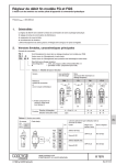
1
Dear Customer,
Thank you for using information provided on our website. You can check the latest
prices and place orders for products contained in this document by visiting our
website at:
http://www.partxpres.com
Information contained in this document was provided by the product manufacturer
or service provider. Although great care has been taken to ensure correctness and
relevance of the information, PARTXPRES does not assume any responsibility or
liability for the information contained herein.
Customer Service
PARTXPRES
TECHKON
Manual
Digital MicroScope
SpectroPlate
Software
SpectroConnect
TECHKON manuals, technical documentation and programs are copyrighted. Reproduction,
translation or transfer to an electronic medium – in whole or in parts – is prohibited.
TECHKON software is the intellectual property of TECHKON GmbH. Purchase of the
software grants the user a license for the use on one computer only. Programs may only be
copied for back-up purposes.
TECHKON can not be held liable for any damages that may occur by the use of TECHKON
products.
The TECHKON team takes great care in producing this manual. Nevertheless, we can not
fully guarantee the complete absence of errors. TECHKON GmbH and the authors can not
be held liable neither for any possibly incorrect statements nor their consequences.
Product that are not made by TECHKON GmbH are mentioned for information purposes
only and such statements do not represent trademark infringement. All registered trademarks are recognized.
TECHKON products and product names are registered internationally under several intellectual patents and trademarks.
Specifications can be subject to change without notice.
Version 1.5, May 2011
You can reach us at the following address:
TECHKON GmbH
Wiesbadener Str. 27 • D-61462 Königstein/Germany
Telephone: +49 (0)6174 92 44 50 • Telefax: +49 (0)6174 92 44 99
E-mail: [email protected] • http://www.techkon.com
Welcome
We welcome you among the worldwide community of users of TECHKON
products. We are happy that you have selected this high-quality measurement
instrument. It will be a valuable tool for your day-to-day quality control tasks.
With this manual we invite you to learn how to use SpectroPlate.
The manual is divided into three chapters:
Chapter 1: How to use TECHKON SpectroPlate
Chapter 2: Description of measurement functions
Chapter 3: How to use the Windows software SpectroConnect
For the first steps we recommend to read chapter I; in particular paragraph 1.4.
You will be fascinated that after only ten minutes you will know how to work with
SpectroPlate. The second chapter will show you detailed insight into the measurement functions and chapter 3 is about the Windows software SpectroConnect,
which is part of the package.
Please get the device registered by using the detachable registration card, which
is the last page of this manual. That way we can keep you updated about product
news.
Please visit us as well on the internet at http://www.techkon.com.
You will find useful information about the complete product range and new software versions.
Do you have any suggestions for improvements or do you require information that
goes beyond the contents of this manual? We will be glad to hear from you. Your
suggestions or questions make an important contribution to the continuous optimization of our documentation and products.
Your TECHKON Team
Content
Chapter 1: How to use TECHKON SpectroPlate
1.1
1.2
1.3
1.4
1.5
Product description........................................................................ 5
Performance packages and packing list...................................... 8
Design of SpectroPlate................................................................... 9
Working with SpectroPlate.......................................................... 10
Care and maintenance.................................................................... 18
Chapter 2: Description of measurement functions
2.1 Measurement functions of SpectroPlate Start......................... 21
2.2 Additional functions of SpectroPlate Expert............................ 22
2.3 Additional functions of SpectroPlate All-Vision...................... 29
Chapter 3: How to use the Windows software SpectroConnect
3.1
3.2
3.3
3.4
3.5
3.6
3.7
Software description...................................................................... 31
Installation......................................................................................... 31
Overview........................................................................................... 32
Software module “SpectroPlate settings”................................ 33
Software module “Transfer curve”............................................. 35
Software module “Export”........................................................... 36
Software module “Digital Microscope”..................................... 37
Appendix:
Technical specifications
Manufacturer certificate
EC-Declaration of Conformity
Registration card
Chapter 1
How to use TECHKON SpectroPlate
1.1 Product description
TECHKON SpectroPlate – printing plate measurement right on the spot !
Today in the age of Computer-to-Plate it is obvious: Without quality control in prepress, there is no guarantee for quality in print. Thus the measurement of the right
dot transfer on offset printing plates is a key segment of comprehensive process
control in the printing industry.
However, measurement is only useful if the appropriate measurement technology
is applied. Some years ago using densitometers on printing plates was common
practice. But densitometers are designed for measuring on printed papers leading
to limits when reading on plates. At present, plate measurement devices based on
microscopic image capture and processing are the established standard.
SpectroPlate unifies all advantages of this modern measurement technology in
a compact, hand-held instrument. This product series and all other TECHKON
products are the result of many years of expertise in designing and manufacturing
high-quality measurement devices for the printing industry. Our four TECHKON
guidelines for perfect measurement technology are consequently applied:
1. Easy and quick operation
2.High measurement accuracy
3. Robust engineering and reliability
4. Ergonomic and functional design
The measurement accuracy of a plate measuring device is determined by the quality
of the optical system and the performance of the image processing algorithms.
SpectroPlate meets the highest standards in this respect. The sample is illuminated
uniformly with spectral broadband light. The microscopic image is captured by a
precision optical lens system and a high resolution CMOS color matrix sensor with
high dynamic range. The processing of the detailed color image is performed by a
powerful graphic signal processor and sophisticated imaging algorithms. All relevant
quality parameters for correctly manufactured printing plates are shown on the
LCD display.
Manual TECHKON SpectroPlate Chapter 1 – How to use SpectroPlate
Page 5
Thanks to the excellent image capture quality and the ingenious graphic calculations,
SpectroPlate can read precisely any screen size and screen technology: FM, AM
or Hybrid screen. The spectrally white illumination and dynamic color evaluation
permits reading all kinds of plate types and coated surfaces.
SpectroPlate lets you see things normally hidden to the human eye. It shows the
raster dots on a film or a printing plate in large magnification on the device display
or optionally on a computer screen. It lets you visually judge printing plates and
discover any soiling or exposure errors now that the structure of the raster dots is
visible.
A specific strength is the image transfer of uncompressed high-resolution files to
the PC where they can be stored, edited or sent over the internet. Geometric sizes
of dots or lines can be retrieved in micrometer- or mils dimensions.
The supplied Windows software connects the device to a PC. Measured values and
transfer curves are displayed and stored. The display of comparisons to target values, the data export to Microsoft Excel™ and the compatibility to RIP applications
are additionally useful functions of SpectroConnect. An exceptional feature is the
enlarged view of the microscopic images.
All devices are factory-made calibrated to the official reference Fogra Measuring Bar
FMB resulting in high long-term absolute accuracy and an excellent inter-instrument
agreement. Additionally, time-consuming calibration procedures prior to measurements are obsolete.
The technical specifications are listed on the last pages of this manual.
Page 6
Manual TECHKON SpectroPlate Chapter 1 – How to use SpectroPlate
All advantages at a glance
• Accurate measurements on all popular offset plate types
• For AM, FM, Hybrid, from low- to high-res screening
• Measures film in reflection and transmission
• Can be used as „Digital Microscope“
• Measurement on CMYK-print
• Operation self explanatory
• With digital ruler
• Several menu languages selectable
• Aesthetically appealing and ergonomic,
functional design
• Lightweight and compact; fits like a glove
• Direct, secure positioning on the sample
• Solid, rugged design; works well in
harsh industrial environments
• No mechanically moving parts;
therefore no wear and tear,
i. e. maintenance free
• Measurement time
approximately 1 second !
• Immediately ready to
use after switching on
• Highest absolute accuracy thanks
to direct reference to absolute
standard Fogra Measuring Bar FMB
• Devices are factory-made calibrated
permanently to accredited reference FMB
• No time-consuming calibration necessary
• High-resolution CMOS color matrix sensor
• High-precision optical system “Made in Germany”
• Homogeneous, spectral-broadband LED illumination
• Sophisticated image calculation and powerful signal
processing
• Mobile, portable unit, also for remote use without PC
• Quickly rechargeable high-capacity batteries, with charging console
• Upgrade from Start- to Expert-version via firmware upload from the PC
• USB port for the speedy transfer of measurement data to the PC
• Comprehensive software SpectroConnect included
Manual TECHKON SpectroPlate Chapter 1 – How to use SpectroPlate
Page 7
1.2 Performance packages and packing list
Three different performance packages
SpectroPlate is available in three different types of performance packages:
The entry-level model Start is for dot percentage measurements on all popular
types of printing plates, film and CMYK-print.
The Expert-version additionally features the recording of complete transfer curves
and the possibility to analyze geometric objects within the device.
The Start-version can easily be upgraded to the Expert-model by a post-purchase
upload from the PC. The All-Vision version measures precisely on low-visible, processless offset printing plates.
SpectroPlate Start
•% dot measurement
•Screen angle in °
•Screen frequency in l/cm and lpi
SpectroPlate All-Vision
same as Expert and additionally:
•Measurement of chemistry-free,
processless plates with very low visible
contrast
SpectroPlate Expert
same as Start and additionally:
•Dot transfer curve
•Dot gain curve
•Geometrical analysis: diameter,
distance in micrometer and mils
•Memory for 100 data sets
•Average measurement
Contents of delivery:
•Measurement device SpectroPlate
•Carrying case
•Charging console with white standard
•AC adapter with universal plugs for
Europe, UK and USA
•This manual with ISO 9000 compliant
certificate
•USB cable for PC connection
•CD with software SpectroConnect
The carrying case protects SpectroPlate and
parts
Accessories:
• Software upgrade from SpectroPlate Start to Expert; Hardware upgrade to All-Vision
• Replacement parts: charging console with white standard, rechargeable battery
• Offset printing plate reference Fogra Measuring Bar FMB; (can be purchased at
Fogra Forschungsgesellschaft, www.fogra.org)
Page 8
Manual TECHKON SpectroPlate Chapter 1 – How to use SpectroPlate
1.3 Design of SpectroPlate
SpectroPlate is a solidly designed measurement device which is very functional and
easy to use. It is compact in size; the buttons can be reached with the right index
finger when the device is held with the right hand. The LCD display is inclined
towards the user, so the display information can be read clearly. SpectroPlate can be
easily positioned on the measurement sample.
The measurement sample is illuminated uniformly by spectrally white LEDs.
The viewfinder helps selecting the right positioning of the measurement aperture.
Additionally, the magnified live-image in the LCD display verifies the validity of the
right spot to measure.
Charging contacts
Device label
with serial number
Device base
Visible
measurement
aperture
Battery case
USB-connector
for PC connection
Green
measurement
button (also for
switching on)
Navigation buttons
Right hand grip
zone
Backlit device
display
UK
2.
USA
Europe
1.
Ceramic
white standard
Connect the plug of the AC adapter (1.)
with the charging console (2.). The AC
adapter can be used universally for 100 –
240 V and 47 – 63 Hz. Use only the original
TECHKON SpectroPlate AC adapter. The
use of other power sources is hazardous !
There are three adapter plugs for different
countries. To change an adapter plug, just
pull it off the AC adapter and push in the
new one. Make sure it is connected firmly !
Manual TECHKON SpectroPlate Chapter 1 – How to use SpectroPlate
Page 9
1.4 Working with SpectroPlate
Switching on and off
SpectroPlate is switched on by pressing the green measurement button. It is immediately ready to measure.
If no button is pressed within two minutes, the device will switch off automatically.
Switching it on again with the green measurement button will show on the display
the last measurement done. There is no button to turn SpectroPlate off.
Charging
The battery status is displayed as a battery symbol in the lower left corner of the
LCD screen, when the unit is turned on.
When the battery turns empty, the battery symbol starts to flash. In this state
several measurements still can be obtained; but it is time to put it on the charging
console. Charging starts automatically by placing the device on the charging console.
Please keep the charging contacts at the bottom of the device and on the charging
console clean. To avoid scratches, always use a soft cloth or a similar soft material. If
oxidized, we recommend to use a cotton bud soaked with metal contact spray.
Five seconds after placing the device on the console the display will show a clock
and an animated battery symbol. When the symbol displays a full battery, the charging is completed and the battery is fully charged. Completely charging an empty
battery will take approximately four hours.
SpectroPlate has a regulated charging management. This means it will power-charge
an empty battery, so the device can be used again after a few minutes. On the
other hand, there is no overcharging of full batteries. You can park the device on
the charging console when not in use. This way it is guaranteed to have always an
operational measurement instrument at hand.
Up to 10.000 measurements can be carried out with one battery charge.
Page 10
Manual TECHKON SpectroPlate Chapter 1 – How to use SpectroPlate
How to measure
After switching on SpectroPlate, it is
instantly ready to measure. No calibration is to be carried out. Just position
the measurement aperture above the
area to be measured and press the
green button shortly with your right
index finger. Within one second the
resulting measurement value will appear
on the display of the device.
Please make sure to perform measurements on flat surfaces only. The measurement
aperture has to be directly on the sample without any distance in order to ensure
the correct field of depth of the optical system. On the bottom of the device there
are anti-slip rubbers which prevent the device from being moved during a measurement.
Device settings with the display menu
The SpectroPlate display is divided logically into a section where the measurement
results are displayed and a frame of “soft keys”.
Notice: In the Start-version of SpectroPlate certain “soft keys” will be not selectable and are shaded in gray. These are the functions which are only available for the
Expert- and All-Vision-model.
Pressing shortly on one of the Arrow buttons (1.) will move an active cursor from
“soft key” to “soft key” around the frame. An active “soft key” is indicated by
inverse appearance. By pressing the Enter button (2.) a function behind a “soft key”
is selected and a selectable menu appears. Within such a menu again the navigation
is done via the Arrow buttons and the selections are made with the Enter button. The red Escape button (3.) is for canceling any procedure and for closing open
menu windows in order to return to the measurement mode.
3.
1.
2.
1. Arrow buttons
2. Enter button
3. Escape button
Manual TECHKON SpectroPlate Chapter 1 – How to use SpectroPlate
Page 11
Notice: The following instruction describes the use of the Start-version of SpectroPlate. It applies to the Expert- and All-Vision-model as well. Supplementary functions of Expert and All-Vision will be explained in the following chapter in detail.
Thanks to the interactive device menu, settings are very easy to adjust. The display
is divided logically into the following segments:
5.
1.
6.
2.
3.
7.
4.
8.
9.
10.
The left side shows the measurement results:
1. Dot percentage
2. Screen ruling (= screen frequency)
3. Screen angle
4. Battery status, zoom factor, image mode
The center displays the captured
microscopic image (5.).
The right and lower corner contains the
interactive “soft keys”:
6. Zoom function
7. Device settings
8. Setting of the screen type
9. Measurement function
10.Plate type / measurement conditions
Menu: Device settings
The “soft key” with the tool symbol (see picture above, 7.) opens the window for
the device settings. Within this window you can navigate with the Arrow buttons
and select with the Enter button. The red Escape button brings you back to the
measurement mode.
1.
*
2.
3.
4.
5.
6.
*
7.
8.
* only SpectroPlate Expert and All-Vision
Page 12
Manual TECHKON SpectroPlate Chapter 1 – How to use SpectroPlate
Description of the device settings:
1.
1. The SpectroPlate INFO screen shows
the type of device (Start, Expert, All-Vision),
the software- and hardware version as well
as the serial number.
2. Performing a calibration is described on
the next page.
3. Displays a grid array.
4. Sound will activate an acoustic signal
after each measurement.
5. The LCD display contrast can be turned
darker or brighter.
6. Sets the menu language of the device.
8.
7. All measurement values get a time- and
date stamp. This information will be visible
when the data is transmitted to the PC
software SpectroConnect.
8. A reset puts the device to factory settings. Attention ! All stored measurement
values and recently made calibrations will
be deleted. Only the factory-set calibration
values are still valid.
Menu: Measurement functions
When the “soft key” in the left section of the lower bar of the display is activated,
a windows opens where you can select the measurement functions. The measurement functions listed below are describe in chapter 2.
Index of the measurement functions:
1.
2.
3.
4.
1.% dot measurement
2.Dot transfer curve
3.Dot gain curve
4.Geometrical analysis
Manual TECHKON SpectroPlate Chapter 1 – How to use SpectroPlate
p. 21
p. 23
p. 26
p. 27
Page 13
Calibration
SpectroPlate is factory-side calibrated. A white calibration adjusts the digital camera
module. The screen calibration is for exact adjustment of dot percentage measurements towards the reference plate Fogra Measuring Bar FMB. The calibration
remains permanently and the devices are long-term stable. This means that there
are no time intervals for re-calibration necessary.
To ensure the correct operation of the device, we recommend to perform check-up
measurements once a month. Before measuring make sure that the measurement
aperture is free of dust. In case it has to be cleaned use oil-free, clean compressed
air or an optics brush.
The suitable reference for check-up measurements is the offset sample plate Fogra
Measuring Bar FMB from the research institute Forschungsgesellschaft Druck, Fogra
e.V., München.
It includes two percentage wedges, one periodic AM screen, one non periodic FM
screen and a documentation with a protocol listing reference values taken with a
laboratory instrument by the institute.
Fogra Measuring Bar can be ordered
over the internet at:
www.fogra.org.
Fogra Forschungsgesellschaft Druck e.V.
Streitfeldstr. 19
D-81673 München / Germany
Phone: +49 (0)89 43182-160
Fax: +49 (0)89 43182-100
www.fogra.org
We recommend to make five measurements per measurement patch and take the
average value in order to level out measurement deviations caused by inhomogeneous percentage patches due to the production process of the FMB. The averaged
measurement results of SpectroPlate have to be within the following tolerances:
AM screen (periodic):
± 0,5 %
FM screen (non periodic): ± 1,0 %
If the measurement results are out of tolerance, make a white calibration and try
again. If the values are still out of range, it is necessary to perform a screen calibration on a Fogra Measuring Bar FMB.
Page 14
Manual TECHKON SpectroPlate Chapter 1 – How to use SpectroPlate
Sample offset plate Fogra FMB
1.
2.
1.
2.
The 0 % (1.) and 100 % (2.) patches are not
measured.
Protocol with list of measurement values
White calibration:
To carry out a white calibration, place the
measurement device on the clean white
standard, which is part of the charging console (see picture on page 9).
Select “Calibration” and then “White Calibration” from the menu “device settings”
and follow the instructions on the device
display.
The calibration is confirmed by an acoustic
signal.
Manual TECHKON SpectroPlate Chapter 1 – How to use SpectroPlate
Page 15
Calibration procedures for AM screen and
FM screen are carried out separately.
By selecting “Calibration” and then “Target
Values FMB AM 60/cm” or “Target values
FMB FM 22/µm” from the menu “device settings” you get a window where you can edit
the reference values
Edit the reference values from the list of the
FMB protocol into the table in SpectroPlate.
Now perform the AM or FM measurements
on the FMB plate.
Select “Calibration” and then “Screen Calibration AM or FM” from the menu “device
settings”.
Place the measurement device on the clean
white standard, which is part of the charging
console (see picture on page 9) to carry out
a white calibration.
Edit the reference values from the list of the
FMB protocol into the table in SpectroPlate.
Now perform the AM or FM measurements
on the FMB plate.
Page 16
Manual TECHKON SpectroPlate Chapter 1 – How to use SpectroPlate
Setting the plate type
SpectroPlate will carry out optimized image calculations depending on the type of
offset printing plate used. Therefore the type of printing plate has to be selected.
Also for measurements on film or printed paper the right setting has to be made
first.
1. Select wether the plate has positive or
negative processing properties. The dot percentage value will be shown as dot increase
or decrease accordingly.
1.
Select the type of printing plate you use.
2.
3.
4.
5.
6.
Your plate is not in the list ?
Please contact us ! This list is permanently
updated when new plates appear on the
market.
Plate type is shaded ?
Upgrade to the All-Vision model !
See chapter 2.3 for details.
2. Fogra Measuring Bar:
This setting is to be used for the check-up
measurements on the Fogra Measuring Bar
FMB only.
3. Aluminium plates:
Should the exact type of printing plate not
be listed, then select here the type which
describes best.
4. Measurements on paper:
Geometric dot percentage measurements
on paper are only useful for a few specific
applications. The geometric dot percentage
measured precisely by SpectroPlate is not
comparable to the dot percentage value
based on the Murray-Davies formula measured with a densitometer.
Please note that the standards for measurements on printed paper describe the use of
densitometers and spectrophotometers.
5. Film measurement reflection:
Simply place the film on a white backing and
perform the measurement. For gradations
higher than 80 % we recommend the measurement on film in transmission mode.
6. Film measurement transmission:
If a light table or light plate is available, this
is the method of choice. Just place the film
on the light table and perform the measurement.
Manual TECHKON SpectroPlate Chapter 1 – How to use SpectroPlate
Page 17
1.5 Care and maintenance
SpectroPlate is a highly-precise optical instrument. It is designed to work in harsh,
industrial environments. However, it should be handled with care. Avoid mechanical shocks, heat, dusty or humid environments. Keep it always at a safe place, for
example in the carrying case.
Cleaning
The measurement head with the optical system is sealed against dust and dirt. Take
care that the visible, open measurement aperture is always free of dust. You can
clean the measurement aperture with oil-free, clean compressed air and a brush
used for cleaning photographic equipment.
Clean the device casing and the display window only with a soft cloth and a nonaggressive plastic cleaner. Never use alcohol or chemically aggressive solvent-based
cleaners which can destroy the surfaces. The same procedure is valid for the white
standard which is integrated in the charging console. If the white standard should be
defective, it has to be replaced completely.
Should the display window show small scratches, these can be polished out with
special display polish greases as they are available for mobile phones and other electronic equipment as well.
The charging contacts at the bottom of the device and on the charging console can
be kept clean with a soft cloth or a cotton bud soaked with metal contact spray.
Please do not stick any labels at the bottom of the device. This could lead to faulty
measurements, because the direct contact – which is important for the correct
optical field of depth – might not be maintained
Page 18
Manual TECHKON SpectroPlate Chapter 1 – How to use SpectroPlate
Error handling
Should SpectroPlate do not work properly, first check, if all instrument settings and
measurement conditions are set correctly.
Next perform a white calibration on the white standard which is integrated in the
charging console and try again to perform measurements.
A device reset sets the device back to factory settings. Stored measurement values,
reference-, target-, and tolerance values will be deleted. If you have made a specific
calibration the data will be lost as well. After a reset the device will work with the
factory set calibration values which reference to the Fogra FMB.
If the reset procedure in the settings window is not possible, a hardware reset has
to be carried out. The battery plug has to be unplugged for a couple of seconds an
then to be connected again. How to unplug the battery is described on the next
page.
Warranty
The warranty for TECHKON products is 24 months starting with the date of
purchase. The invoice is the certificate of warranty. The warranty is invalid if the
damage is caused by inadequate use of the device.
Should a TECHKON product do not work according to the specification, please
contact us before sending us the device. In most cases we can solve the problem
over the phone or via E-mail.
Inspection intervals
TECHKON SpectroPlate is maintenance free. We recommend to validate the
complete functionality of the devices in a 24 months time interval in the TECHKON
service center. We offer a complete device check as a service package. Please contact us for details.
For a flat fee the device will be cleaned, checked and recalibrated. In case a repair
or exchange of components should be necessary we will inform you. Please send
the device always securely in the carrying case with complete accessories.
Manual TECHKON SpectroPlate Chapter 1 – How to use SpectroPlate
Page 19
Replacement of the rechargeable battery
The rechargeable Ni-MH battery has a high lifespan. However, after a certain time
– depending how it was used – it will loose its capacity and it will make sense to
replace it.
Only use original TECHKON SpectroPlate replacement batteries. The use of other
batteries is hazardous !
For opening the battery case you will need a Philips screwdriver type 1.
Place the instrument upside down. Put a soft cloth underneath the display to avoid
any scratches.
1. Unscrew the battery
casing and remove it.
2. Later when reassembling do not tighten the
screw too much otherwise it might break.
3. Remove the battery and pull the plug.
4. When reassembling the new battery, the black cable has to
point into the direction towards the charging contacts. The plug
has to clip into the socket. You should be able to close the battery case easily. Otherwise please check the wire.
5. The image on the battery case door shows how the battery
should be positioned.
Page 20
Manual TECHKON SpectroPlate Chapter 1 – How to use SpectroPlate
Chapter 2
Description of measurement functions
2.1 Measurement functions of SpectroPlate Start
% dot measurement
This measurement function displays the geometric dot area of a raster screen in
percentage. It is the ratio between the area covered with dots and the total area.
A value of 50 % means for example, that half of the total area is covered with dots.
The right dot percentage value is an important quality control criterion, because is
determines the amount of printing ink transferred to the paper and thus influences
directly the color appearance.
5.
1.
6.
2.
3.
7.
4.
8.
9.
4.
10.
Image mode:
Flashing arrow = Original image:
live image
Pause symbol = Result image:
binary image after image processing
1. Dot percentage
2. Screen ruling (= screen frequency)
3. Screen angle
4. Battery status, zoom factor, image mode
5. Microscopic image
6. Zoom function
The zoom function shows the image
on the LCD display with a zoom factor
of up to 4. Just select one of the zoom
icons and press the Enter button to
decrease or increase the zoom factor
gradually. The current zoom factor is
indicated under 4.
7. Device settings
8. Setting of the screen type
The AM setting uses AM calibration data
and the FM setting FM calibration data
accordingly. For hybrid screens use AM
setting.
9. Measurement function
10.Plate type / measurement conditions
The device will show a real-time live image,
until the green measurement button is
pressed. Then the image calculation delivers
within a second the measurement values
and the display turns to the result image.
The display turns back to the live image
automatically after five seconds or when the
device is moved to another sample.
Manual TECHKON SpectroPlate Chapter 2 – Measurement functions
Page 21
5.
60 L/cm
(= 0,166 mm)
75°
0°
The 0°-reference for the screen angle
display is parallel to the front side of the
device.
2.2 Additional functions of SpectroPlate Expert
Dot transfer curve
For quality control of a printing plate the knowledge of the entire dot transfer for
the whole gradation range is of great importance. It has to be analyzed how the
different dot sizes and number of dots between 0 % and 100 % are transferred geometrically on the printing plate. This transfer characteristic is drawn in a transfer
curve. The horizontal axis lists the reference values in % and the vertical axis the
measured dot percentage values. If the measurement values are on a 45° line, it
means that it is a linear 1:1 dot transfer.
In order to record a complete dot transfer curve, all measurement patches of a
gradation wedge have to be measured. A gradation wedge consists of consecutive
measurement patches e. g. 10 %, 20 %, 30 %, ...
Page 22
Manual TECHKON SpectroPlate Chapter 2 – Measurement functions
Before you can start measuring, specific settings have to be made:
First, the type of gradation wedge has to be
described.
In this case it consists of 2 %, 5 %, 10 %,
20 % ... 98 % patches.
1.
1. With the Arrow buttons you can define
the % reference value and by pressing the
Enter button it will be put into the right
location within the list.
Deleting a reference button works accordingly: Selecting with the Arrow buttons and
removing it by pressing the Enter button.
Optionally, target values and tolerance
ranges can be edited.
The memory has four sections for target
values.
Just scroll between the values with the Arrow buttons and select one with the Enter
button.
A small pop-up window opens where you
can edit the new value using the Arrow
buttons.
Manual TECHKON SpectroPlate Chapter 2 – Measurement functions
Page 23
Analog to the setting of the target values
you can define new tolerances.
This function will store an already measured
curve as target values. A free assignment of
the measured curve to one of the four sets
of target values is possible.
Page 24
Manual TECHKON SpectroPlate Chapter 2 – Measurement functions
After all settings are done, we can start
with the measurements on the gradation
wedge.
The wedge is measured patch by patch. The
0 % and the 100 % patch are not measured;
these are the fixed corner points of the
curve.
In our example the first measurement is
on the 2 % patch, then follows the second
measurement on the 5 % patch, ...
1. 2. 3. 4. ... measurement
1.
2.
A faulty measurement can be undone by
pressing the red Escape button: The last
measurement will be deleted and the device
is ready to measure again.
After all measurements are done the “soft
key” Transfer curve (1.) in the upper right
corner can be activated. This will switch the
display to the mode where the complete
curve is shown.
1. Difference between measurement value
and target value
2. “Soft key” Transfer curve
The Arrow buttons allow navigation from
value to value. The gray shading marks the
area of values within the tolerance range.
Measurement values out of tolerance are
marked as crosses.
Manual TECHKON SpectroPlate Chapter 2 – Measurement functions
Page 25
Dot gain curve
The measurement function “Dot gain curve”
is closely related to the function previously
described.
Now, the difference between measured
dot value and reference value is drawn in a
graph.
In this example the measured dot area is
45,4 % on a 50 % reference patch.
Thus the dot gain is 45,4 % - 50 % = -4,6 %.
In this special case the dot gain is a dot
“loss”, because the value is negative.
Dot percentage - reference value = dot gain
Page 26
Manual TECHKON SpectroPlate Chapter 2 – Measurement functions
Geometrical analysis
SpectroPlate Expert can be used as a digital microscope as well. Microscopic small
structures can be viewed on the LCD display and can be transferred as high resolution image files to a PC.
The measurement function “Geometrical
analysis” evaluates the geometrical properties of circles.
The smallest and the largest diameter are
analyzed and displayed. If there is a certain
number of circles within the sample area
the average value of all circles captured for
the smallest and largest diameter will be
displayed.
The measurement unit can be either micrometer or mils, depending on the setting
done.
1.
2.
3.
1. Left and right reference of the sliding rule
2. “Soft key” Sliding rule
3. The zoom function (3.) can be used to
view the object in the right size
The “soft key” Sliding rule (2.) activates a
function which allows to make microscopic
distance measurements
The dotted lines are the left and right references to determine distances. The flashing
line can be moved with the Arrow buttons.
It gets locked by pressing the Enter button. Now the other line flashes and can be
moved.
The red Escape button or optionally the
green measurement button lead back to the
measurement mode.
The “soft key” Sliding rule can be selected
from the measurement function “% dot
measurement” and “Geometrical analysis”.
Manual TECHKON SpectroPlate Chapter 2 – Measurement functions
Page 27
Memory
SpectroPlate Expert and All-Vision can save up to 100 data sets. The measured data
can be managed within the device and can be transmitted to the computer as well.
Access to the memory menu is via the “soft
key” Device settings or as a shortcut by
pressing the red Escape button and then the
Enter button.
1.
1. Saves the last measurement done
2.
2. Saves every measurement when activated
which is indicated by a check mark
Confirming “Save” (1.) by using the Enter
button opens this window.
By navigating with the Arrow button all data
sets can be displayed.
A data set consists of the information
shown in the gray box. Up to 100 data sets
can be saved. If the memory is full, the first
entry will be overwritten.
1. Deletes single data sets
1.
2.
2. Deletes the complete memory
Data sets can be selected and deleted by
using the Arrow buttons and the Enter
button.
Page 28
Manual TECHKON SpectroPlate Chapter 2 – Measurement functions
Average measurement
Average measurements are useful when the measurement patch is not uniform.
Then it is advisable to measure at different spots of the measurement patch.
This function requires SpectroPlate Expert or All-Vision in the measurement mode
“% dot measurement”, “Dot transfer curve” or “Dot gain curve”.
1. “Soft key” for average measurement
1.
2.
3.
4.
2. “Start average measurement” activates
the average mode.
The number of measurements to be made
will be displayed.
3. “Stop average measurement” cancels the
average mode
4. Up to 9 measurements can be set.
2.3 Additional functions of SpectroPlate All-Vision
SpectroPlate All-Vision is a special version of the SpectroPlate series for the
measurement of chemistry-free, processless printing plates with a very low visible
contrast.
A specific spectral distribution of the measurement light source enables precise
measurements on these modern printing plates.
Manual TECHKON SpectroPlate Chapter 2 – Measurement functions
Page 29
SpectroPlate All-Vision has exactly the same
menu functions as the Expert model.
The Start- and the Expert version can be
upgraded to the All-Vision model via a
hardware expansion. If interested, please
contact us for details.
Selection of the plate type:
The processless printing plate types Fujifilm
HD Pro T, Ipagsa NP 1 and Kodak Thermal
Direct can be selected from the Plate type
menu.
Plate types available only for All-Vision will
be displayed shaded in the Plate type menu
of the Start- and Expert models.
Before taking measurements, the plate area
to be measured has to be washed clean
with a plate cleaner fluid or a dampening
solution.
Procedure to clean the plate area:
Notice:
It is normal, that during measurement of
processless plates the measurement light
on the sample area will be less bright than
known from the measurement of conventional plates.
Page 30
Apply a thick layer of plate cleaner fluid on
the area which has to be measured later
and let it remain on the plate surface for
approximately 1 minute. Then wipe it off
the applied area with a soft cloth. Do not
apply too much pressure while wiping it
off in order to avoid that particles will be
attached to the surface. In a final step wash
off remaining cleaner fluid and particles by
using a soft cloth and pure water (or solvent
water which is used in the printing press).
Be sure to make the measurements on the
dry plate.
Manual TECHKON SpectroPlate Chapter 2 – Measurement functions
Chapter 3
How to use the Windows software SpectroConnect
3.1 Software description
The supplied Windows software
SpectroConnect allows to transfer
measurement data to the PC and to
make device specific settings from the PC. The measurement values can be displayed on the computer monitor. Additional functions are the graphic display of
transfer curves and dot gain curves including target values and tolerances and the
possibility to transfer the measurement values directly into other Windows applications, e. g. Microsoft Word™, Excel™ or RIP software. A very useful feature is the
graphical display of microscopic, high-resolution images directly on the computer
screen.
• When using SpectroPlate Start the device has to be connected to the PC
via the USB-cable when making measurements. The values will be instantly
visible on the computer screen.
•
SpectroPlate Expert and All-Vision has an internal memory of up to 100
data sets. This means, measurements can be taken without the device
connected to a computer. When connecting the device to the PC later, all
stored measurement values will be transmitted instantly in one row.
The software requires a computer with a free USB port and a completely installed
Microsoft Windows XP, Vista or 7 operating system.
3.2 Installation
It is important, to carry out the following steps in the right order, to make sure that
the USB device driver will be installed properly.
1. Make sure that the device is not connected to the PC.
Insert the SpectroConnect CD into the CD drive of the running computer.
You will find the CD at the back of this manual.
2. The installation routine will start automatically. Follow the steps of the installation,
until it is completed.
3. Now, after the installation was finished successfully you can connect the device
with the USB cable to the computer.
Manual TECHKON SpectroPlate Chapter 3 – SpectroConnect
Page 31
3.3 Overview
The application will be installed in the
Windows program files section in the
folder “TECHKON GmbH / TECHKON
SpectroConnect”.
Software symbol
SpectroConnect
After starting the program and selecting the SpectroPlate icon in the upper left
corner, the main screen “Transfer curve” will appear. It is divided into three logical
segments: On the left side the contents of the device memory, on the right side the
active program module and at the bottom the program module bar, which lists all
available and selectable modules.
1.
2.
5.
3.
4.
6.
1. The menu bar includes functions known
from standard Windows applications. They
comprise: New, Open, Save, Print and Quit.
4. When SpectroPlate Expert or All-Vision
is connected the contents of the memory
will be shown here.
2. In this section, the appropriate measurement device can be selected
5. Active program module
3. The measurement window shows either
the last measurement taken or the measurement values of a data set selected from the
lower list.
Page 32
6. Shows the list of available program
modules. They can be selected from this bar
directly via mouse click.
After launching SpectroConnect it is pre-set
to display the module “Transfer curve”.
Manual TECHKON SpectroPlate Chapter 3 – SpectroConnect
3.4 Software module “SpectroPlate settings”
In this module device specific settings can be made.
1. Device settings: All settings, which can be made at the device can also be made with
this software feature. It is very convenient for typing numerical
values of references and tolerances.
2. Lock device
functions:
Device functions can be locked and unlocked with this feature.
Locked functions will appear in shaded gray on the LCD display.
3. Device update:
New device software can be uploaded into the device. There are
two different types of files to upload:
• Device update: loads the new version of device software
• Device upgrade: upgrades from SpectroPlate Start to Expert
4. Device display:
This shows the device display on the computer screen.
All measurement buttons can be remotely operated by the mouse
pointer. The screenshot can be saved. This is a very useful feature
for product trainings.
1.
2.
3.
4.
Manual TECHKON SpectroPlate Chapter 3 – SpectroConnect
Page 33
3.4 Software module “SpectroPlate settings”
The software module “SpectroPlate settings” allows to select the plate type (1.),
the table of target values (2.) and positive or negative plates (3.) directly.
First click on the soft key “Measurement conditions” (4.) in the lower right
section of the displayed image. A new section opens below the image, which
contains the three pop-up bars for plate- and target adjustment.
There are different possibilities to edit a selected table of target values (5.):
• New reference steps can be added at the last line of the table.
• The already listed reference steps can be edited with a simple double-click on
the reference value to be changed.
• Not required reference values can be erased with the delete key.
4.
1.
2.
3.
5.
Page 34
Manual TECHKON SpectroPlate Chapter 3 – SpectroConnect
3.5 Software module ”Transfer curve”
This module is for displaying the transfer curve. The curves can be built up by single
measurements with SpectroPlate connected.
With SpectroPlate Expert or All-Vision complete transfer curves can be recorded
remotely without the PC connection. The data transfer can be carried out later.
1.
3.
2.
6.
4.
5.
1. Clicking on the menu item “Characteristic curves”, a pop-up window appears where
transfer curves can be added or deleted.
2. Any number of transfer curves for Black,
Cyan, Magenta and Yellow as well for up to
four spot colors S1 – S4 can be managed.
The “Average values” window shows the
mean values out of selected curves.
The “Job” window allows the user to edit
comments.
5. Complete transfer curves recorded
with SpectroPlate Expert/All-Vision in the
measurement function „Transfer curve“ are
marked as „Curves“.
6. Measurement data can be moved with
the mouse pointer by „Drag and Drop“
from one side to the other.
Also the display as a dot gain curve or as
a numerical table can be selected.
3. Most settings can be made directly by
mouse clicks
4. Single measurements carried out in the
measurement function “% Dot Measurement” will be shown as “Samples”.
Manual TECHKON SpectroPlate Chapter 3 – SpectroConnect
Page 35
3.6 Software module “Export”
Measurement data can be exported in any other Windows application e. g.
Microsoft Word™, Excel™ or a RIP calibration software.
SpectroPlate works like the keyboard: Pressing the measurement button will
place the measurement value automatically at the location where the cursor is.
1.
2.
1. Here is defined, which data will be transmitted, how it will be formatted and what
type of spacing between the measurement
data will be.
Page 36
2. The Export window can also be used for
testing data transmissions.
This example shows the following: Five
measurements have been made. One data
set consists of dot percentage, screen ruling
and screen angle and the delimiter is a “Tab”
followed by “Return”.
Manual TECHKON SpectroPlate Chapter 3 – SpectroConnect
3.7 Software module “Digital Microscope”
In this module the captured image is displayed. The image resolution of the
microscopic image is 1024 x 1024 pixels.
2.
1.
3.
1. The image can be saved in different file
formats.
The image resolution is always 1024 x 1024
pixels. This will not be changed by different
zoom factors.
2. The original image is a 24 bit color file.
The result image is a binary bitmap.
3. The digital ruler function is operated
with the mouse pointer: Select the start
point with the mouse pointer and keep the
left mouse button pressed. Now, move to
the end point and release the mouse button.
The result is a triangle with horizontal, vertical and resulting dimensions in micrometer
and the angle in degrees.
The triangle will not be part of the image
data when the image is saved.
Manual TECHKON SpectroPlate Chapter 3 – SpectroConnect
Page 37
TECHKON
Technical specifications
Measurement technology
High-precision optical system with
high resolution digital camera and digital
image processing
Image capture
1024 x 1024 pixels,
16 million colors,
RGB, uncompressed
Measurement aperture
1 x 1 mm,
direct positioning with viewfinder,
real-time image preview captured
in LCD graphic device display
Light source
Homogeneous spectral-broadband
LED illumination
Measurement time
Approx. 1 second per measurement
Calibration
Factory-made calibrated permanently to
Fogra Measuring Bar FMB,
white standard in charging console
Measurement range dot %
0.0 – 100.0 %
Screen ruling range
AM:
30 – 150 l/cm, 75 – 380 lpi
FM:
10 – 70 microns
Measurable media
Offset printing plates,
CtP and conventional,
film in transmission and reflection,
printed paper CMYK
Memory
100 data sets
(only Expert- and All-Vision-version)
Repeatability
± 0,5 %
Display
High-contrast LCD graphic display,
240 x 160 pixels, 16 gray levels,
contrast ratio adjustable
Power supply
Rechargeable Ni-MH battery,
controlled recharge via charging console
with AC adapter, 100 – 240 V, 47 – 63 Hz,
approx. 10.000 measurements per battery
charge, battery level control
Communication port
USB
Dimensions
190 x 65 x 65 mm
Weight
530 g (1.2 lbs)
Software SpectroConnect
System requirements: Microsoft Windows
XP, Vista or 7
Contents
Measurement device, charging console with
white standard, AC adapter with universal
plugs, carrying case, USB cable, CD with
software SpectroConnect, manual with ISO
9000 compliant certificate
Specifications can be subject to change without notice.
Specifications valid for standard device with 3 mm aperture.
All mentioned trademarks and copyrights are recognized.
SpectroPlate, SpectroDens, SpectroJet, SpectroDrive,
SpectroCheck, InkCheck and TECHKON are registered
trademarks of TECHKON GmbH.
Manufacturer certificate
applicable for ISO 9000 documentation
Device:
Digital MicroScope TECHKON SpectroPlate
Serial Number:
Manufacturer:
TECHKON GmbH • Wiesbadener Str. 27 • D-61462 Königstein
Telephone: +49 (0)6174 92 44 50 • Telefax: +49 (0)6174 92 44 99
E-mail: [email protected] • http://www.techkon.com
Certification:
The device is compliant with EU directive 89/336/EWG
concerning the electromagnetic compatibility EMC and is
provided with the CE label. The device complies with Part 15
of the FCC rules and is RoHS compliant (class 9). The supplied
AC adapter is according to regulations UL, IP 40, IEC 950 and
VDE EN-EC10.
Maintenance:
The device is maintenance free. The measurement aperture
has to be kept clean from dust. It can be cleaned with clean,
compressed air and an optics brush.
We recommend a functionality check-up every 24 months at
the TECHKON service center, which includes the issue of a
new manufacturer certificate.
Warranty:
The warranty for TECHKON products is 24 months starting
with the date of purchase. The warranty is invalid if the damage
is caused by improper use of the device. Only original TECHKON spare parts and accessories are to be used.
Recycling:
The device is according to §14 ElektroG registered under the
EAP no.: DE 98280049. Devices for disposal can be sent directly to the manufacturer.
Calibration:
SpectroPlate is factory-side calibrated. A white calibration
adjusts the digital camera module. The screen calibration is for
exact adjustment of dot percentage measurements towards the
reference plate Fogra Measuring Bar FMB. The calibration
remains permanently and the devices are long-term stable.
This means that there are no time intervals for recalibration
necessary.
To ensure the correct operation of the device, we recommend
to perform check-up measurements once a month. The suitable reference for check-up measurements is the offset sample
plate Fogra Measuring Bar FMB from the research institute
Forschungsgesellschaft Druck, Fogra e.V., München. It includes
a documentation with a protocol listing reference values taken
with a laboratory instrument by the institute. Fogra Measuring
Bar can be ordered over the internet at www.fogra.org.
Fogra Forschungsgesellschaft Druck e.V.
Streitfeldstr. 19 • D-81673 München/Germany
Telephone: +49 (0)89 43182-160
Telefax: +49 (0)89 43182-100
http://www.fogra.org
We recommend to make five measurements per measurement
patch and take the average value in order to level out measurement deviations caused by inhomogeneous percentage patches
due to the production process of the FMB. The averaged
measurement results of SpectroPlate have to be within the
following tolerances:
AM screen (periodic): ± 0,5 %
FM screen (non periodic): ± 1 %
D-61462 Königstein
Place
Date
Signature
EU-Konformitätserklärung
EC-Declaration of Conformity
Déclaration de Conformité de la CE
Dichiarazione di conformità CE
Hersteller:
TECHKON GmbH
Manufacturer / constructeur / costruttore
Adresse: Address / adresse / indirizzo
Wiesbadener Str. 27
D-61462 Königstein
erklärt, dass die Produkte:
Declares that the products / déclare, que le produits / si dichiara che il prodotto
Typ:
Type / tipo
SpectroPlate
Verwendungszweck:
Optische Messungen
Intended use / utilisation prévue / uso previsto
Optical measurements / mesure de la optique /
misurazione ottico
bei bestimmungsgemäßer Anwendung den grundlegenden Anforderungen
gemäß EU-Richtlinie 2004/108/EC entspricht und dass die folgenden Normen angewandt wurden:
Complies with the essential requirements of the 2004/108/EC Directive, if used for its intended use
and that the following standards has been applied: / répond aux exigences essentielles du Article 3 de la
directive 2004/108/EC, prévu qu’il soit utilisé selon sa destination, et qu’il répond aux standards suivants:
/ soddisfa tutti i requisiti della direttiva 2004/108/EC qualora venga utilizzato per l’uso previsto e che le
seguenti norme siano applicate:
angewendete Norm:
Applied standard / standard appliqué /
EN 55022:2006
+A1: 2007
EN 55024
Ausgabe: 2003-01
1998+A1:2001+A2:2003
norma applicata issue / édition pubblicato
Ausgabe: 2008-05
#
Please send me information about
the entire TECHKON product range
Please put my e-mail address on the
mailing list for the TECHKON-Newsletter
TECHKON GmbH
Wiesbadener Straße 27
D-61462 Königstein / Germany
Via Telefax to: +49 (0)6174 9244 99
TECHKON Registration card
Device serial number:
(label on the bottom of the device)
Your TECHKON-dealer:
E-mail:
Telefax:
Telephone:
Country:
City / ZIP-Code:
Address:
Department / job title:
Company:
Name:
Please send this registration card by mail or via telefax to us. This way we can keep you informed in future about product news.
You can send your registration information by e-mail as well.
TECHKON GmbH • Wiesbadener Str. 27 • D-61462 Königstein • Telefax: +49(0) 6174 92 44 99 • E-mail: [email protected]