1
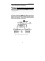
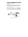
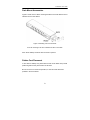
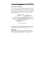
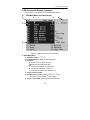
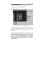
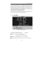
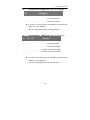
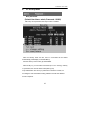
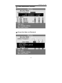
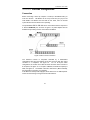
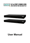
Switch 4 PORT / 8 PORT / 16 PORT Contents Introduction Overview…………………………………………………..1 Features……………………………………………….…..2 Configurations……………………………………………..3 Installation Connection………………………………………..……….5 Power-up…………….…………………..………….……..7 Rack Mount Accessories……….…………………...……8 Operation Front Buttons……………………………...…...……..……9 OSD (On-Screen Display) Menu………………………..10 Hot-key Commands………………………………………20 Cascade Configuration Connection……………………………..…….……...……22 Change Configuration while Running………..…………25 Appendices Specifications…….…………………………………..……26 Troubleshooting……………………………………………27 The products are tested and complied with FCC, CE and VCCI standards for electromagnetic interference. KVM Switch User’s Guide ------------------------ Introduction Overview Thank you for your purchased our products, The KVM Switch allows you to access multiple computers from one keyboard, mouse and monitor without extra interface card or software. KVM installation is as easy as connecting cables between the KVM Switch and your computers. Operation is just pressing push button, key in hot-key command or operating through the function of user-friendly on-screen menu (available for models with OSD only: XXXXD series), it’s simple and easy. Serial Mouse Conversion (RS-232 Interface) The KVM Switch you can connect computers with PS/2 or serial mouse port and control all PCs use one PS/2 mouse from the KVM console port. (Computer side need a PS/2 to Serial port adaptor if connect to computer serial port). High Video Quality The KVM Switch supports VGA resolution up to 1920 x 1440 (Max., bandwidth 300MHz)* and DDC1/2B compatible. On-Screen Display (OSD) Menu (OSD models only: XXXXD) For 4 / 8 /16 Port For KVM Switch with built-in OSD menu, you can rename your computers, select to a computer from a menu, also configure settings, view the selected computer like: name, time interval setting, security function setting (lock/unlock, channel authorize setting, password), ...etc. * Dependants on the quality of testing monitor and VGA card, VGA cable, then both PC port and Console port can be distance up to 20 – 30 meter. 1 KVM Switch User’s Guide Features PC port supports both PS/2 and serial mouse (specify adaptor) Supports Microsoft IntelliMouse (Pro), Optical, Mouse Man, Wheel Mouse, Scroll Point and Serial Mouse,…,etc. Keyboard states automatically saved and restored when computer channel switching Hot-key functions available for easy access computers Single hot-key for channel left/right shift sequentially. (left/right Alt ) Auto-scan can automatically switch computers sequentially (OSD model can setting auto-scan conditions) Buzzer sound On/Off selectable Hot-key Scroll Lock/Caps Lock selectable Cascade configuration expands system capability (64 to 4096 PCs) Operating system independent, transparent to all applications, no any software or hardware add Plug and play system configuration Keyboard and mouse can be hot plugged at any time High VGA resolution 1920 x 1440 (Max. bandwidth 300MHz) PC port keep alive capability, KVM powering down and all PC will still keep active Hot-Key function Select and access computers Sequential channel shift (left-decrease, right-increase) Scan function and time interval setting (Non-OSD model) Buzzer sound On/Off selectable Hot-key Scroll Lock/Caps Lock selectable Extra function for On-Screen Display model Assign computers names for more easy to identify Identify and select computers by the names Programmable scan conditions and scan time interval Password security lock/unlock access (Default Name: admin. Password: 123456) Store all setting information to non-volatile memory User friendly OSD interface 2 KVM Switch User’s Guide Configurations Single KVM Switch Configuration For your system safety purpose, you must turn off all PCs and Monitor during the configuration After plug in KVM power adapter, connect a PS/2 keyboard, a PS/2 mouse and a multi-sync VGA monitor to the KVM CONSOLE port. After that, connect the KVM cables (keyboard, mouse and monitor) between the KVM PC ports and computers, as shown in figure 1. Figure 1: Single KVM Switch configuration 3 KVM Switch User’s Guide Cascade (Master/Slave) Configuration Master KVM unit: has a physical keyboard, mouse and monitor connected to its CONSOLE port, any PC port can connect computer or another KVM. Slave KVM unit: is a KVM Switch that has its CONSOLE port connected to the Master's PC port. First, plug the power adapter to the Master KVM. Then connect the console device and PC port link. You can connect a second and third level of one or more KVM Switches to any PC port of the Master KVM. Cascade configuration expands system ability allowing you to select computers connected to the Master or Slaves. There is only need a mouse, a keyboard and a monitor connected to the CONSOLE port of Master and its can directly operated by a user. After connected, KVM Switches automatically configure Master or Slave by themselves. Slaves can be mixed different KVM Switch models in cascade configuration, show as figure 2. Figure 2: A cascade KVM Switch configuration 4 KVM Switch User’s Guide ------------------------ Installation Connection For your system safety, please make sure all PCs and Monitor or other devices are powered down during the installation Console Device Connection First, plug the power adapter to KVM. Then connect the CONSOLE and PC. The monitor connected to the HD-DB-15 VGA port of a Master CONSOLE port. Connect a PS/2 mouse and a keyboard to the CONSOLE port respectively with a mouse and a keyboard marked as shown in figure 3. Figure 3: Master console connection 5 KVM Switch User’s Guide Computer Connection For computers using PS/2 mouse, connect the computer's mouse and keyboard cables to the KVM Switch’s PC ports marked with a mouse and keyboard respectively. Connect the computer's monitor cable to the HD-DB-15 VGA connector. As shown in figure 4. Figure 4: Master computer connection For computers using serial mouse, connect the DB-9 to mini-DIN-6 adapter (supplied from manufacturer or agent) to the computer serial port, then connect KVM cable from the mouse adapter to KVM Switch, see Figure 5. Figure 5: Adapter and serial mouse connection Note: you can ask your agent or manufacturer for this mouse adaptor. 6 KVM Switch User’s Guide Initial Power-Up Process Make sure all computers and KVM Switches are powered down during installation. You must power up the Master KVM Switch before turning on any other devices. For single KVM Switch: 1) Apply a power adapter to the Master. (after cables connected) 2) Turn on computers. For cascade: 1) Apply a power adapter to the Master. 2) Apply power adapters to all Slaves. 3) Turn on computers. Note: You may hot plug any powered-down computer and Slave KVM at any time after initial power up process completed. Hot Plug Capability Master Console Devices Replacement You can replace a keyboard or mouse of the Master CONSOLE port at any time without powering down the Master KVM. PC Port Hot Plug and Hot Swap You can plug in or out of PC port or swap PC port at any time without powering down the KVM. Note: Some PC was not support PnP configuration and it will need to rebooting after Hot swap. In case, some devices need to rebooting or software driver initial, you may press the Reset button in the KVM front panel to re-start the KVM initial process. 7 KVM Switch User’s Guide Rack Mount Accessories Figure 6 shows how to attach mounting brackets to the KVM Switch unit for standard 19-inch rack cabinet. Figure 6: Attaching rack mount bracket It can be mounting in the rack cabinet front side or back side. Note: Some desktop model the rack mount kit is optional Rubber Foot Placement If user wants to desktop use, please stick the four round rubber feet (in small plastic bag with the unit) to the bottom of the KVM. But do not use it for rack mount operation, it could be cause dimension problem in the rack cabinet. 8 KVM Switch User’s Guide ------------------------ Operation Front Panel Push Buttons You may select a computer by pressing the front panel push button directly, or press hot-key or activating the OSD menu(for models with OSD only). The front panel indicators(orange or red) will changes to the selected computer port and the connected computer power on the green indicator will turn on. When KVM is in Auto Scan mode the selected indicator will flashes (orange or red) Figure 7: Front panel indicator If the computer was support 'keyboard/mouse power up' function, (press certain keys or mouse buttons to startup the computers). The front panel green indicators will light all the time even the computers are 'off'. KVM RESET In case the Device replacement or change of configuration cause some problem, pressing the front-panel Reset push buttons for re-configure the system without turning either the KVM Switch or any computer off. 9 KVM Switch User’s Guide OSD (On-Screen-Display) Operation 4 port w/OSD, 8 port w/OSD, 16 port w/OSD (XXXD Series) z 1 OSD Main Menu for Administrator 2 3 4 5 6 Figure 8: Administrator OSD screen illustration A. OSD Main Menu 1. KVM layer number: 1st, 2nd, 3rd 2. PC name (define by user): 31 characters (Max.) 3. PC Status: ; Buzzer sound on (above the STA)s Buzzer sound off (above the STA) s L Locked port indication, normal is blank ¡ Indicating the computer is power on s Indicating the channel scan function is on 4. Current channel number. 5. Cascade channel number: display cascade 2nd, 3rd layer Connected channel number, 1st layer is blank 6. Only for 16 port OSD. (Next page) other model is blank 10 KVM Switch User’s Guide B. Function control Menu F3: User Lock function will available when F5 Security is set ‘ON’ F5: Security function and user priority setting F6: PC port lock function (administrator only) ● OSD Main Menu for other user (1, 2, 3) Figure: User OSD screen illustration (F5 Turn ON first) For administrator by pressing the <Scroll Lock> key twice and <Enter>, you will see an OSD 'Main MENU' screen showing a menu of the computers with: channel number, names and other status and some function menu, please see figure 8. The channel of the currently selected computer is displayed in the top right corner and a highlighted pink bar in the PC name list, to the right of the PC name 'STA'. The sign ¡ is display if computer has power on and ready for selection (its corresponding front panel indicator is green), if the sign ¡ is blank, it has no power. OSD menu updates the sign ¡ when computer is activated. Use the <UP> and <DOWN> arrow keys to highlight a computer and the <ENTER> key to select it and leave OSD menu. Or, you may press <ESC> to exit OSD menu. 11 KVM Switch User’s Guide A plus mark (+) to the left of a name indicates the port is cascaded to a Slave; the number at the above of the channel number (left corner) shows the number of port the Master link, i.e. 8 means link from upper KVM port 8 (Master layer is blank). <ENTER> key brings you one level down and the screen pops up listing the names of the computers on that Slave KVM. The name of the Slave will be shown at the OSD menu. It is useful to group computers and still be able to see the group name. Press <R> will return to upper layer OSD menu. Press <ESC> key to exit OSD and to return to the selected computer; the computer name is also shown on the screen (banner). z F1: Setup Mode Figure: OSD setup screen All change is use left/right arrow key (← →) to select it. ■Scan Mode: Select – Scan selected channel. PC ON – Scan power on PC channel only. ■Scan Time: 5sec(Default) to 90sec., 5sec. a select step ■Banner Display Time: 5sec. (Default), 10sec., 15sec. and always on (∞). 12 KVM Switch User’s Guide ■Display Position: Menu – use four arrow key to move the OSD main menu to the desire position. Banner – use four arrow key to move the channel banner to the desire position. ■ Hotkey: Scroll – Scroll Lock become the Hotkey. Caps – Caps Lock become the Hotkey. ■ Sound: ON – Buzzer sound active (turn on) OFF – Buzzer sound disable (turn off) ■ Language: English (En) / Deutsch (De) / Francais (Fr), ● three countries. Position Adjustment Figure: Select the item to setup After into the banner Display Position the display will become: 13 KVM Switch User’s Guide z Channel Banner (Single Layer) (Max. 22 characters) ┬ ────┬────── │ └PC (Channel) Name └───────────── Channel (PC) number PC power on or change channel by OSD/Hot-key, this banner will display 5 sec. then disappear. User can change display time in the Setup Mode (F1). z Channel Banner (Multi-Layer) (Max. 22 characters) ┬ ┬ ┬ ────┬────── │ │ │ │ │ └─────── Channel (PC) number │ └─────── 2nd Layer Channel (PC) number └ PC (Channel) Name └───────────1st Layer Channel (PC) number PC power on or change channel by OSD/Hot-key, this banner will display 5sec. then disappear. User can change display time in the Setup Mode (F1). 14 KVM Switch User’s Guide z Channel Banner (Scan Mode) ─┬── ┬ ──┬────── │ │ │ └──────── Channel (PC) number └─PC (Channel) Name └───────────── Scan Mode z Stop scan: press any key. Banner will disappear when the scan is stop. F4: Rename (New Name: 31 characters Max) 15 KVM Switch User’s Guide z F5: Security Mode Entry Password: (Default User Name: admin, Password: 123456) After entry correct password, Security function is enabled. After the Security mode set ‘ON’, then F3 Lock Mode will be enable Automatically (it will display on the Main Menu). Also the Hot-key Lock function (H) will available. After security on, you can active lock function (F3 or <H> hot-key), until key in a password, the console will be locked (like log out) Only authorization user can key in password to unlock the console, but according the user authorization setting, different user will have different access computers. 16 KVM Switch User’s Guide ● Change Administrator Password: ● Change User Name and Password: 17 KVM Switch User’s Guide ● User PC Channel Authorization Setting ● F6 Lock Port 18 KVM Switch User’s Guide After PC port locked, “L” mark will show in the STA field, until unlock (Select F6 and key in password again, port unlock) z F3 Console Lock Mode Banner: After into the Security lock mode, this banner will display until Unlock The console device and KVM button will lock (no any function); the keyboard will just accept the correct password only. (press any key to into the unlock window) z Unlock Window: After key-in correct User Name and Password, the system will Unlock (leave the Security mode), screen will into the normal and all device are available to operating (according the authorization setting). If you forget the password, the only way to permanently disable the security function is use a universal password to unlock KVM. You need to key-in this unlock password to release your device and KVM, then you can restart everything. Universal password will let your KVM go back to default administrator password, Universal password: (Name: EZLINK, Password: EZLINK) 19 KVM Switch User’s Guide Function Control (Hot-key commands) Call OSD Menu (OSD model only) Pressing the <Scroll Lock> key twice and 'Space Bar' and <ENTER>, then the OSD 'Main Menu' will on the screen. (Or after <Scroll Lock> twice and press <ENTER> directly) ★Hot key can be change become<caps lock> Channel Select OSD: Use Up/Down arrow and <ENTER> to select the channel directly. z Hot-key: Pressing the <Scroll Lock> key twice then Key-in a channel number (1 to 16) and press <ENTER> z Left<Alt> or right <Alt> twice the PC channel will automatically shift left/right one channel (channel decrease / increase to next) while <Alt> enable. z <Alt> shif function default was off, pressing hot key twice then <Alt> and <Enter> you can on/off this funtion alternately. if buzzer was on, it will generates a beep for correct operating. Auto Scan OSD: Call OSD 'Main Menu' then press <F2>. z Hot-key: Pressing the <Scroll Lock> key twice then <S> and <ENTER>. Console Lock (OSD model only) OSD: Call OSD 'Main Menu' then press <F3>. (<F5>: Security Mode must be turn on first) z Hot-key: Pressing the <Scroll Lock> key twice then <H> and <ENTER>. 20 KVM Switch User’s Guide Console Unlock (OSD model only) OSD: Display the message only. z Hot-key: Pressing any key into the Unlock window then entry the correct User Name and Password, KVM and console device will unlock and back to normal operation. Setup Mode (OSD model only) OSD: Call OSD 'Main Menu' then press <F1>. z Hot key: Non Hot-key operating. Daisy Chain Layer Change (Channel Select) OSD: Call OSD 'Main Menu' then select channel and press <Enter> layer by layer. z Hot-key: Pressing the <Scroll Lock> key twice then <D>, number (1,2,3…. 16) and <ENTER>. If cascade 3 layer, you can select last layer directly, D2D5D7: layer 1 channel 2 links to layer 2 channel 5 then select layer 3 channel 7. Buzzer sound ON / OFF z Hot-key: Pressing the <Scroll Lock> key twice then <B>, buzzer sound will ON /OFF alternately. Hot-key Select OSD: Call OSD 'Main Menu' then press [F1] and select hot-key change. z Hot-key: Pressing correct hot-key twice the<K>, The hot-key will change to another one. (<Scroll Lock> or<Caps Lock>) 21 KVM Switch User’s Guide --------------- Cascade Configuration Connection Before connecting a device (a computer or a Slave) to the Master KVM, you must turn off them. The Master can be a any model and you just put one OSD KVM to the Master and Non-OSD for the Slave, then all cascade system will become full OSD function operating. The ports labeled "PC 1"~”PC 16” can be connected to either a computer or a Slave's CONSOLE port, as shown in figure 9. A power adapter with DC 9V/500mA output rating must be connected to the Master. Figure 9: Slave console connection The maximum number of computers controlled by a master/slave configuration with all 4-port switches is 64 with 16 Slaves and each Slave connects to 4 computers, see figure 10. For an all 8-port switch configuration, the number is 512 with 64 Slaves and each Slave connects to 8 computers, see figure 11. If a 16-port is a Master, the maximum capacity is 4096, see figure 12. The Master connects to 256 Slaves ( PC 1 to PC 16), and each Slave connects to 16 computers. If the Master is already OSD-equipped, all the Slaves are not OSD required. This is the extra saving of using this line of KVM switches. 22 KVM Switch User’s Guide Figure 10: Cascaded 4-port KVM Switch Figure 11: Cascaded 8-port KVM Switch 23 KVM Switch User’s Guide Figure 12: Cascaded 16-port KVM Switch For OSD model: After connection completes, you should call OSD menu to check if the Master recognizes the Slaves. A plus mark (+) is placed to the left of the channel name indicating the port is connected to a Slave not a computer. 24 KVM Switch User’s Guide Change Configuration while Running Devices at any PC port can be changed at any time after initial power-up. If you change any one of the “PC 1” to “PC 16” ports connection from a computer to a Slave or change Slave cascade port, or replace the devices of a port; the OSD will update this change when next time it is activated. [NOTE: Any new device, a computer or a Slave, must be turned off before it is connected to the Master.] Note : example for different model (front panel and back panel) 25 KVM Switch User’s Guide ------------------------ Appendices Specifications: Specifications X104L X108L X116L X104LD X108LD X116LD Computer port number 4 8 16 Cascade control PC Up to 64 Up to 512 Up to 4096 On-screen display (OSD) 104LD X108LD X116LD Front panel button control 4 8 16 number Hot plug-and-play Yes Hot-key control Rack-mount kit Yes Option Built-in Automatic OSD 5 ~ 90 sec., 5 sec. step scan interval Non OSD 5 ~ 250 sec., 1 sec. step OSD model only Programmable scan patter n Year 2000 Compliant Yes Cable length (Max) 30M (100ft) at CONSOLE VGA Max.2048 x 1536(300MHZ) 30M (100ft) at PC , DDC1/ DDC2B Computer keyboard PS/2 mouse PS/2, serial (with adapter) monitor HD-DB-15 male Console keyboard PS/2 mouse PS/2 monitor HD-DB-15 female H x W x D (mm) (in) size Power supply z 44x440x132 44x440x132 75x440x125 1.7x17.3x5.2 1.7x17.3x5.2 3.0x17.3x4.9 1U 1U 2U (9V DC, 500mA) You can mix different models in cascade applications. 26 KVM Switch User’s Guide Troubleshooting: Make sure that all cables are well seated. Check that keyboard/mouse cables are not swapped. Label and bundle the cables for each computer to avoid confusion when connected to the KVM Switch. Symptom Possible causes z No power to KVM z Loose connection z Monitor not multi-sync Keyboard error z Loose connection on boot z Keyboard failure No Monitor Screen PC port serial Mouse do not work Multi-function Mouse do not Work normally Keyboard strokes shifted z Incorrect serial mouse adaptor z Loose connection z Mouse do not set in PS/2 standard z The computer was in shifted state when last switched Incorrect configuration Or improper installation procedures Recommended solutions z Plug the power adaptor. z Reconnect monitor cable z Use multi-sync monitor z Make sure keyboard cables are Well seated z Change keyboard z Make sure use specify serial mouse adaptor z Reconnect cable/adaptor z Make sure the mouse is set in the PS/2 standard z Press both SHIFT keys down a couple of times z Make sure the slave’s CONSOLE is connected to Master’s PC port z Remove any possible power supply to the slave (unplug all cables), before connecting it to the Master KVM Auto z All PCs are off or only z Turn on computers Set Selected Scan Type in Scan does one PC is power on, not switch PC Scan mode set for OSD and determine which PC-ON only PCs is s mark selected, do it z Scan type is s mark in OSD. Press any key to abort Auto selected but no Scan mode then Press power-up PC is s mark <Scroll Lock> twice and <S>, selected in OSD. <Enter> to restart the Auto (screen blank) Scan Double OSD z Improper slave z Remove any possible images at connection procedure. power supply to the Slave cascade z Loose connection (unplug all cables), before configuration connecting it to the Master z Make sure cable is connect Well, slave console link to master PC port. Master/Slave Does not work 27 KVM Switch User’s Guide Use <F1>: Setup\Position to OSD menu is z OSD menu has fixed move OSD menu and banner not at the resolution and its size to proper position. proper position varies due to computer VGA resolution changes. Can not select z Improper Master unit z Only Master PC port can be connected to slaves. connection a computer z Connect slave CONSOLE connected to a z Improper slave unit port to PC ports of the Master connection slave z Only two level of slave units is z Too many levels of allowed. Pop up OSD again slaves to check if Master recognizes the slave connection. Look for plus (+) mark and the number in OSD menu. z Computers do not z Make sure a power adapter The KVM supply enough power. with minimum of 9V 500mA Switch fails to output rating is firmly function connected to the power jack. occasionally. Limited Warranty IN NO EVENT SHALL THE DIRECT VENDOR'S LIABILITY FOR DIRECT OR INDIRECT, SPECIAL, INCIDENTIAL OR CONSEQUENTIAL DAMAGES, LOSS OF PROFIT, LOSS OF BUSINESS, OR FINANCIAL LOSS WHICH MAY BE CAUSED BY THE USE OF THE PRODUCT EXCEEDS THE PRICE PAID FOR THE PDOCUDT. The direct vendor makes no warranty or representation, expressed or implied with respect to the contents or use of this documentation, and especially disclaims its quality, performance, merchantability, or fitness for any particular purpose. The direct vendor also reserves the right to revise or update the product or documentation without obligation to notify any user of such revisions or updates. For further information, please contact your direct vendor. All the brand names and registered trademarks are the property of their respective owners. 28 KVM Switch User’s Guide PP2-NC1000-003EN Printed Taiwan