1
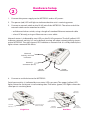
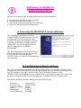
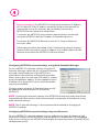
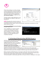
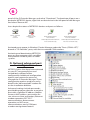
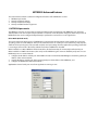
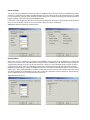
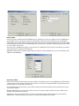
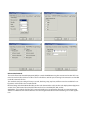
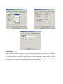
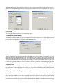
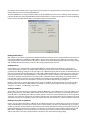
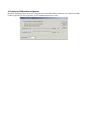
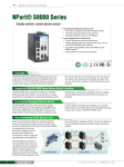
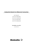
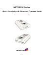
NETRS232 Series
Quick Installation & Advanced Features Guide
Rev. B05
1
Getting Started
Congratulations on your purchase of a StarTech NETRS232. NETRS232s connect serial
devices to Ethernet networks. Any serial device—POS equipment, factory machinery,
monitoring hardware, or security devices, for example—can send its information to the
NETRS232.The NETRS232 places the serial data in a TCP/IP wrapper and sends it out its
Ethernet port. Data moving the other direction, from the Ethernet side of the
NETRS232 to the serial device, undergoes the same process in reverse. StarTech
NETRS232s use industry-standard hardware interfaces and are supported in Windows®
2000, Windows® XP, Linux, and QNX.
With a NETRS232, you can:
•
•
•
•
•
•
•
Network serial devices
Make devices available to multiple users
Manage multiple serial devices from a single PC
Eliminate long dedicated serial runs
Stop using costly PCs as dedicated serial port servers
Remotely access and control serial devices
Eliminate long-distance phone-modem charges
Included with your package, you should have the following:
•
•
•
•
StarTech NETRS232
Power supply
Installation diskette
Quick Installation Guide
Please note! NETRS232 is factory pre-configured with passwords as follows:
Administrative password: admin
Port 1 password: port1
Port 2 password: port2
etc..
Before using NETRS232 you will need to unlock the unit using the
administrative password in order to configure the device's IP address and
other settings. We recommend changing the administrative password to
something other than the factory default for best security.
Port passwords can be removed or altered as needed, provided
administrative access is granted.
Hardware Setup
2
1. Connect the power supply to the NETRS232 and to AC power.
2. The power (red) LED will light to indicate that the unit is receiving power.
3. Connect a network cable to the RJ-45 jack of the NETRS232.The other end of the
network cable can be attached to either:
• an Ethernet hub or switch, using a length of standard Ethernet network cable
• a host PC directly, using an Ethernet cross-over cable.
Network status is indicated by two LEDs on the RJ-45 connector.The left (yellow) LED
indicates network activity. It is on by default, turning off when network activity occurs
at the NETRS232.The right (green) LED indicates a network link. It is off by default, but
lights when a network link exists.
Network
Activity and Link
indicators
Network
connector (RJ-45)
Power
indicator
Power
connector
4. Connect a serial device to the NETRS232.
Serial port activity is indicated by two status LEDs per port.The upper (yellow) LED
lights when the serial port is transmitting data.The lower (green) LED lights when the
serial port is receiving data.
Serial Tx
indicators
Serial Tx
indicator
Serial 2
connector
(DB-9 shown)
Serial connector
(DB-9 shown)
Serial Rx
indicator
Single Port
Serial 1
connector
(DB-9 shown)
Serial Rx
indicators
Dual Port
Software Installation
and Configuration
3
Software installation and configuration consists of the following:
A. Running the NETRS232 setup software
B. Configuring network settings
C. Activating and deactivating NETRS232 ports
D. Optional advanced port configuration
A. Running the NETRS232 setup software
The installation diskette has files to
install NETRS232 drivers on your PC and
to detect NETRS232 devices on your
network.To run the installation software,
insert the installation diskette and run
"Setup.exe".The Setup Wizard will ask
you to supply basic installation
information.
The Setup Wizard will finish by opening
the IP-Extender Manager. By default the
IP-Extender Manager will display
NETRS232 devices that it has detected on
your network.
B. Configuring network settings
The IP-Extender Manager displays NETRS232 information in a Windows Explorer-like
interface. Any NETRS232 devices that are discovered on your network are displayed in
the "IP-Extenders Near Me" branch of the "My IP-Extender Network" tree.
NETRS232 devices installed on your network will need unique IP addresses.These can
be set by using either the IP-Extender Manager, a web browser, or a Telnet client.
The factory default network settings for the NETRS232 are:
IP address:
Subnet mask:
Gateway address:
Name:
Workgroup:
DHCP detection:
192.168.0.35
255.255.255.0
0.0.0.0
[empty]
[empty]
disabled
4
Before Proceeding: The NETRS232 is factory preset with an IP address
of 192.168.0.35. If this IP address cannot be used on the network (it
may already in use, for instance), do not initially connect the
NETRS232 to the network. Instead, either:
1) connect the NETRS232 to a network segment that is not already
using the NETRS232 default IP address for another device or,
2) connect the NETRS232 directly to a host PC using an Ethernet
crossover cable.
Follow the procedure described in the "Configuring network settings"
section of this manual to set the IP address to a usable address for the
network onto which the NETRS232 will be installed.
Configuring NETRS232 network settings using the IP-Extender Manager
To set a NETRS232's network settings using the IPExtender Manager, right-click on it in the IP-Extender
tree and select “Properties”. If the NETRS232 is
accessible on the network, a dialog will open that
allows you to give it a new name, IP address, subnet
mask, and gateway address. If your network assigns
IP addresses using a DHCP server, DHCP detection
can also be enabled.
Changes made using the IP-Extender Manager will
be updated to both the local PC and to the
NETRS232.
NOTE: Changing the network settings of a NETRS232 device may make that device
unavailable to other stations that have activated a connection to that device using
older network settings.
NOTE: The IP-Extender Manager is the recommended method of changing all
NETRS232 settings.
Configuring NETRS232 network settings using a web browser
To set a NETRS232's network settings using a web browser, open the browser and
enter the IP address of the NETRS232 into the browser's location bar.The embedded
web server running on the NETRS232 will display the opening screen of the NETRS232
configuration menu.
5
Choose the setting you wish to change.
In the configuration screen that appears,
and enter the network settings you wish
for that NETRS232 device. Once the new
values are entered and accepted, the
NETRS232 will reboot to implement the
new network settings.
Changes made using a web browser will
be updated to the NETRS232 but not to
the local PC.
NOTE: Changing the network settings of
a NETRS232 device may make that device
unavailable to other stations that have activated a connection to that device using
older network settings.
Configuring NETRS232 network settings
using a Telnet client
To set a NETRS232's network settings
using a Telnet client, open a Telnet
session to the IP address of the link
whose settings you want to change.
Details on Telnet connection can be
found in the “telnet.pdf” file on the
Installation diskette.
C. Activating & Deactivating NETRS232 ports
NETRS232 ports that have been detected
as existing on the network are not
initially activated for your PC.To access a
NETRS232 port it must be activated.You
may wish to activate on a given
computer some, all, or none of the
NETRS232 ports that are available on the
network.To activate a particular port,
right click on the port where it is displayed in the right panel of the IP-Extender
Manager, and select "Activate".To activate all ports on a particular NETRS232 device,
right click on that device in the left panel of the Manager and select “Activate All”.
Before activation, NETRS232 ports only appear under the "My IP-Extender Network"
branch of the IP-Extender Desktop. Once they have been activated for a local system,
they will also appear under "My Computer" in the IP-Extender Manager.
To deactivate ports individually, right-click on the port where it is displayed in the right
6
panel of the IP-Extender Manager, and select "Deactivate".To deactivate all ports on a
particular NETRS232 device, right click on that device in the left panel of the Manager
and select “Remove All”.
Icons depict the states of NETRS232 devices and ports as follows:
Device available
on the
network
Device not
available on the
network
Under “My Computer”:
Port available
Under “My Computer”:
Port not available
Under “My Ether Link Network”:
Port activated locally
Under “My Ether Link Network”:
Port not activated locally
Activated ports appear in Windows’ Device Manager under the "Ports (COM & LPT)"
branch as "IP-Extender" ports, with their associated COM numbers.
Activating and deactivating NETRS232
ports on one computer does not affect
the operation of those ports on other
systems.
D. Optional advanced port
configuration
NETRS232 ports that have been activated
on your PC can generally be used
immediately without further
configuration. Additional configuration
options can however be accessed
through the IP-Extender Manager.These
configuration options are discussed in
detail in the “advanced.pdf” readme file
on the Installation diskette.
Advanced settings include passwords;
port binding options that can associate a
port with a specified IP address, NetBios
name, or MAC address; port modes for
raw server or client connection, Ethernet
modem operation, RFC 2217
communications, data connect
operation, or RAS server
communications; and a COM port
number reassignment feature.
NETRS232 Advanced Features
This document describes the advanced configuration features of the NETRS232. It covers:
1.
2.
3.
4.
NETRS232 port modes
Virtual port (driver) settings
Virtual port (driver) bindings
Virtual port COM number assignment
1. NETRS232 port modes
The NETRS232 converts serial port data to and from TCP/IP packets over Ethernet. Each NETRS232 port exchanges
TCP/IP packets on its own unique TCP port (called the "Local Port" in the Properties dialog box). Each serial port on an
NETRS232 device can be configured independently to perform this conversion in one of eight modes:
Driver Mode (Default mode)
This mode enables the physical port of a NETRS232 to communicate directly with the serial port API of a supported
operating system as a local COM port. In this mode, authorized users can set bits per second, data bits, parity, stop bits,
and flow control port-by-port, or the port will accept its serial port settings from the application/operating system that
is accessing it. Driver mode is the factory default mode when a NETRS232 is installed.
When installed on a LAN, a NETRS232 in Driver Mode has all the functionality of an internally installed serial port.
When installed on a WAN or the Internet, the serial port of a NETRS232 gains enormous flexibility and power. To use a
NETRS232 port on a remote network:
1.
2.
3.
configure the IP address and TCP port of the WAN connection in the IP-Extender Manager to match the gateway IP
address of the remote network,
map the IP address and TCP port of the remote gateway to the IP address of the NETRS232, and
configure the NETRS232 itself for Driver Mode.
Applications: General serial port access from applications running on a PC.
Raw Server Mode
This mode is used to establish a raw TCP connection to a NETRS232 port. The physical port on the NETRS232 is made
available as a network resource with a specified IP address and port number. In this mode, authorized users can set bits
per second, data bits, parity, stop bits, and flow control port-by-port, to match the requirements of the Data Terminal
Equipment (DTE) connected to the physical NETRS232 port.
Control lines can be triggered by the TCP connection being established. Under the "Signal Settings" tab shown below,
the user can set how the control lines are to react when a TCP connection is established.
Applications: Remote monitoring, security systems.
Raw Client Mode
This mode is used to establish a raw connection to the NETRS232. The physical port on the NETRS232 is configured to
initiate a connection to a pre-defined IP address and port number, specified by an authorized user of that port in the
"Target Settings" dialog box. In this mode, authorized users set bits per second, data bits, parity, stop bits, and flow
control port-by-port, to match the requirements of the Data Terminal Equipment (DTE) connected to the physical
NETRS232 port. Operating as a client, the NETRS232 will open a connection to the target IP address and port when it
detects one or more of the following line conditions: data, DSR, CTS, RI, or CD. Users can configure which of these triggers will be in effect for any NETRS232 port set in this mode in the "Connection Control" dialog box. "Signal Settings"
are also settable by the user, as described in Raw Server mode.
Application: Remote control.
RFC2217 Mode
Users who want to communicate with a NETRS232 across gateways or routers can configure a port on a NETRS232 to
operate in RFC 2217 mode, allowing serial port configuration commands and serial data to be sent to a NETRS232
using the RFC 2217 framework for serial port control over Telnet. For those not familiar with RFC 2217 (the Telnet COM
Port Control Option), the text of the actual RFC (Request For Comments) is available at www.faqs.org/rfcs/rfc2217.html
or at any number of other sites.
This mode opens a NETRS232 port when a TCP connection is established to the "local port". Port settings are embedded in data stream in accordance with RFC 2217.
Applications: UNIX systems and other platforms that have RFC 2217 Telnet capability can access and control the serial
COM port of the NETRS232.
Data Connect Mode
Data Connect mode combines Raw Client mode and Raw Server Mode. In this mode, the NETRS232 will either initiate
a TCP connection when activity is detected at the serial port, or it will receive TCP packetized serial data from the network port when an outside client connects to it.
The configuration parameters for this mode combine all the parameters found in Raw Client and Raw Server modes
(see above for details).
With two NETRS232s in this mode placed "back to back," the connection between them becomes in effect a cable
extender over an Ethernet connection.
Applications: Data connect mode provides a serial-to-serial communication link that would not be practicable to
implement as a directly-wired link; it can replace serial cables with an Ethernet connection.
Ethernet Modem Mode
This mode allows Data Terminal Equipment (DTE) to control the NETRS232 using the conventional modem "AT" command set. In this mode, a DTE user is able to "dial" an IP address and TCP port. Incoming TCP connections are handled
under AT command set rules.
The standard serial port settings for bits per second, data bits, parity, stop bits, and flow control are available for configuration, and should be set to match the DTE.
Modem settings include ECHO Enabled (E1), Result Codes Format Verbose (V1), Result Codes Display Return (Q0), Auto
answer (S0=1), DSR Control (&S1). Modem DTR control can be set to &D0, &D1, &D2, or &D3.
Applications: To provide the standard "AT" command interface to user applications that wish to communicate with
devices in an Ethernet environment. Remote console management that looks for AT interfacing can use this application.
RAS Server Mode
Windows-based devices that have Remote Access Services (RAS) client capability but are not equipped with a direct
network interface can access the network through a serial port using the Point-to-Point Protocol (PPP).
The serial port of the RAS client device is attached to the serial port of the NETRS232, configured in RAS Server mode.
The RAS negotiations are conducted between the RAS client and the NETRS232 RAS server.
In the initial negotiations between the RAS client and the NETRS232, an IP address (configured by user) is assigned to
RAS client, which is used for all Ethernet communications related to the RAS client.
Applications: Windows CE embedded systems, Palm type units, or other portable data acquisition devices that may
need access to a TCP/IP-Ethernet environment, and have PPP capability, but do not have a Ethernet port, can be connected to the serial port of a NETRS232.
Disabled Mode
This mode simply disables a port; it has no configuration settings.
2. Virtual port (driver) settings
The NETRS232 virtual port allows a serial port on a NETRS232 to be used in same manner as a local serial port when the
port is configured in Driver Mode (described above). In this state, the driver for the virtual port converts local serial
port accesses into TCP/IP packets to be exchanged with NETRS232 ports.
Polling Limit
Setting a polling limit for the virtual port driver allows the NETRS232 to support high-speed connections. The serial
port is constantly polled for new data. Polling stops when number of consecutive polls with no new data reaches the
polling limit parameter specified in the dialog box. Since polling introduces network traffic, this parameter should be
set as low as possible without introducing a lag to the connection. To reduce network traffic, reduce the polling limit;
to reduce lag, increase the polling limit. Interactive applications (such as typing) or applications that exchange bursts
of data should use a lower polling limit. Applications with a constant high data rate should use a higher polling limit.
Compatibility Mode
The NETRS232 virtual port normally operates in high performance mode. Compatibility mode supports applications
that require a more accurate simulation of a local serial port. The need for Compatibility mode is indicated when data
being sent to the remote serial port is lost or sent repeatedly.
3. Virtual port (driver) bindings
Background
Activating a NETRS232 port in effect creates a "virtual" driver port that is associated with a particular physical serial
port on a particular NETRS232. When a driver virtual port is opened, a connection must be established to the appropriate NETRS232. In normal operation, that connection is made to the IP address assigned to the NETRS232 at the time
the activation was created. However, on many Ethernet/IP networks, the IP address of individual devices may change
(for example, when a DHCP server assigns addresses). This address reassignment will cause virtual ports to fail or make
unintended connections to unintended NETRS232s.
Therefore, NETRS232s are designed with the ability to "find" a NETRS232 port based on a "binding". A port binding is a
network identification of the target NETRS232 that must match before a driver port will initiate a connection. Bindings
may be made to the MAC address, Name, or IP address of the associated device.
Binding to MAC Address
MAC addresses are unique and permanent identifiers for Ethernet devices, and are assigned to devices when they are
manufactured. Binding to a NETRS232's MAC address ensures that a virtual port always makes a connection to that
same physical device, even if the device's IP address or Name have changed. Binding to MAC address provides security
and reliability. Virtual ports will only connect to that single particular physical device.
Binding to Name
Device Name is a 15-character field assigned by the NETRS232 system administrator. Binding a virtual port to a
device's Name will ensure that a connection will be made to an actual port if a device can be found with the name
specified in the "Bindings" dialog box. This port may be on a different physical device from the one with which the virtual port was initially communicating (that is, a device with a different MAC address), or it may be a port on the same
physical device but with a changed IP address, or both. Binding to a device's Name provides reliability and dynamic
connections. Virtual ports will connect to the device with a name that matches the binding. If a particular device is
replaced with a new one with the same assigned Name, the virtual port will establish the connection. Also, Names can
be reassigned at any time to cause client PCs to connect to new devices without being reconfigured.
Binding a virtual port to a Name allows that virtual port to be identified on the network with a more representative
mnemonic than an IP address or MAC address. For example, a security system might name its virtual port targets
"Camera1", "Camera2", "CardReader6", and so forth.
Binding to IP Address
The IP address of a network device is assigned by either the NETRS232 system administrator or through a DHCP server.
Binding a virtual port to an IP address will force that virtual port to attempt a connection to any device with that particular IP address only. Binding to IP address provides dynamic connections. Device IP addresses can be reassigned at
any time to cause client PCs to form new connections without being reconfigured. Note: when no bindings have been
stipulated, a virtual port is implicitly bound to an IP address because such an address is required to make a connection.
Binding to more than one parameter
Usually, only one degree of binding is sufficient for an individual virtual port to achieve the goals of robust communication and flexibility. It is however also possible to bind a virtual port to more than one parameter. Doing so requires
careful consideration of the implications of maintaining connectivity. If multiple bindings are selected for one port, all
individual binding parameters must match for a connection to be made. For example, enabling both IP address and
MAC address bindings for a virtual port would cause that virtual port to find a particular physical device by MAC
address, but make a connection only if the device's IP address also matched the binding setting.
4. Virtual port COM number assignment
By default, an NETRS232 virtual serial port is assigned to the next available COM number when it is activated. This COM
number assignment can be reassigned to any unused COM number from 1 to 256.
Technical Support
The following technical resources are available for this StarTech.com product:
On-line help:
We are constantly adding new information to the Tech Support section of our web site.
To access this page, click the Tech Support link on our homepage, www.startech.com.
In the tech support section there are a number of options that can provide assistance
with this product.
Knowledge Base - This tool allows you to search for answers to common issues using
key words that describe the product and your issue.
FAQ - This tool provides quick answers to the top questions asked by our customers.
Downloads - This selection takes you to our driver download page where you can
find the latest drivers for this product.
Call StarTech.com tech support for help:
USA/Canada: 1-800-265-1844
UK/Ireland/Europe: 00-800-7827-8324
Support hours: Monday to Friday 8:30AM to 6:00PM EST (except holidays)
Warranty Information
This product is backed by a one-year warranty. In addition, StarTech.com warrants its
products against defects in materials and workmanship for the periods noted, following
the initial date of purchase. During this period, the products may be returned for repair, or
replacement with equivalent products at our discretion. The warranty covers parts and
labor costs only. StarTech.com does not warrant its products from defects or damages
arising from misuse, abuse, alteration, or normal wear and tear.
Limitation of Liability
In no event shall the liability of StarTech.com Ltd. and StarTech.com USA LLP (or their
officers, directors, employees or agents) for any damages (whether direct or indirect,
special, punitive, incidental, consequential, or otherwise), loss of profits, loss of business,
or any pecuniary loss, arising out of or related to the use of the product exceed the
actual price paid for the product.
Some states do not allow the exclusion or limitation of incidental or consequential
damages. If such laws apply, the limitations or exclusions contained in this statement
may not apply to you.