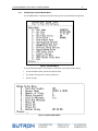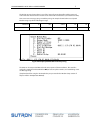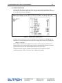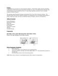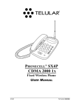
1
TELULAR SX4E PHONECELL
WITH THE
8210 SPEECH MODEM
APPLICATION NOTE
September 2004
Prepared by:
Integrated Systems Division
The Sutron Corporation
21300 Ridgetop Circle
Sterling, VA 20166
Copyright© 2004 Sutron Corporation
TELULAR PHONECELL WITH THE 8210 SPEECH MODEM
i
TABLE OF CONTENTS
1. Overview ............................................................................................................. 1
2. Equipment and Options................................................................................ 2
3. Equipment Connections and Specifications ......................................... 2
3.1 Equipment Specifications........................................................................................................................ 3
3.1.1 CELLULAR MODEM FEATURES ...................................................................................................... 3
3.2.1 8210 Speech Modem Features...................................................................................................... 3
4. Cellular Modem Activation .......................................................................... 5
5. Speech Modem Setup.................................................................................... 6
6. 8210 Data Logger with Speech Modem Setup..................................... 7
6.1 Speech Modem Menu Setup................................................................................................................. 7
6.2 Sample Sensor Setup .............................................................................................................................10
7. Troubleshooting ............................................................................................11
TELULAR PHONECELL WITH THE 8210 SPEECH MODEM
1
1. Overview
The Telular PhoneCell SX4e is a tri-mode (TDMA/PCS/AMPS) cellular modem capable of supporting
Voice, FAX and Data operation. Voice operation is supported in all modes.
This makes the Telular PhoneCell SX4e best suited for applications requiring voice reports.
The Telular PhoneCell SX4e is a fixed wireless terminal (FWT). These FWT devices are based on Telular’s
proprietary RJ-11 to cellular interface technologies. This allows connection to the Sutron 8210 Speech
Modem using a standard RJ-11 cable connection.
Data operations with the Phonecell are dependent on several factors including your local cellular
service provider. Because most TDMA and PCS networks do not support digital fax and data services,
AMPS 800 MHz networks or AMPS 800 MHz channels on TDMA 800 MHz networks are used for fax and
data services. Contact your local cellular dealer or service provider to determine the availability of an
AMPS analog network. Other cellular products are best suited for data only applications.
The Sutron 8210 Speech Modem will allow voice communication with the 8210 Data Loggers. User’s
may dial in and obtain real-time readings via voice reports. Voice reports of alarm conditions defined
by the user can be transmitted to up to three different phone numbers by the 8210 Speech Modem
dialing out using the SX4e Phonecell FWT.
The following sections present:
The required equipment and options
Equipment cable connections and equipment specifications
Instructions for setting up cellular service and the SX4e FWT
Instructions for setting up the 8210 Speech Modem
Complete instructions for programming the 8210 can be found in the 8210 Users Manual. A copy this
manual is available at:
www.sutron.com/DownloadsUpdates/8200_8210Manuals.ZIP
TELULAR PHONECELL WITH THE 8210 SPEECH MODEM
2
2. Equipment and Options
The application requires the following equipment:
Part Number
Description
1
8210-3014-1A
8210 Data Logger with Speech Modem
2
8111-7000-1
Phonecell SX4e FWT with RJ-11, serial cables, battery power cable
PHONECELL® is a register trade mark of the Telular Corporation.
The Telular SX4e is supply with an eight (8) inch ONMI antenna intended for interior mounting. The
antenna input connection of the SX4e is a TNC female connection. This antenna is suited for use in
areas with strong cellular service signal. The following antenna options are available:
8111-1168-1 Antenna, YAGI, 800MHz, 6db w/20ft RF cable
8111-1168-2 Antenna, ONMI, Dual Band 800-1900 MHz, Xdb w/20ft RF cable
8111-1168-3 Antenna, YAGI, 1900MHz, 6db w/20ft RF cable
Each includes a coaxial surge protector and 3ft jumper cable to interface from the protector to the
SX4e FWT.
3. Equipment Connections and Specifications
The equipment configuration consists of an 8210-3014-1A Data Logger with Speech Modem option
and a SX4e cellular FWT.
The cellular modem transceiver will be connected to the 8210 Speech Modem using an RJ-11
connection. The cellular modem has an RJ-45 receptacle, connect a cable from this port to the RJ-11
receptacle of the Sutron RJ-11 module that comes with the 8210 Speech Modem. This RJ-11 module
connects to the Phone T and R inputs in the 8210 terminal block.
RJ-11 Connection
Figure 1 8210 connects to the SX4e FWT via a standard RJ-11 phone cable.
TELULAR PHONECELL WITH THE 8210 SPEECH MODEM
3.1 Equipment Specifications
3.1.1 CELLULAR MODEM FEATURES
Exceptional voice quality with echo cancellation and digital voice/data privacy
DTMF and pulse-dial capability
External linear power supply
Built-in signal strength indication and self monitoring capabilities for user diagnostics
Easily programmed using ordinary telephone
3.1.1.1 Specifications
Air Interface Standard
GSM
TDMA
PCS
AMPS (ANALOG)
Transmit Power
Maximum 600mW
Operating Voltage
12VDC (11.5 to 26 VDC)
Environment
Operating temperature range: -10C to +50C
Storage Temperature Range: -25C to +65C
Humidity 5% to 95%
LED Indicators
Power Status
Cellular Status
FWT Status
Connectors
RJ-45 interface jack for voice (Accepts RJ-11 phone line connector)
3.2.1 8210 Speech Modem Features
Provides voice report of sensor values
DTMF (Dual Tone Multi-Frequency) Decode
Speech menu options using DTMF signals
3
TELULAR PHONECELL WITH THE 8210 SPEECH MODEM
4
-40C to +85C extended operating temperature
3.2.1.1 Specifications
Operating Temperature -40°C to +60°C
Electronics Protected to 3000 Volt (peak), 500 Joule transient phone line surges from tip to ring,
tip to ground, and ring to ground. Low power standby mode. Receiver sensitivity-45dBm.
Receiver dynamic range 36dBm (-9dBm to -45dBm)
Standard Interface Telephone 2 wire to RJ-11 modular jack
Mode Capability Full duplex over public switched telephone network (PSTN). Bell 212A (1200
pbs) and Bell 103 (300 bps). CCITT V.22 (1200 bps) and V.21 (300 bps)
Answer Mode Ring detect. Auto-baud rate detection. 2225 Hz Answerback Tone. 30 second
timeout if baud rate training sequence not complete
On-Hook/Off-Hook On-hook call termination after autoanswer or auto-dial timeout
With Call Termination 30 seconds (programmable) of data inactivity. System reset. Power-up
initialization.
Applicable Standards Phone Line Interface meets or exceeds the following standards:
o
U.S.Federal Communications
o
Commission (FCC). Rules and
o
Regulations Part 68
o
Canadian Department of
o
Communications - Standard CS-03.
o
Electronic Industries Assoc. (EIA) Standard RS-496
TELULAR PHONECELL WITH THE 8210 SPEECH MODEM
5
4. Cellular Modem Activation
Selection of a cellular service provider involves several considerations including: signal strength at the
remote site, system type (TDMA\PCS\AMPS), and service plan cost. Most established services started with
AMPS and are required to maintain this service. Digital data service may be available and may be at a
lower cost. Consult your service providers in the area of the station to determine the best selection. Once a
service provider has been selected and service has been initiated, the SX4e needs to be programmed for
the system.
The SX4e is programmed with an ordinary tone-dial (DTMF) telephone, which is sometimes referred to as
POTS (Plain Old Telephone Service) phone. The following steps provide a typical programming setup.
Consult the Phonecell SX4e User Manual for the detailed programming instructions. Except for the Mobile
Identification Number (MIN) discussed below, the factory defaults will work in most cases. Be certain to
review the programming steps given below with your service provider or have your service provider
program the Phonecell.
The exact programming may vary from model to model, refer to Telular Phonecell User Manual sent with
the unit for final instructions.
Before you begin programming, connect the antenna, plug in the power, and connect a tone-dial (DTMF)
telephone.
1) Pick up the POTS telephone handset and listen for a tone (either a steady dial tone or a beeping noservice tone).
2) Press: # * 0 * 1 2 3 4 4 3 2 1 #
The tone will change to a different, steady "Programming" tone and the bottom LED indicator on the
Phonecell will blink alternately RED and GREEN to indicate that you're in programming mode. You
now have two minutes to start the programming steps.
3) Press: # * 1 * <MIN> #
This key sequence is used to enter your 10-digit telephone number (Mobile Identification Number,
or MIN). If you enter the number incorrectly, you'll hear 3 short tones followed by the programming
tone. If correct, you'll hear the programming tone again. If the MIN phone number value is not 10
digits, it is considered invalid and the FWT will not update or store this value; the currently stored
value will remain.
Note – With the instigation of phone number portability, user phone number may be different from the
MIN. Make certain the service provider gives you both the user phone number and the MIN.
4) Press: # * 5 * <SID> #
This key sequence is used to enter the 1- to 5-digit System Identifier, or SID. This information
identifies your cellular service company. If you enter the SID incorrectly, you'll hear three short tones
followed by the programming tone; if correct, you'll hear the programming tone again. If the SID value
is not in the range of 0 to 32,767, it is considered invalid. The factory default is 69.
5) Press: # * 4 * <paging channel> #
This key sequence is used to set up your 1- to 4-digit initial paging channel. When you turn on your
Phonecell, this channel helps the service provider find you-and viceversa. If the paging channel is not
in the range of 1 to 1023, it is considered invalid.
NOTE: channels 800 to 990 are invalid. The factory default channel setting is 333.
6) Press: # * 7 * <band order> #
TELULAR PHONECELL WITH THE 8210 SPEECH MODEM
6
This key sequence is used to enter the band order. The band order value is a series of digits between
1 and 2 that must be at least 1digit and not more than 2 digits long. The following table describes the
relationship between the band order digits and EIA/TIA-136 system/band assignment:
Band Order Digits EIA/TIA-136
1 System A (800 MHz)
2 System B (800 MHz)
3 Band A (1900 MHz)
4 Band B (1900 MHz)
5 Band C (1900 MHz)
6 Band D (1900 MHz)
7 Band E (1900 MHz)
8 Band F (1900 MHZ)
If the band order values are not in the range of 1 to 8, or there are less than 1 or more than 8 digits, the
entry is considered invalid. The factory default is 3 4 1 2 5 6 7 8.
7) Hang up the phone. The flashing LED indicator will become solid GREEN.
Phone Number Setup is complete.
5. Speech Modem Setup
The 8210-3014-1A is shipped from the factory with the Speech Modem installed and the 8210 configured
as a Speech Modem unit. Users can purchase Speech Modem modules to be added in the field. The part
number for this module is 8200-3000-3 and includes:
Speech Modem Module
Interface Cable
RJ-11 receptacle with 6 inch phone cable
Mounting hardware (screws and washers)
The typical installation would place the Speech Modem module in the upper option location of the
8210. The interface cable would be connected to the cable header labeled J5 (nearest the edge of the
8210 Microprocessor module). When connected to the J5 header, the S1 DIP switches on the 8210
Microprocessor board need to be set as:
SW3 CLOSED
SW4 OPEN
(Switch settings the 8210 are described in Chapter 11 of the 8210 Operations Manual.)
TELULAR PHONECELL WITH THE 8210 SPEECH MODEM
7
6. 8210 Data Logger with Speech Modem Setup
This section presents the setup steps that enable the 8210 to use the Speech Modem. An example
setup of one sensor input configured to use the Speech Modem is included.
(Complete details for setting up the Speech Modem are presented in the Modem Setup section of
Chapter 4 of the 8210 Operators Manual.)
6.1 SPEECH MODEM MENU SETUP
The 8210 unit requires the following minimum setup to use the Speech Modem:
Configure the Speech Modem Menu
Configure a sensor in the ALARMS Menu
The Speech Modem will also operate in the data mode when used with the Phonecell unit and AMPS
service is available. If data access is planned it is highly recommended to do the following additional
setup steps:
Set a phone password in the Speech Modem Menu
Set the Enter Key Required mode to ON in the EEROM Menu
Failure to do this last step can lead to loss of the 8210 setup configuration due to a noisy or poor
quality phone connect.
TELULAR PHONECELL WITH THE 8210 SPEECH MODEM
6.1.1
8
Configuring the Speech Modem Menu
The 8210 Main Menu is displayed below. Enter M to go to the Speech Modem Setup Menu.
Figure 2 8210 Main Menu
The Speech Modem Menu is shown below. A minimum setup would include setting:
the Answer Mode (Voice, Voice & Data, Data & Voice)
the number of rings before answering (default, 1)
Dial-In message
Figure 3 Speech Modem Menu
9
TELULAR PHONECELL WITH THE 8210 SPEECH MODEM
The Dial-In message shown above is one of the “canned” reports that will speak the name and
value of the last measured value of each sensor enabled for “current data” (see Section 6.2 below).
Users can create a message using a vocabulary string. An example shown below uses a Speech
Modem string to speak the following message:
Welcome
to
the
Sutron
82
10
182
2
:173
:170
82
10
Figure 4 Example Speech Modem Vocabulary String
The 8210 can be setup to Dial-Out and make voice reports of alarm conditions. This would be
enabled by setting the Dial-Out Enable to ON, at least one phone number, and establishing a Dialout Message string.
(Complete details for using the 8210 vocabulary are presented in the Modem Setup section of
Chapter 4 of the 8210 Operators Manual.)
TELULAR PHONECELL WITH THE 8210 SPEECH MODEM
10
6.2 SAMPLE SENSOR SETUP
The last step in this example setup shows how a sensor is set to enable “Current Data” to be
included in the canned “Liv” report. This is done using the Alarm Sensor Options Menu. This Menu
is accessed from the System Setup Menu.
Figure 5 Alarm Sensor Option Menu
The figure above shows that the sensor named Battery has Alarm Options Enable ON, with the
Alarm Phases set to 67 (battery) and 177, (volts). These settings will cause the Liv report to state:
“ Battery is 12.52 volts.”
Other settings in the Alarm Sensor Option menu can be used to set high, low, or ROC (rate-ofchange) alarms. These settings could be used to have the Speech Modem dial out to up to three
phone numbers and announce alarm conditions with current sensor values.
(Complete details for using the 8210 Alarm Sensor Option are presented in the System
Setup\Alarm Options section of Chapter 4 of the 8210 Operators Manual.)
11
TELULAR PHONECELL WITH THE 8210 SPEECH MODEM
7. Troubleshooting
Possible Problem
Checkpoints/Solutions
The modem answers, but the voice is of
poor quality(noisy)
Check cell phone coverage in the area.
The cell phone has 3 LEDS, they should all
be green.
The modem does not pick up, you obtain
a dead signal.
Check if the cell modem has 12V.
Check external battery, voltage should be
around 12VDC.
I can obtain voice messages from the
modem, but no data
Contact local cellular provider to see if this
feature is available