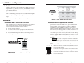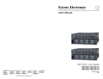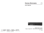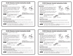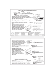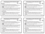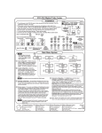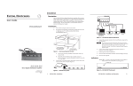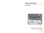
1
MSW 4V Switcher
OUTPUTS MSW 4V SDI
INPUTS
POWER
1.2V
.5A MAX
1
3
A
2
4
B
25 foot
cable
User’s Guide
CONTACT
1 2 3 4
KP 6 Keypad
Remote Control
Figure 3 — KP 6 application (with 5-pole captive
screw connector)
Operation
To select an input using the KP 6 Keypad Remote Control, press the
number key for the desired input.
Specifications
Power ............................................. None required
Temperature/humidity .............. Storage -40° to +158° (-40° to +70°C)/ 10%
to 90%, non-condensing
Operating ...................................... +32° to +122° (0° to +50°C)/ 10% to 90%,
non-condensing
Enclosure type .............................. Plastic
Approvals ..................................... CE
MTBF ............................................. 30,000 hours
Warranty ....................................... 3 years parts and labor
KP 6 Keypad Remote
Keypad Remote Controls
www.extron.com
Extron Electronics, USA
Extron Electronics, Europe
Extron Electronics, Asia
Extron Electronics, Japan
1230 South Lewis Street
Anaheim, CA 92805
USA
714.491.1500
Fax 714.491.1517
Beeldschermweg 6C
3821 AH Amersfoort
The Netherlands
+31.33.453.4040
Fax +31.33.453.4050
135 Joo Seng Road, #04-01
PM Industrial Building
Singapore 368363
+65.6383.4400
Fax +65.6383.4664
Daisan DMJ Building 6F
3-9-1 Kudan Minami
Chiyoda-ku, Tokyo 102-0074 Japan
+81.3.3511.7655
Fax +81.3.3511.7656
© 2002 Extron Electronics. All rights reserved.
68-694-01 Rev. A
Printed in the USA
07 02
Installation and Operation
Introduction
Pin
The KP 6 is designed to control MSW 4 Series, SW AV Series (4 and 6
input models only), SW VGA/Ars Series, and SW RGBHV/ A Series
switchers, or other Extron products with contact closure ports or
ports labeled as “Remote.”
1
The KP 6 is a contact closure remote for selecting the switcher’s input.
When a number key is pressed, the wire associated with that input is
momentarily shorted to ground, making the switcher switch to that
input.
5
6
9
Male
The KP 6 can control up to 6 inputs and requires no power.
Installation with a 9-pin D-sub connector
Brown
2
—
—
Not used
Not used
—
3
4
In#2
Input #2
5
Gnd
Signal ground
Black
6
In#3
Input #3
Orange
7
In#4
Input #4
Yellow
8
In#5
Input #5
Green
9
In#6
Input #6
Blue
—
Red
Some switchers, such as the MSW 4 Series, are not equipped with
9-pin D-sub connectors and have a 3.5mm, 5-pole captive screw
connector (labeled “Contact”) instead. In order to use the KP 6
Keypad Remote Control with these switchers, a captive screw
connector (included with the switcher) must be used. To use a captive
screw connector, the existing 9-pin D-sub connector must be removed
from the cable and a captive screw connector installed.
1.
Power down the switcher.
2.
Connect the KP 6 adapter’s 9-pin plug to the contact closure
connector on the switcher’s rear panel.
3.
Position the KP 6 Keypad for the most convenient operation.
4.
Power up the switcher.
To install the captive screw connector, remove the wire from the 9-pin
D-sub connector, then strip the wires and insert them into the new
connector (supplied with the switcher). Wire the connector as shown
here. Tighten the screws to secure the wires. Clip off the green and
blue wires.
25 foot
cable
0.2A
REMOTE
INPUTS
1
3
2
4
Do not tin the stripped wire leads before installing the
captive screw connector. Tinned wires are not as secure
in the captive screw connectors and could pull out.
SW6VGA
VGAArs
Ars
SW6
5
OUTPUT
6
OUTPUT
L
Install the KP 6 Keypad Remote Control on this type of switcher as
follows:
R
SW6 VGA Ars Switcher
1 2 3 4
Figure 1 — Typical KP 6 application (with 9-pin Dsub connector)
Keypad Remote Controls • Installation and Operation
Brown
Red
Orange
Yellow
Black
KP 6 Keypad
Remote Control
2
Input #1
Installation with a captive screw connector
Many switchers, such as the SW6 VGA Ars Switcher, come equipped
with a 9-pin D-sub connector. To use the KP 6 Keypad Remote
Control on this type of switcher, install it as follows:
50-60Hz
Wire color
In#1
Figure 2 — 9-pin Sub-D connector pinout
Installation
100-240V
Contact closure Function
1
1.
Rewire the connector on the KP 6 Keypad Remote Control.
2.
Power down the switcher.
3.
Connect the KP 6 adapter’s captive screw connector to the
“Contact” connector on the switcher’s rear panel.
4.
Position the KP 6 Keypad for the most convenient operation.
5.
Power up the switcher.
Keypad Remote Controls • Installation and Operation
3
MSW 4V Switcher
OUTPUTS MSW 4V SDI
INPUTS
POWER
1.2V
.5A MAX
1
3
A
2
4
B
25 foot
cable
User’s Guide
CONTACT
1 2 3 4
KP 6 Keypad
Remote Control
Figure 3 — KP 6 application (with 5-pole captive
screw connector)
Operation
To select an input using the KP 6 Keypad Remote Control, press the
number key for the desired input.
Specifications
Power ............................................. None required
Temperature/humidity .............. Storage -40° to +158° (-40° to +70°C)/ 10%
to 90%, non-condensing
Operating ...................................... +32° to +122° (0° to +50°C)/ 10% to 90%,
non-condensing
Enclosure type .............................. Plastic
Approvals ..................................... CE
MTBF ............................................. 30,000 hours
Warranty ....................................... 3 years parts and labor
KP 6 Keypad Remote
Keypad Remote Controls
www.extron.com
Extron Electronics, USA
Extron Electronics, Europe
Extron Electronics, Asia
Extron Electronics, Japan
1230 South Lewis Street
Anaheim, CA 92805
USA
714.491.1500
Fax 714.491.1517
Beeldschermweg 6C
3821 AH Amersfoort
The Netherlands
+31.33.453.4040
Fax +31.33.453.4050
135 Joo Seng Road, #04-01
PM Industrial Building
Singapore 368363
+65.6383.4400
Fax +65.6383.4664
Daisan DMJ Building 6F
3-9-1 Kudan Minami
Chiyoda-ku, Tokyo 102-0074 Japan
+81.3.3511.7655
Fax +81.3.3511.7656
© 2002 Extron Electronics. All rights reserved.
68-694-01 Rev. A
Printed in the USA
07 02