1
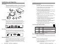
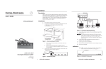
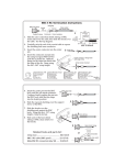
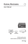
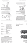
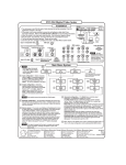
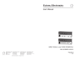
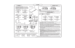
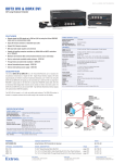
User’s Guide
P/2 DA2 MT
Distribution Amplifier
68-435-01 B
Printed in the USA
01 02
Installation and Operation
Easy Setup Procedure
Description
These easy-to-follow steps describe the general setup of the
P/2 DA2 MT. Refer to the previous application diagram.
The P/2 DA2 MT Distribution Amplifier can be mounted using the
included mounting brackets and screws. Audio input and output
connectors and an external DC power supply are also features of
the P/2 DA2 MT. See example application diagram below.
1. If the P/2 DA2 MT is to be mounted using the mounting
brackets, please refer to the previous section.
2. Power off the computer and its local monitor.
3. Connect the computer’s VGA output to the 15-pin female VGA
input on the front panel of the P/2 DA2 MT.
4. If a local monitor is being used, connect the monitor to the 15pin local monitor output on the front panel.
Stereo
Output
BUF
FER
ED
LOC
AL
COM
MON
ITO
PUT
ER
R
ID
INP
BU
PC Audio
Input
UT
PIN
4
ID
PIN1
1
P/2
P/2 DA2 MT
LO
CA
FF
ER
L MO
CO
MP
OR
UT
ER
ID
INP
UT
PIN
4
ID
PIN
11
P/2
5. Set termination pins (see Front Panel DIP Switch Settings
below).
Mounted under a Desk
or
Mounted in a Table
ED
NIT
DA
2 MT
DA
2
MT
6. If audio is being input, connect the audio source to the 3.5 mm
audio input jack on the front panel. Refer to the audio
connector diagrams on the last page.
LO
With
Mounting
Brackets
CA
L
MO
NIT
BU
OR
FFE
RE
D
INP
UT
CO
MP
UT
ER
ID
4
2
PIN
P/
11
M
PIN
2
ID
DA
T
7. Connect the output display device, such as a projector, VGAcompatible monitor, etc., to the 15-pin VGA data display
connector on the rear panel of the P/2 DA2 MT.
or
PC Computer
Projector
Video Monitor
Front Panel
8. Connect an audio device to the 3.5 mm captive screw audio
output connector on the rear panel. Refer to the audio
connector diagram on the following page.
The front panel consists of a 2-color LED indicator (amber
indicates power On only, green indicates power On with video
signal present), a 3.5 mm female audio input jack, a 15-pin
female VGA input, a 15-pin female VGA buffered local monitor
output, and 2 DIP switches that set the input termination.
COMPUTER
BUFFERED
INPUT
L O C A L M O N I TO R
9. Connect the 9-volt power plug of the included power supply
into the power input jack on the rear panel.
ID PIN 4
ID PIN11
Front Panel DIP Switch Settings
ID PIN 4
ID PIN11
Set the two DIP switch pin positions (on/up or off/down):
P/2 DA2 MT
Pin 4
off
Pin 11
off
Rear Panel
The rear panel consists of a 9-volt power input jack, a Level/
Peaking DIP switch to control video level and peaking (data
display device only), a 15-pin VGA output connector, and a 3.5
mm captive screw audio output connector.
POWER
9V DC
S PA R E
LEVEL/PEAKING
on
on
on
off
Function
computer input pins 4 & 11 passed to
local monitor output connector
provide ID bit termination when no
local monitor connected
provide correct MAC 13” ID bit
termination
DATA DISPLAY
Rear Panel DIP Switch Settings
Set the Level/Peaking DIP switch On (up) to increase level and
peaking of the data display, otherwise, set the switch Off (down).
0.5A MAX.
Mounting Bracket
The included mounting brackets are attached to the P/2 DA2 MT
using the 6 bracket screws, as shown on page 5. The unit may
then be mounted under a desk or some other suitable location
using the 4 wood screws (see mounting template). Optional
brackets are also available for vertical mounting (see mounting
template).
2
P/2 DA2 MT • Installation and Operation
Operation
1. Power on the computer and monitor.
2. Power on the output display device.
3. Power on the P/2 DA2 MT. The LED will light amber when the
power is on and will light green when the power is on and
there is an input present.
P/2 DA2 MT • Installation and Operation
3
Installation and Operation, cont’d
Audio Connections
Under Desk
P / 2 DA
2 MT
ID PIN
11
ID PIN
4
TER
I NIPNUPTU T
COMPU
M O N I TO
R
COMPU
NPUT
I N PI U T
TER
4
ID PIN
11
ID PIN
2 MT
P / 2 DA
P/2 DA2 MT • Installation and Operation
Thru Desk
All dimensions are in inches
Thru desk mounting template
R
D
LOCAL
P/2 DA2 MT • Installation and Operation
BUFFERE
4
(Requires mounting kit P/N 70-077-02)
or plugging the audio connectors incorrectly may
damage the audio output circuits.
M O N I TO
___ No sleeve means NO CONNECTION. Wiring errors
LOCAL
Balanced output: (high
impedance or 600 ohms)
BUFFERED
(high impedance)
= Bracket hole diameter - 4 places
Warning! Unbalanced output:
Recommended pilot drill hole size
for supplied screws = 3/32” x 1/4” deep.
p
5
Installation and Operation, cont’d
Specifications
Video
Gain ................................................ (0.7V) unity, (0.8V) 15%
Bandwidth ..................................... 300 MHz (-3dB)
Video input
Number/signal type ................... 1 VGA-UXGA RGBHV, RGBS, RGsB,
RsGsBs
Connectors ................................... 1 15-pin HD female
Minimum/maximum level(s) .... Analog ....... 0.4V to 1.4V p-p with no
offset at unity gain
Impedance .................................... 75 ohms
Horizontal frequency .................. 15 kHz to 135 kHz
Vertical frequency ....................... 30 Hz to 170 Hz
Return loss .................................... -38.3dB @ 5 MHz
Maximum DC offset .................... 200mV
Video output
Number/signal type ................... 2 VGA-UXGA RGBHV, RGBS, RGsB,
RsGsBs
(1 for display, 1 for local monitor output)
Connectors ................................... 2 15-pin HD female
Minimum/maximum levels ....... 0.4V to 1.4V p-p
Impedance .................................... 75 ohms
Return loss .................................... -41dB @ 5 MHz
DC offset ....................................... ±5 mV maximum with input at 0 offset
Sync
Recommended pilot drill hole size
for supplied screws = 3/32” x 1/4” deep.
Input type .....................................
Output type ..................................
Input level .....................................
Output level ..................................
Input impedance ..........................
Output impedance .......................
Max. propagation delay ..............
Max. rise/fall time .......................
Polarity ..........................................
RGBHV, RGBS, RGsB, RsGsBs
RGBHV, RGBS, RGsB, RsGsBs
3V to 5V p-p
TTL ............. 5V p-p
75 ohms or 510 ohms (selectable)
75 ohms
18.8 nS
4 nS
Positive or negative
Audio
Gain ................................................ Unbalanced 0dB, balanced +6dB
Frequency response .................... 20 Hz to 20 kHz, ±0.05dB
THD + Noise ................................. 0.03% @ 1 kHz at rated maximum output
drive
S/N ................................................ >90dB, balanced, at rated maximum
output drive (21dB)
Stereo channel separation .......... >80dB @ 1 kHz
6
P/2 DA2 MT • Installation and Operation
P/2 DA2 MT • Installation and Operation
7
CMRR ............................................ >75dB @ 20 Hz to 20 kHz
Audio input
Number/signal type ................... 1 stereo, unbalanced
Connectors ................................... 1 3.5 mm female stereo jack, 2-channel; tip
(L), ring (R), sleeve (GND)
Impedance .................................... >5 kohms unbalanced, DC coupled
Maximum level ............................ +8.5dBu (unbalanced
Audio output
Number/signal type ...................
Connectors ...................................
Impedance ....................................
Maximum level (Hi-Z) ................
1 stereo, balanced/unbalanced
1 3.5 mm captive screw connector, 5 pole
50 ohms unbalanced, 100 ohms balanced
>+14dBu, balanced or unbalanced at stated
%THD+N
Maximum level (600 ohm) ......... >+0dBu, balanced or unbalanced at stated
%THD+N
0dBu = 0.775 volts (RMS).
General
Power ............................................ 100VAC to 240VAC , 50/60 Hz, 5 watts,
external, autoswitchable; to 9VDC, 1A
power supply.
Temperature/humidity .............. Storage -40° to +158°F (-40° to +70°C) /
10% to 90%, non-condensing
Operating +32° to +122°F (0° to +50°C) /
10% to 90%, non-condensing
Rack mount .................................. No
Enclosure type .............................. Metal
Enclosure dimensions ................. 1.0" H x 5.7" W x 4.5" D
2.5 cm H x 14.5 cm W x 11.4 cm D
Product weight ............................. 0.6 lbs (0.3 kg)
Shipping weight ........................... 3 lbs (1.4 kg)
Vibration ....................................... ISTA/NSTA 1A in carton (International
Safe Transit Association)
Listings .......................................... UL, CUL
Compliances ................................. CE
MTBF ............................................. 30,000 hours
Warranty ....................................... 3 years parts and labor
Specifications are subject to change without notice.
www.extron.com
Extron Electronics, USA
Extron Electronics, Europe
Extron Electronics, Asia
Extron Electronics, Japan
1230 South Lewis Street
Anaheim, CA 92805
USA
714.491.1500
Fax 714.491.1517
Beeldschermweg 6C
3821 AH Amersfoort
The Netherlands
+31.33.453.4040
Fax +31.33.453.4050
135 Joo Seng Road, #04-01
PM Industrial Building
Singapore 368363
+65.6383.4400
Fax +65.6383.4664
Daisan DMJ Building 6F
3-9-1 Kudan Minami
Chiyoda-ku, Tokyo 102-0074 Japan
+81.3.3511.7655
Fax +81.3.3511.7656
© 2002 Extron Electronics. All rights reserved.