1
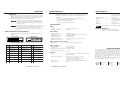
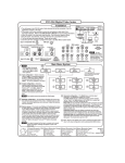
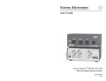
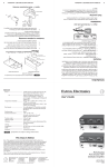
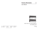
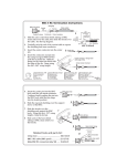
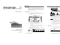
Installation
Description
D/2 DA4 DVI
The D/2 DA4 DVI Direct Digital Distribution Amplifier (DA) accepts a
Digital Visual Interface (DVI) signal or a Digital Flat Panel (DFP) signal
(with a DFP-to-DVI adapter) from a computer or other device that
outputs digital video. The D/2 DA4 DVI outputs four independently
buffered signals. The D/2 DA4 DVI is rack mountable and has an
internal switching power supply.
User’s Guide
D/2 DA 4 DVI
DIRECT DIGITAL DISTRIBUTION AMPLIFIER
100-240V
0.3A
OUTPUTS
1
LOCAL MONITOR
2
3
4
50/60 Hz
DVI cable
Installation
PRELIMINARY
Direct digital
displays
1.
Power off the computer and its local monitor.
2.
For optional rack mounting, mount the D/2 DA4 DVI on the left
or right side of a 19" 1U Universal Rack Shelf (Extron
part #60-190-01) (figure 1).
PC computer
digital video out
LCD projector
LCD projector
Monitor
Figure 3 — D/2 DA4 DVI typical application
D/2 DA4 DVI
DIRECT DIGITAL
DISTRIBU
TION AMPLIFIE
R
4.
The maximum permissible length of the DVI input and output
cables is 16.4 feet (5 meters). Ensure that the cables do not exceed
the maximum permissible length, otherwise images may be
distorted or missing. Extron does not guarantee signal integrity
beyond 16.4 feet.
4-40 X 1/8 screws
Use 2 mounting holes
on opposite corners
False front panel
Uses 2 front holes only
Figure 1 — Rack mounting the D/2 DA4
3.
Connect the computer monitor to the Local Monitor output of the
D/2 DA4 DVI.
a.
If feet were previously installed on the bottom of the case,
remove them.
b.
Mount the D/2 DA4 DVI on the rack shelf, using two
4-40 x 1/8 screws in opposite (diagonal) corners to secure the
case to the shelf.
Connect the D/2 DA4 DVI input cable (figure 2) to the DVI video
output port the of the computer (figure 3).
5.
Connect desired DVI-compatible LCD panels, monitors, or
projectors to the other output(s).
6.
Connect power to the D/2 DA4 DVI.
7.
Power on the local monitor and other connected display device(s).
8.
Power on the computer
Indicators
Power LED — Located on the front panel (figure 4), this lights to
indicate that the D/2 DA4 DVI is receiving power.
Power LED
DVI input cable
D/2 DA4 DVI
100-240V
0.3A
OUTPUTS
1
LOCAL MONITOR
Direct Digital Distribution Amplifier
2
3
D/2 DA4 DVI
4
DIRECT DIGITAL DISTRIBUTION AMPLIFIER
50/60 Hz
Figure 2 — D/2 DA4 rear panel
68-538-01 AX3
Printed in the USA
09 01
1
D/2 DA4 DVI • Installation
Figure 4 — D/2 DA4 DVI front panel
D/2 DA4 DVI • Installation and Operation
2
Operation
Troubleshooting
DVI/DFP signals run at a very high frequency and are especially
susceptible to bad video connections, too many adapters, or too long
cables. To avoid the loss of an image or image jitter, follow these
guidelines:
Operation
After the D/2 DA4 DVI and its connected devices are powered up, the
system is fully operational. If any problems are encountered, verify that
the cables are routed and connected properly, and that all display
devices have identical resolutions and refresh rates.
•
•
•
•
The direct digital video output is tailored for a specific monitor
resolution and refresh rate. Ensure that all display devices have
identical resolutions and refresh rates, otherwise images may be
distorted or missing.
Specifications are subject to change without notice.
Video
Bit rate ........................................... 1.6 gigabits/second/color
Pixel data bit depth ..................... 24 bits
Optional Adapters
• 26-497-01
• 26-498-01
Video input
DFP Connector Pin Assignments
Number/signal type ...................
Connectors ....................................
Horizontal frequency ..................
Vertical frequency .......................
Maximum resolutions .................
Minimum input voltage .............
Figure 5 and the table below define the pin assignments for the DVI
protocol.
1
9
17
Do not exceed 16.4 feet (5 meters) on the output of the DA.
Use only cable designed for DVI signals.
Limit or avoid the use of adapters.
Use only approved DVI/DFP connectors.
Enclosure dimensions ................. 1.75" H x 8.7" W x 9.5" D
4.5 cm H x 22.2 cm W x 24.1 cm D
(depth excludes connectors)
Shipping weight ........................... 6 lbs (2.7 kg)
Vibration ....................................... ISTA/NSTA 1A in carton (International Safe
Transit Association)
Approvals ..................................... UL, CUL, CE, FCC Class A
MTBF ............................................. 30,000 hours
Warranty ....................................... 2 years parts and labor
Specifications
Ensure that the computer and primary monitor are connected to
the D/2 DA4 DVI, and the D/2 DA4 DVI and monitor have power
applied, before applying power to the computer. If the other
devices are not turned on before the computer is, the image will
not appear.
Female connector
Specifications
Male connector
8
16
24
DVI (male), DFP (female)
DVI (female), DFP (male)
1 single link DVI-D
1 attached cable with DVI-D male connector
15 kHz to 135 kHz
30 Hz to 170 Hz
1280 x 1024 @ 85 Hz, 1600 x 1200 @ 60 Hz
0.15V p-p
Video signal characteristics
Figure 5 — DVI connectors
Rise/fall time ............................... 220 pS nominal, maximum 350 pS
Video output
Pin
Signal
Pin
Signal
Pin
Signal
1
TMDS Data 2-
9
TMDS Data 1-
17
TMDS Data 0-
2
TMDS Data 2+
10
TMDS Data 1+
18
TMDS Data 0+
3
TMDS Data 2/4
Shield
11
TMDS Data 1/3
Shield
19
TMDS Data 0/5
Shield
4
TMDS Data 4-
12
TMDS Data 3-
20
TMDS Data 5-
5
TMDS Data 4+
13
TMDS Data 3+
21
TMDS Data 5+
6
DDC Clock
14
+5 V Power
22
TMDS Clock Shield
7
DDC Data
15
Ground (+5 V)
23
TMDS Clock+
8
No Connection
16
Hot Plug Detect
24
TMDS Clock-
Number/signal type ...................
Connectors ....................................
Maximum output cable length ..
Minimum output voltage ...........
4 single link DVI-D
4 DVI-D female
16.4 feet (5 meters)
0.6V p-p
General
Power ............................................. 100VAC to 240VAC, 50/60 Hz, 13 watts, internal,
auto-switchable;
Temperature/humidity .............. Storage -40° to +158°F (-40° to +70°C) /
10% to 90%, non-condensing
Operating +32° to +122°F (0° to +50°C) /
10% to 90%, non-condensing
Rack mount ................................... Yes, with optional rack shelf, part #60-190-01
Enclosure type .............................. Metal
FCC Class A Notice
Note: This equipment has been tested and found to comply with the limits for a
Class A digital device, pursuant to part 15 of the FCC Rules. These limits are designed to
provide reasonable protection against harmful interference when the equipment is operated in
a commercial environment. This equipment generates, uses and can radiate radio frequency
energy and, if not installed and used in accordance with the instruction manual, may cause
harmful interference to radio communications. Operation of this equipment in a residential
area is likely to cause harmful interference, in which case the user will be required to correct
the interference at his own expense.
Note: This unit was tested with shielded cables on the peripheral devices. Shielded cables
must be used with the unit to ensure compliance.
www.extron.com
D/2 DA4 DVI • Operation
3
4
D/2 DA4 DVI • Specifications
Extron Electronics, USA
Extron Electronics, Europe
Extron Electronics, Asia
Extron Electronics, Japan
1230 South Lewis Street
Anaheim, CA 92805
USA
714.491.1500
Fax 714.491.1517
Beeldschermweg 6C
3821 AH Amersfoort
The Netherlands
+31.33.453.4040
Fax +31.33.453.4050
135 Joo Seng Road, #04-01
PM Industrial Building
Singapore 368363
+65.383.4400
Fax +65.383.4664
Daisan DMJ Building 6F
3-9-1 Kudan Minami
Chiyoda-ku, Tokyo 102-0074 Japan
+81.3.3511.7655
Fax +81.3.3511.7656
© 2001 Extron Electronics. All rights reserved.