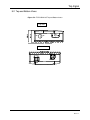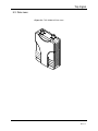
1
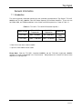
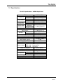
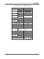
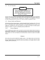
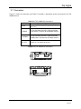
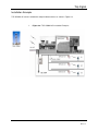
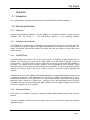
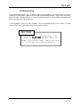
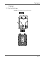
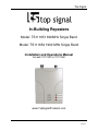
Top Signal
In-Building Repeaters
Model: TS111651 800MHz Single Band
Model: TS111652 1900 MHz Single Band
Installation and Operations Manual
For both TS111651 & TS111652
www.TopSignalProducts.com
Page 1
Top Signal
Table of Contents
1. General Information
1.1 Introduction
1.2 Specifications
1.3 Description
2 Installation
2.1 Introduction
2.2 Unpacking and Inspection
2.3 Preparation for Use
2.4 Before Installation
2.5 Antenna Installation
2.6 Bi-directional amplifier Installation
2.7 Connectors
2.8 Installation Example
3 Operation
3.1 Introduction
3.2 Operating Instructions
4 Trouble Shooting
5 Drawings
Page 2
Top Signal
General Information
1.1 Introduction
This manual provides information pertaining to the installation and operation of Top Signals’ TS111651
800MHz and TS11652 1900MHz “Ultra Slim Home Repeater” Bi-Directional Amplifiers. These units are
for CDMA, GSM, and TDMA modulations in the Cellular and PCS frequencies as shown in Table 1-1.
<Table 1-1: TS111651 / TS111652 Bi-Directional Amplifier >
Model Number
Down Link*
Frequencies
Up Link**
Frequencies
TS111651
869 ~ 894 MHz
824 ~ 849 MHz
TS111652
1930 ~ 1990 MHz
1850 ~ 1910 MHz
Modulation
CDMA,GSM
,TDMA
CDMA,GSM
, TDMA
*: Down Link is from base station to mobile
**: Up Link is from mobile to base station
Please Note: Both the TS111651 single-band 800MHz and the TS111662 single-band 1900MHz
amplifiers are setup and operated in the same manner. Going forward, this manual will refer to these
amplifiers as “Top Signal 65”.
Page 3
Top Signal
1.2 Specifications
TS111651 Specifications – 800MHz Single Band
ITEM
Frequency
Input Power
Linear Gain
(Center Freq.)
Output Power
(Center Freq.)
Down Link
Up Link
Down Link
Up Link
Down Link
Up Link
Down Link
Up Link
SPECIFICATION
869 ~ 894 MHz
824 ~ 849 MHz
- 28 dBm max/Total
- 28 dBm max/Total
65 dB ( ±1 dB )
65 dB ( ±1 dB )
+ 12 dBm/CDMA1FA
Up / Down link ALC Range
> 25 dB
Gain Flatness
< 5 dB max (p – p)
Fc ± 750 KHz
-45 dBc ( RBW =30 KHz )
Spurious
Fc ± 1.98 MHz -50 dBc ( RBW =30 KHz )
1 dB Compression
+ 22 dBm
rd
3 Order Intercept
+ 31 dBm
Down / Up Shutdown Level
+14 dBm ( ±1 dB)
Noise Figure, Typical
< 5 dB
Propagation Delay
< 1 µs max
VSWR, Typical
< 1.6 : 1
GREEN ON : Power Normal
Alarm & Status RED 1 ON : Down link Fail
RED 2 ON : Up link Fail
Power Consumption
5.3 V / 750 mA
Input Voltage (Adapter)
RF Connectors
Operating
Temperature
Storage
Dimensions( W x H x D , inch)
Weight
FCC Type Acceptance
DC 5.3 V / 1.8 A
N-Type Connector
-10 °C to 40 °C
-30 °C to 80 °C
5.8” x 4.6” x 1.9”
1.4 Kg ( 3.1 lb )
Q4EUHSR-800H
Page 4
Top Signal
TS111652 Specifications – 1900MHz Single Band
ITEM
Frequency
Input Power
Linear Gain
(Center Freq.)
Output Power
(Center Freq.)
Down Link
Up Link
Down Link
Up Link
Down Link
Up Link
Down Link
Up Link
SPECIFICATION
1930 ~ 1990 MHz
1850 ~ 1910 MHz
- 28 dBm max/Total
- 28 dBm max/Total
65 dB ( ±1 dB )
65 dB ( ±1 dB )
+ 12 dBm/CDMA1FA
Up / Down link ALC Range
> 25 dB
Gain Flatness
< 5 dB max (p – p)
Fc ± 885 KHz
-45 dBc
Spurious
Fc ± 1.98 MHz
-50 dBc
1 dB Compression
+ 22 dBm
rd
3 Order Intercept
+ 31 dBm
Down / Up Shutdown Level
+14 dBm ( ±1 dB)
Noise Figure, Typical
< 5 dB
Propagation Delay
< 1 µs max
VSWR, Typical
< 1.6 : 1
GREEN ON : Power Normal
Alarm & Status RED 1 ON : Down link Fail
RED 2 ON : Up link Fail
Power Consumption
5.3 V / 900 mA
Input Voltage (Adapter)
RF Connectors
Operating
Temperature
Storage
Dimensions( W x H x D , inch)
Weight
CE Mark
DC 5.3 V / 1.8 A
N-Type Connector
-10 °C to 40 °C
-30 °C to 80 °C
5.8” x 4.6” x 1.9”
1.4 Kg ( 3.1 lb )
Page 5
Top Signal
1.3 Description
This product is designed for small offices, home offices, garages and parking lots, helping to improve
signal strength and wireless network coverage inside.
Outdoor antenna receives signal from base stations, then the TOP SIGNAL 65 Bi-Directional Amplifier
amplifies the signal. Boosted signal is passed through to the indoor antenna(s). Conversely, signals from
handsets are amplified, and then transmitted to the base stations.
Installation
2.1 Introduction
This section provides information for the installation and setup of the TOP SIGNAL 65 Bi-Directional
Amplifier. The information consists of procedures for unpacking, inspection and preparation for the
installation, as well as the actual installation and the setup.
2.2 Unpacking and Inspection
Examine the shipping carton for damage before unpacking the unit. If the shipping carton is damaged, try
to have the carrier’s agent present when the equipment is unpacked. If visual inspection reveals physical
damage(s) to the equipment, you should send it back for replacement.
Verify that the equipment is complete, as listed on the packing slip. Contact the seller if any component is
missing.
2.3 Preparation for Use
2.3.1
Power Requirements
The power supply of the TOP SIGNAL 65 accepts 5.4 VDC. Power consumption of the TOP SIGNAL 65
is approximately 4.0 Watts.
2.3.2
Operating Environment
The TOP SIGNAL 65 is intended for indoor use only. Do not install it where it might be exposed to the
outside elements as this could result in destruction of the unit and other hazards.
For normal operations, the environmental conditions should be as follow:
Temperature range: –10 °C to 40 °C
Maximum Humidity: 95 %
Page 6
Top Signal
2.4 Before Installation
You will need to determine the following before beginning the TOP SIGNAL 65 installation:
a. Location where the outdoor antenna is to be installed
b. Location where the indoor antenna is to be installed
c.
Location where the TOP SIGNAL 65 is to be installed
d. Length and type of coaxial cable needed to connect from the outdoor antenna to the bi-directional
amplifier
e. Length and type of coaxial cable needed to connect from the bi-directional amplifier unit to the indoor
antenna
2.5 Antenna Installation
2.5.1
Outdoor Antenna
Select a site for your outdoor antenna, making sure that you have enough signal strength at that location.
Connect the antenna to the bi-directional amplifier using an RF coaxial cable.
Please refer to the instructions provided by the manufacturer for antenna installation.
If you are using a directional antenna such as a Yagi type, a Patch type, you may want to install the
antenna temporarily first. You can come back and optimize once you have installed and powered up the
bi-directional amplifier.
2.5.2
Indoor Antenna
Install the indoor antenna at a convenient location. It should be free of metallic obstructions in order to
have an effective coverage. Depending on the circumstance of the installation, either one or a
combination of following antennas can be used:
Ceiling mount antenna, Wall mount patch antenna omni-directional antenna and Corner reflector antenna.
2.6 Bi-directional amplifier Installation
TOP SIGNAL 65 is an indoor bi-directional amplifier. Accordingly, the environment of the intended
installation site needs to be considered. The bi-directional amplifier must be shielded from moisture, such
as rain, and excessive temperatures. The operating temperatures should be between -10 °C and 40
°C.
Page 7
Top Signal
2.6.1
Turn-On Procedure
Caution!
Please make sure all RF connectors are
tightened and cables and antennas are
connected. Powering up the unit with no
antenna attached might cause irreparable
damage to the amplifier.
Once you verify that the antennas are attached correctly, Connect AC/DC Adaptor on the bi-directional
amplifier’s DC IN connector. Then switch the ON / OFF switch to ON position. The Power indicator LED
should be green. Verify that none of the “ALARM” LEDs is illuminated. If an ALARM LED is lit, consult
the trouble shooting pages of this manual, or “2.6.2 Antenna Isolation and Alignment” section.
2.6.2
Antenna Isolation and Alignment
Good isolation between the two antennas is critical for the operation of the repeater system. This is not
an issue as long as the distance between the outside antennas and the inside antenna is at least 15 ft,
there is a wall between them, and the outside antenna is not pointed toward the inside antenna. TOP
SIGNAL 65 is equipped with an over drive protection circuit, which will also detect the isolation problem
between the antennas. This alarm is indicated by a blinking “ALARM” LED.
2.6.2.1
Antenna Alignment
If you are triggering the overdrive alarms at any point, try to increase the isolation between the antennas
by relocating the indoor antenna. The indoor antenna should be placed physically as far away from the
outdoor antenna as practical. If you are using directional antennas, try to find a location for the indoor
antenna where it can cover the needed area and oriented back to back with respect to the outdoor
antenna.
<Optional>
At this point, you may want to optimize the outdoor antenna. If the outdoor antenna can be turned in
place, try turning it from one end to the other by one inch increment. At each point, observe the signal
strength in indoor coverage area. When you find the best direction for the outdoor antenna, tie down
everything and secure the antenna.
Page 8
Top Signal
2.7 Connectors
Figure 2-7 shows the connectors and Table 2-7 provides a description of each connector on the TOP
SIGNAL 65 unit
<Table 2-7: TOP SIGNAL 65 Connectors>
Label
Description
Connect AC/DC Adaptor for supplying DC power
to the unit
DC IN
TO BASE
N-Type connector transmits signal to and from
base stations. Connects to the outdoor antenna.
TO MOBILE
N-Type connector transmits signal to and from
mobile phones. Connects to the indoor antenna.
ON / OFF
Power On / Off switch for the unit.
<Figure 2-7:TOP SIGNAL 65 Connectors>
ON
OFF
DC IN
TO BASE
TO MOBILE
Page 9
Top Signal
Installation Example
TOP SIGNAL 65 can be installed with multiple indoor antennas as shown in Figure 2-8.
1.
<Figure 2-8: TOP SIGNAL 65 Installation Example>
Page 10
Top Signal
Operation
3.1 Introduction
This section provides information for operating the TOP SIGNAL 65 Bi-Directional Amplifier.
3.2 Operating Instruction
3.2.1
Power-up
Connect the Bi-Directional Amplifier to AC/DC Adaptor. If no ALARM condition is present, only the
“POWER” LED will remain lit.
The Bi-Directional Amplifier is then operating properly.
3.2.2
Automatic Level Control
TOP SIGNAL 65 is equipped with an Automatic Level Control (ALC) both on the up-link and down-link.
ALC automatically adjusts the gain of the amplifier depending on the strength of the input signal. This
feature, for example, helps prevent amplifier shut down when you are making a call near the service
(indoor) antenna.
3.2.3
ALARM Status
There are overdrive fail alarms on the unit, one for the up link, “Tx ALARM”, the other for down link “Rx
ALARM”. Over driving occurs when the RF output power of the Bi-Directional Amplifier exceeds a
prescribed limit. This means that the input RF power level is too high, or the Bi-Directional Amplifier is
oscillating. The condition may be transient, caused by a passing emergency vehicle emitting a strong
signal for example, or permanent, due to the proximity to a base station. It may also indicate low isolation
between the antennas, (please refer to the section 2.6.2 of this manual for antenna alignment and
isolation.)
The overdrive fail on the TOP SIGNAL 65 Bi-Directional Amplifier is design to detect whether the over driving
is transient or permanent. If the output power level of Up Link exceeds a prescribed limit, Up link is
disconnected and the FAIL LED (RED) turns on. Bi-Directional Amplifier automatically checks output
power level every 1 minute of a 5 minute cycle. During this cycle, if the output power returns to normal,
the amplifier will revert to its normal operation mode. However, if the over-power condition persists after 5
minutes, the amplifier will shut it self down.
3.2.4
Corrective Actions
In the event of a shut down, re-aligning or moving the indoor and/or outdoor antennas may solve the
problem.
To reset the amplifier, disconnect the power supply, wait for at least 20 seconds, and plug in the power
supply back again.
Page 11
Top Signal
Troubleshooting
If the bi-directional amplifier does not operate properly after installation, first check that the installation
procedures as described in section 2 of this manual were followed correctly. Inspect each connection,
both RF and AC, and connectors for a secure fit, checking to see if all the connections are made to the
proper ports of the unit and the antennas.
If the malfunction is due to an alarm condition, refer to the appropriate part of the section 3.2 of this
manual. Corrective actions may be taken for the overdrive alarms.
CAUTION!
There are no user serviceable parts in Top
Signal 65. DO NOT OPEN the unit. There is a
danger of an electric shock. Opening the covers
of the unit will void all warranties.
Page 12
Top Signal
Drawings
5.1 Front and Back views
<Figure 55-1: TOP SIGNAL 65 Front and Back views>
Front View
POWER
TX FAIL
RX FAIL
Page 13
Top Signal
5.2 Top and Bottom Views
<Figure 5-2: TOP SIGNAL 65 Top and Bottom views>
Top View
ON
OFF
DC IN
Bottom View
TO BASE
TO MOBILE
Page 14
Top Signal
5.3 Side views
<Figure 5-3: TOP SIGNAL 65 Side view>
Page 15