1
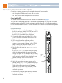
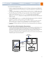
PROMENTUM™ QUAD AMC CARRIER INSTALLATION GUIDE ATCA-1200 Follow ESD precautions During installation, follow proper electrostatic discharge procedures when handling the carrier and electrical equipment. WARNING! This product contains static-sensitive components and should be handled with care. Failure to employ adequate antistatic measures can cause irreparable damage to components. Handle this product only when wearing a grounded wrist strap at a grounded work area. Additional precautions and ESD information are provided at www.radisys.com/esd. Do not remove the carrier from its ESD shielding bag until a step instructs you to do so. Failure to follow ESD precautions may cause hardware damage. Prepare for installation Installation of the carrier requires the following: An AdvancedTCA® (ATCA®) shelf, such as a RadiSys ATCA-6000 or ATCA-6006 shelf Adequate ventilation for the shelf To access the carrier through an external computer, you may need the following: An optional rear transition module (RTM) designed for the carrier A 9-pin D-shell to RJ-45 serial port cable A standard crossover Ethernet cable Install AMCs AMCs are typically pre-installed in the carrier at the factory. This document describes how to install and to set up the Promentum™ ATCA-1200 Quad Advanced Mezzanine Card (AMC) carrier. Note: If you are installing your own AMCs, verify they are compatible with the carrier and listed with UL. Check the specified requirements for form factor, power, cooling, and connectors in the ATCA-1200 Quad AMC Carrier Reference and in the documentation that came with the AMCs. Follow ESD precautions when installing AMCs on the carrier (see information above). 007-02570-0000 • September 2007 Copyright © 2007 by RadiSys Corporation. All rights reserved. RadiSys is a registered trademark and Promentum is a trademark of RadiSys Corporation. Linux is a registered trademark of Linus Torvalds. AdvancedTCA and ATCA are registered trademarks of PCI Industrial Computer Manufacturers Group. Procomm Plus and Symantec are registered trademarks of Symantec Corporation. All other trademarks, registered trademarks, service marks, and trade names are the property of their respective owners. Installation Guide Install the RTM (optional) An RTM designed for the carrier can be used for I/O access. The RTM can be installed at any time, but it is easier to do so before installing the carrier in the shelf. This section describes the RTM being installed before the carrier. Preparation Before installing the RTM: Verify it is compatible with the carrier. Follow ESD precautions. See page 1 for more information. Determine which front node slot in the shelf you plan to use for the carrier. The RTM will be installed in the corresponding rear slot. For example, if you intend to install the carrier in front physical slot number 3, install the RTM in rear physical slot number 3. Remove the airflow management panel installed in the rear node slot. RTM for carrier Note: If you are using another vendor’s RTM, check the RTM’s documentation for installation instructions or precautions. Installation 1. Follow ESD precautions and make sure you are adequately grounded before handling the RTM. 2. Remove the RTM from its antistatic bag. 3. Open both ejector latches on the RTM. 4. Slide the RTM into the empty rear slot on the shelf. 5. Close both ejector latches. Push in the thumbscrews and tighten. 6. Install the carrier (see below). 7. After installing the carrier, verify the RTM’s power LED is green (the RTM gets its power through the front module). 8. Use the shelf management software to verify the RTM and the corresponding front module are available as resources and operating correctly. Install the carrier 1. This section assumes you are installing the carrier in an ATCA shelf and the shelf power is on. The ATCA shelf architecture lets you insert and remove the carrier from the shelf without powering down the system. 2. Follow ESD precautions and make sure you are adequately grounded before handling the carrier (see page 1). 2 Front panel LED indicators 3. Remove the carrier from its antistatic bag. 4. Open both ejector handles outward at the same time. 5. Slide the carrier into one of the node slots on the shelf. If correctly aligned, the edges of the carrier will fit within the narrow guide rails of the shelf and the carrier will mate with the alignment receptacles of the corresponding compatible RTM (if one is installed). 6. Once the carrier is inserted all the way into the shelf, simultaneously close both ejector latches inward. This will seat the carrier’s connectors into the shelf’s backplane. Open ejector handles Pull handle out The hot-swap (H/S) LED flashes until the carrier is fully powered (see Front panel LED indicators below). Once powered, the H/S LED will turn off and the Power LED will become green. If the H/S LED remains solid blue or keeps flashing after the carrier is inserted, it indicates the installation may have failed. Please see the ATCA-1200 Quad AMC Carrier Reference for information on troubleshooting LED states. Slide hot-swap latch toward handle and pull handle out 7. Secure the carrier in its slot by hand tightening the two fastening screws on each end of the carrier’s front panel. 8. If the optional RTM is installed, verify the RTM’s power LED is green. 9. Use the shelf management software to verify the carrier and the RTM are available as resources and are operating correctly. Front panel LED indicators Label LED Definition Color States OOS LED 1 Out of service Red or amber = Out of service Off = Normal operation PWR LED 2 Power Amber = Application defined Green = Power good APP LED 3 Application Amber = Application defined Green = Application defined H/S H/S Hot swap Long blink = Searching for Shelf Manager Solid blue = Ready for hot swap Short blink = Preparing for removal Off = Normal operation 3 Installation Guide Connect to an external computer and the network Connect to an external computer and the network using one of these methods: with the optional RTM designed to mate with the carrier with Telnet or SSH via the backplane Ethernet interfaces Connect with the RTM This section assumes you have installed the optional RTM as described on page 2. The Quad AMC carrier can be accessed by an external computer through the serial and the Ethernet maintenance ports on the RTM. Use the serial port to perform diagnostic and verification procedures. Use the Ethernet maintenance port to connect the carrier to the network and to perform configuration procedures. Connect to the serial port 1. Connect the serial port cable by plugging one end into the RJ-45 serial port (labeled “LMP SER”) on the RTM. For a description of the serial port cable pinouts, see the ATCA-1200 Quad AMC Carrier Reference. RTM front panel 2. Connect the cable’s other end to the COM1 or the COM2 serial port of an external computer, such as a laptop. 3. Start a terminal-emulator application, such as Procomm Plus® or minicom, from the operating system on your computer or laptop. Specify 115200 baud, 8 data bits, no parity, one stop bit, and no hardware or software flow control. 4. Press the Enter key to get the ATCA-1200 login prompt. If the ATCA-1200 login prompt does not display, check the cabling and verify the terminal-emulator settings are correct. You can also check the LED states on the carrier. If necessary, press the reset button and see if any text is displayed. If text is displayed, it may provide some hints as to what else to check. 5. Enter admin at the prompt. 6. Verify that you receive a welcome message and a prompt showing ATCA-1200#. From this prompt you can perform diagnostic and verification procedures. To log off the carrier at any time, enter the exit command. See the ATCA-1200 Quad AMC Carrier Reference for information on diagnostic and verification procedures. 7. Disconnect the serial port cable from the RTM when you are through performing the diagnostic and verification procedures. 4 Ethernet maintenance port (LMP ETH) Serial port (LMP SER) Power LED Connect to an external computer and the network Connect to the Ethernet maintenance port 1. Connect a crossover Ethernet cable between the RJ-45 Ethernet maintenance port (labeled LMP ETH) on the RTM and the RJ-45 Ethernet port on a Linux host computer that is connected to your network. 2. Configure the host computer to a subnet IP address of 10.0.0.x. For the “x” variable, select a value from the range 2-254 (for example, 10.0.0.2 to 10.0.0.254). Set the netmask to 255.255.255.0. 3. From the host computer, use a Telnet or an SSH connection to access the carrier’s default IP address 10.0.0.1 (port 23). The ATCA-1200 login prompt for the carrier will display. If the ATCA-1200 login prompt does not display, verify the Telnet connection to the carrier’s IP address is correct. 4. Log in as admin to get the ATCA-1200# prompt. From this prompt you can perform configuration procedures. To log off the carrier at any time, enter the exit command. Note: To connect to the Linux shell on the carrier, use either a serial port or a Telnet connection. After connecting, log in as root and enter ifconfig to view eth0 configuration settings. 5. Disconnect the Ethernet cable from the RTM when you are through performing the configuration procedures. Connect with Telnet or SSH via the backplane Ethernet interfaces 1. Connect a crossover Ethernet cable between the RJ-45 Ethernet port on a module that has access to the Base Ethernet interface and the RJ-45 Ethernet port on a Linux host computer that is connected to your network. Examples of modules that have access to the Base Ethernet interface include CPU modules and switch and control modules (like the RadiSys ATCA-2210 SCM). For example, if the ATCA-2210 SCM is installed on the shelf, you can connect to the Base Ethernet SFP port (e.g. port 1/6) on the front panel. Front panel Base port (e.g., 1/6) Base Ethernet switch Ethernet switch Fabric Ethernet switch Base backplane link eth1 interface Local management processor Local management processor ATCA-1200 ATCA-2210 Quad AMC Carrier SCM 5 Installation Guide 2. Configure the IP address of the host computer using the following: 10.2.<chassis>.x. The <chassis> parameter represents the shelf address (the physical location of the shelf within a central office). For the “x” variable, select a value from the range 17-254 (for example, 10.2.<chassis>.17 to 10.2.<chassis>.254). Set the subnet to 255.255.0.0 for the eth1:0 interface. 3. From the host computer use a Telnet or an SSH connection to access the eth1:0 interface on the carrier. The static IP address is: 10.2.<chassis>.<slot>. The <chassis> parameter represents the shelf address and the <slot> parameter represents the carrier’s location in the shelf. The ATCA-1200# login prompt for the carrier will display. If the prompt does not display, verify the Telnet or the SSH connection to the static IP address is correct. 4. Log in as admin to get the ATCA-1200# prompt. From this prompt you can perform configuration procedures. To log off the carrier at any time, enter the exit command. Note: To connect to the Linux shell on the carrier, log in as root and enter ifconfig to view eth1 configuration settings. 5. Disconnect the Ethernet cable from the Base Ethernet port on the module through when you are done performing the configuration procedures. Verify Ethernet switch operation Use these steps to view port status and to enable ports on the Ethernet switch. View port status 1. Verify you are at this prompt. ATCA-1200# If you are not at the appropriate prompt, see Connect to an external computer and the network on page 4 for instructions on how to get there. 2. Enter this command to access the Ethernet command line interface. ethernet This results in the ATCA-1200-Eth# prompt. 3. Enter this command to show the status of the ports. show port all View the status information of the ports to see which ports are enabled. If needed, press the space bar to view more of the list. By default, Base port 0/1 is enabled. 4. Proceed to the applicable section or step: 6 To change which port is enabled, see Change the enabled port on page 7. To keep the default settings, continue with step 5. Verify Ethernet switch operation 5. Enter the exit command to return to the ATCA-1200# prompt. If you are asked to save changes, enter y for yes or n for no. If you choose y for yes, this configuration will be saved as the startup configuration. 6. Enter the exit command to log off the carrier. If you are connected to the carrier using the RTM, disconnect the cable from the serial port or the Ethernet maintenance port on the RTM. Change the enabled port Note: RadiSys recommends only having one port enabled at a time on the carrier if the platform configuration has two switches with interconnected switching domains. A connection between the Base Ethernet switching domains is enabled by default on RadiSys switches. 1. Verify you are at this prompt. ATCA-1200-Eth# If you are not at the appropriate prompt, see Connect to an external computer and the network on page 4 for instructions on how to get there. 2. Follow these steps to enable a specific port (other than the default port of 0/1): A. Enter this command. configure B. Enter the specific port (interface) number to enable. The s variable represents the specified slot or bay. The p variable represents an individual port within the group of ports for the specified slot or bay. interface <s/p> Where s and p have the following values. ATCA-6000 backplane slots ATCA-6006 backplane slots AMC ports Internal ports RTM s=0 s=0 s=1-4 s=5 s=6 p=1-4 p=1-4 p=1-5 p=1-2 p=1-2 C. Enter this series of commands to enable the port. a. no shutdown b. exit 3. Follow these steps to disable the default port of 0/1. A. Enter this command. configure B. Enter the port number to disable. For the default port, this number is 0/1. interface 0/1 C. Enter the next two commands to disable the specified port. a. shutdown b. exit 7 Installation Guide D. Enter the next two commands to return to the ATCA-1200# prompt. a. exit b. exit If you are asked to save changes, enter y for yes or n for no. If you choose y for yes, this configuration will be saved as the startup configuration. 4. Enter the exit command again, to log off the carrier. If you are connected to the carrier using the RTM, disconnect the cable from the serial port or the Ethernet maintenance port on the RTM. Where to go from here See the ATCA-1200 Quad AMC Carrier Reference for detailed information on the carrier’s electrical, mechanical, environmental, and software aspects. Additional software information is covered in the Ethernet Switching Software Reference. You should also set passwords for the root and the admin users and create user accounts for those who do not require administrative privileges. See the ATCA-1200 Quad AMC Carrier Reference for more information. Where to get more product information Please visit the RadiSys Web site at www.radisys.com for product information and other resources. Downloads (manuals, release notes, software, etc.) are available via the Technical Support Library product links at www.radisys.com/support or the product pages at www.radisys.com/products. 8


![VadaTech VT85x User Manual[1]](http://vs1.manualzilla.com/store/data/005803212_1-bb50408d9ec4263de47f5dcd2a97e7b3-150x150.png)