1
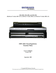
SERVICE MANUAL EPC®-2100/EPC-2101 PV5000HX2(-IDE) Series SBC P/N 007-01246-0000 © 2001 RadiSys Corporation All Rights Reserved Printed in USA June 2001 EPC-2100 and EPC-2101 Single-Board Computers Limited Warranty A. RadiSys Corporation warrants that the item sold by it hereunder will be free from defects in materials or workmanship, under normal use and service, for a period of 2 years from date of shipment. Said item will meet the specifications in effect at the time of manufacture. The sole obligation of RadiSys under this warranty shall be, at its option, to repair or replace, without charge, any defective component of said item, within a reasonable period of time. B. RadiSys Corporation shall not be liable under this warranty for (i) the item that the Buyer alleges to be defective and was repaired or altered by someone other than an authorized representative of RadiSys, unless such repair or alteration was effected pursuant to prior written approval of RadiSys, or (ii) where the Buyer fails to notify RadiSys of any alleged defect within the period of warranty, or (iii) where the Buyer fails to return the allegedly defective item to RadiSys Corporation, in Houston, Texas, USA, freight prepaid, or (iv) where the item was altered or damaged in a way which RadiSys reasonably determines to affect the performance and reliability of the item, or (v) where the item was subject to misuse, neglect, or accident. The rights and remedies granted to the Buyer under this paragraph constitute the Buyer's sole and exclusive remedy against RadiSys Corporation, its officers, agents, and employees, for negligence, inexcusable delay, breach of warranty, express or implied, or any other default relating to the item or the duties of RadiSys to eliminate any errors. This warranty supersedes any other warranty, whether expressed, implied, or statutory, including but not limited to any warranty for fitness of purpose, merchantability, or freedom from infringement or the like, and any warranty otherwise arising out of any proposal, specifications, or sample. Furthermore, RadiSys Corporation neither assumes nor authorizes any person to assume for it any other liability. The software included with this equipment is warranted only in accordance with the terms of its license agreement. Except as warranted in that license agreement, the manufacturer of the software disclaims all warranties and conditions with regard to the software, including all implied warranties and conditions of merchantability, fitness for a particular purpose, title, and non-infringement. Every effort has been made to ensure that the information provided in this manual is complete and accurate. However, technical inaccuracies or typographical errors may be inadvertently included. RadiSys assumes no responsibility for any errors that may be contained in this document. RadiSys makes no promise to update or keep current the information contained in this document. Information in this document, including product specifications, is subject to change without notice. All tradenames referenced are the service mark, trademark, or registered trademark of the respective manufacturer. ii Service Manual Important Always use caution when handling or operating the equipment. Only qualified and trained electronics service personnel should access the equipment. Use extreme caution when installing or removing components. For additional information, please contact RadiSys Technical Support at 800–627–8700 or 713–541–8200 Monday through Friday between 8:00 a.m. and 5:00 p.m., Central Time, continental USA. Wichtig Arbeiten am System bzw. Betrieb des Systems, sollten immer mit der nötigen Vorsicht vorgenommen werden. Nur qualifiziertes und ausgebildetes Fachpersonal sollte am Inneren des Gerätes arbeiten. Beim Installieren und Entfernen von Komponenten ist besondere Vorsicht geboten. Für weitere Informationen wenden Sie sich bitte an den Technical Support von RadiSys: • USA: 800–627–8700 oder 713–541–8200 Montags bis Freitags von 0800 Uhr bis 1700 Uhr, Central USA. • International: +31–36–5365595 Montags bis Freitags von 0830 Uhr bis 1700 Uhr. (CET GMT +1.00) Changes or modifications not expressly approved by RadiSys Corporation could void the product warranty and the user’s authority to operate the equipment. Service Manual iii EPC-2100 and EPC-2101 Single-Board Computers Notice This equipment has been tested and found to comply with the limits for a Class A digital device, pursuant to Part 15 of the FCC Rules. These limits are designed to provide reasonable protection against harmful interference when the equipment is operated in a commercial environment. This equipment generates, uses, and can emit radio frequency energy and, if not installed and used in accordance with this instruction manual, may cause harmful interference to radio communications. Operation of this equipment in a residential area is likely to cause harmful interference, in which case, the user will be required to correct the interference at the user’s expense. This device complies with Part 15 of the FCC Rules. Operation is subject to the following conditions: • This device may not cause harmful interference • This device must accept any interference received, including interference that may cause undesired operation Any change or modification not expressly approved by the manufacturer is prohibited and could void the user’s authority to operate the equipment. This product also meets requirements for compliance with EN55022, Class B ITE. iv Service Manual Symbols Notice: This symbol indicates an item for special consideration. Warning: This symbol indicates the presence of a potential hazard that can cause personal injury or equipment damage. Only qualified and trained electronics service personnel should access the equipment. Service Manual v EPC-2100 and EPC-2101 Single-Board Computers Customer Support Accessing the Web Site In-depth printable service manuals and other documentation are available for download from the RadiSys Web site: http://www.radisys.com Then click on Support to access a link to the documentation, drivers, and BIOS. Documentation is available at this Web site in Adobe® Acrobat® .PDF format, and may be viewed and printed using the free Acrobat® Reader™ software. BIOS files are available as selfextracting disk image files. Links are provided to various partners’ web sites where any files and tools needed to install drivers are available for download. Calling Technical Support 1. Have the RadiSys product model and serial number available. 2. Call Technical Support: In the continental USA, Monday – Friday, 8:00 a.m. – 5:00 p.m., Central Time, dial • 800–627–8700. Outside the USA, dial 713–541–8200 (add long distance/international access codes). • In Europe, Monday – Friday, 8:30 a.m. – 5:00 p.m., dial +31–36–5365595. • Inspection of Contents / Packaging of Product The packaging for this product has been tested to assure that it will withstand responsible handling by the carrier. Caution: Inspect contents immediately and file a claim with the delivering carrier for any damage. Save the shipping box and packaging material to use for any further shipment of this equipment. However, if the packaging is damaged and is not suitable for shipment, call RadiSys Technical Support to obtain new packaging. The warranty may be void if the product is returned using unapproved or damaged original packaging. Returning Your Product A Returned Material Authorization (RMA) number must be written on the outside of the shipping carton of all equipment returned to RadiSys for service and/or repair. It is recommended that any correspondence included with the carton contents also refer to the RMA number. Note: The factory will refuse the shipment if it is sent freight collect or if it does not display an RMA number. vi Service Manual Table of Contents Chapter 1 Introduction 1 EPC-2100/2101 (PV5000HX2(-M)) Series SBC ...................................................................2 Chapter 2 7 Steps to Operation 5 Handling the EPC-2100/2101.................................................................................................6 Step 1: Check Jumper Settings ...............................................................................................8 Step 2: Check Switch Settings..............................................................................................10 Step 3: Install the SBC .........................................................................................................12 Step 4: Attach Peripherals to Headers ..................................................................................14 Step 5: Attach Peripherals to Connectors .............................................................................16 Step 6: Power-On the System...............................................................................................18 Step 7: Run the Setup Utility................................................................................................19 Chapter 3 Technical Data 27 Specifications .......................................................................................................................28 Pin Signals ............................................................................................................................30 Display System .....................................................................................................................36 Installing Memory ................................................................................................................38 Service Manual vii EPC-2101 Single-Board Computer List of Figures Figure 1. Figure 2. Figure 3. Figure 4. Figure 5. Figure 6. Figure 7. Figure 8. Figure 9. Figure 10. Figure 11. Figure 12. viii Components and Layout..................................................................................... 3 Safely Handling the SBC ................................................................................... 7 Jumper Block Locations ..................................................................................... 9 Switch Block Location ..................................................................................... 11 Installing the SBC ............................................................................................ 13 Peripheral Header Locations ............................................................................ 15 Peripheral Connector Locations ....................................................................... 17 Setup Utility Main Menu.................................................................................. 20 Serial and Parallel Headers and Connectors..................................................... 31 Peripheral Headers and Connectors ................................................................. 33 Flat Panel Display Header ................................................................................ 35 Memory Sockets............................................................................................... 39 Service Manual List of Tables Table 1. Table 2. Table 3. Table 4. Table 5. Table 6. Table 7. Table 8. Table 9. Table 10. Table 11. Table 12. Table 13. Table 14. Table 15. Service Manual Jumper Block Settings ........................................................................................... 8 Jumper Block Functions ........................................................................................ 9 Switch Settings .................................................................................................... 10 Installing the SBC ................................................................................................ 12 Main Menu Options and Item Values.................................................................. 21 Advanced Menu Options and Item Values .......................................................... 22 Security Menu Options and Item Values............................................................. 24 Power Menu Options and Item Values ................................................................ 24 Server Menu Options and Item Values................................................................ 25 Environmental Tolerances ................................................................................... 28 System Specifications .......................................................................................... 29 Serial and Parallel Port Pin Signals ..................................................................... 30 Peripheral Header and Connector Pin Signals..................................................... 32 Flat Panel Display Header Pin Signals ................................................................ 34 Memory Combinations ........................................................................................ 39 ix EPC-2101 Single-Board Computer Notes x Service Manual 1 Introduction Chapter 1 This chapter discusses the primary features of the EPC-2100/EPC-2101 SingleBoard Computer (PV5000HX2 series). If you are familiar with the primary components and functions of the EPC-2100/EPC-2101, and you wish to quickly begin operating the SBC, go to Chapter 2, “7 Steps to Operation,” page 5. Then read this chapter later at your convenience. Service Manual 1 EPC-2100/EPC-2101 Single-Board Computer EPC-2100/2101 (PV5000HX2(-M)) Series SBC Overview The RadiSys EPC-2100/EPC-2101 Single Board Computers (SBC) provide the following features: • Intel™ Pentium® processor: 100/133/166 MHz, 64-bit Classic Pentium (P54C) • 166/200/233 MHz, 64-bit Pentium with MMX™ (P55C) • • Intel 430HX PCIset 82439HX System Controller (TXC, or North-Bridge) • 82371SB PCI I/O IDE Xcelerator (PIIX3, or South-Bridge) • • Intel 82091AA Advanced Integrated Peripheral (AIP) • DS1687 compatible Real-Time Clock module with embedded battery • 4 Mb (512 KB x 8) flash memory • Level 2 write-back cache socket for 256 or 512 KB pipeline burst COAST SRAM • Four SIMM sockets for up to 256 MB scaleable DRAM Note: The EPC-2100/EPC-2101 supports up to 256 MB FPM or up to 128 MB EDO. • Two serial ports (one RS-232 only; one RS-232 or RS-422) • Parallel port (AT-compatible / bi-directional / EPP) • Floppy drive controller • PCI EIDE hard disk drive controller • PCI Adaptec AIC-7850 SCSI Host Adapter with Fast/Narrow SCSI-2 header (EPC-2100 only) • Dallas DS2109 Plug and Play SCSI terminator (EPC-2100 only) • CHIPS 65550 High Performance Multimedia Flat Panel / CRT GUI Accelerator with flat panel display header • VGA video connector on the I/O bracket • Four 256 KB x 16 on-board video DRAM modules (2 MB) • PS/2 mouse and keyboard connectors • 8-pin AT keyboard/speaker/reset header Note: The EPC-2100 and EPC-2101 are members of the PV5000HX2 family of single-board computers. The EPC-2100 supports SCSI and IDE; the EPC-2101 supports IDE only. More... For more information on the components of the EPC-2100/EPC-2101, contact: Company Intel Corporation Adaptec, Inc. Asiliant Technologies (formerly C&T) Dallas Semiconductor Corporation PCI Special Interest Group PICMG 2 Telephone (602) 554-8080 (408) 945-8600 (408) 467-0755 (972) 788-2197 (503) 696-2000 (781) 246-9318 Website http://www.intel.com http://www.adaptec.com http://www.asiliant.com http://www.dalsemi.com http://www.pcisig.com http://www.picmg.com Service Manual Chapter 1: Introduction Figure 1. Components and Layout 2 3 4 5 6 7 P 8 9 G D F H J I 10 C 11 M A E K N O O O L O 12 13 1 B A. B. C. D. E. F. G. H. I. J. K. L. M. N. O. P. Intel Pentium P54C/P55C Processor Pentium Processor with Heatsink Level 2 SRAM Cache Socket DRAM SIMM Sockets Intel 82439HX System Controller (TXC, or North-Bridge) Intel 82371SB PCI I/O IDE Accelerator (PIIX3, or South-Bridge) Dallas DS2109 PnP SCSI Terminator (EPC-2100 only) Adaptec AIC-7850 SCSI Host Adapter (EPC-2100 only) Dallas DS1687 compatible Real-Time Clock Intel 82091AA Advanced Integrated Peripheral (AIP) Speaker Flash Device Auxiliary BIOS CHIPS 65550 Flat Panel / CRT Accelerator Video DRAM modules DIP Switch Block Service Manual 1. 2. 3. 4. 5. 6. 7. 8. 9. 10. 11. 12. 13. Keyboard Header EIDE Drive Header IDE/SCSI Activity LED Header SCSI Drive Header (EPC-2100 only) Flat Panel Display Header Parallel Port Header Floppy Drive Header Serial Port 2 Header I/O Bracket VGA Video Connector PS/2 Mouse Connector Serial Port 1 Connector PS/2 Keyboard Connector 3 EPC-2100/EPC-2101 Single-Board Computer Notes 4 Service Manual 2 7 Steps to Operation Chapter 2 This chapter describes basic precautions for handling the EPC-2100/2101, and then outlines the basic steps for setting up the SBC: 1. Check jumper settings 2. Check switch settings 3. Install the SBC 4. Attach peripheral devices to headers 5. Attach peripheral devices to connectors 6. Power-on the system 7. Run the Setup Utility Service Manual 5 EPC-2100/2101 Single-Board Computer Handling the EPC-2100/2101 Overview This section suggests basic precautions when handling the EPC-2100/2101 series SBC. Static Electricity The EPC-2100/2101 series is designed to protect against ESD (electro-static discharge) and excessive voltage. However, excessive static electricity can damage components. Before you handle the SBC, use the grounding wrist strap provided with the system to discharge static electricity. Instructions for using the wrist strap are printed on the strap's envelope. ! Always handle the SBC by the edges to help prevent accidental damage that can be caused by static discharge (Figure 2). Safety It is important to protect yourself and your equipment before you perform any of the procedures outlined in this manual. You should check the configuration before you install the SBC. If the SBC is already installed in your system and you need to change the configuration, power-off the system and disconnect all power cords from their source. Follow all safety precautions as outlined by the chassis manufacturer. ! ! To avoid damage or injury, always power-off the system and disconnect all power cords from their power source before handling the equipment. To help prevent accidental damage that can be caused by static discharge, always use a grounding wrist strap or other static-dissipating device when accessing the interior of the chassis and handling the equipment. Only qualified, experienced electronics personnel should access the interior of the chassis and handle the equipment. Next... Before you install the SBC in a chassis, check the following: • Jumper settings, outlined in Step 1, page 8 • DIP switch settings, outlined in Step 2, page 10 Pay particular attention to the switch settings. The jumper settings are preconfigured at the factory and are appropriate for most applications. 6 Service Manual Chapter 2: 7 Steps to Operation Figure 2. Safely Handling the SBC Always handle the SBC by the edges. ! Service Manual To avoid damage or injury, always power-off the system and disconnect all power cords from their power source before handling the equipment. To help prevent accidental damage that can be caused by static discharge, always use a grounding wrist strap or other static-dissipating device when accessing the interior of the chassis and handling the equipment. 7 EPC-2100/2101 Single-Board Computer Step 1: Check Jumper Settings Overview Before you install the EPC-2100/2101 onto a passive backplane in a chassis, check the jumper settings on the SBC (Figure 3). Definition A jumper is a small “bridge” that connects two pins on a jumper block. The position of a jumper affects the device's operational parameters. Jumper Blocks The EPC-2100/2101 contains: • Four two-pin jumper blocks (JP1, JP2, JP11, and JP12) • Six three-pin jumper blocks (JP3, JP4, JP5, JP6, JP8, and JP10) Settings Table 1. Jumper Block Settings 2-Pin Jumper Blocks JP2 Host Bus Speed 1—2 66.6 MHz (default) None 60.0 MHz 1—2 50.0 MHz JP1 None 1—2 1—2 †The JP11 JP12 Bus/Core Ratio† CPU Speed None None 1—2 1—2 None None 1—2 1—2 None None 2/3 1/2 2/5 1/3 2/7 100 MHz 133 MHz 166 MHz 200 MHz 233 MHz Bus Core Ratio is based on the Host Bus Speed at 66.6MHz. JP3 JP5 8 3-Pin Jumper Blocks Panel Shift Clock 1—2 Normal (default) 2—3 Inverted Next Step OS Configuration Use this setting when running Next Step OS and experiencing problems with PS/2 mouse 2—3 Normal Operation (default) 1—2 JP4, JP6, JP8 1—2 2—3 Serial 2 Configuration RS-422 RS-232 (default) JP10 1—2 2—3 Panel Voltage Interface 5 V (default) 3.3 V Service Manual Chapter 2: 7 Steps to Operation Figure 3. Jumper Block Locations Table 2. Jumper Block Functions 2-Pin 3-Pin ! Service Manual Jumpers JP1, JP2 JP11, JP12 JP3 JP5 JP4, JP6, JP8 JP10 Function Host Bus Speed CPU Speed Panel Shift Clock Next Step OS Configuration Serial Port 2 Configuration Panel Voltage Interface To avoid damage or injury, always power-off the system and disconnect all power cords from their power source before handling the equipment. To help prevent accidental damage that can be caused by static discharge, always use a grounding wrist strap or other static-dissipating device when accessing the interior of the chassis and handling the equipment. 9 EPC-2100/2101 Single-Board Computer Step 2: Check Switch Settings Overview After you check the jumper settings, check the switch block on the EPC-2100/2101 for proper settings (Figure 4). Switch Block The switch block contains four DIP switches that you can configure to affect the following items: • Default monitor type • On-board ROM access • CMOS RAM • Configuration ports Settings Table 3. Switch Settings SW1-1 SW1-2 SW1-3 SW1-4 10 Default Monitor Type Open Monochrome monitor Closed (default) Color monitor On-Board ROM Access Open (default) Flash memory enabled; auxiliary ROM mode disabled Closed Flash memory disabled; auxiliary ROM mode enabled CMOS RAM Open (default) Normal operation of CMOS RAM Closed Factory default values for the Setup Utility are loaded into CMOS RAM Configuration Ports Open (default) Configuration ports are mapped to I/O address 270/271 Closed Configuration ports are mapped to I/O address 370/371 Service Manual Chapter 2: 7 Steps to Operation Figure 4. Switch Block Location ! Service Manual To avoid damage or injury, always power-off the system and disconnect all power cords from their power source before handling the equipment. To help prevent accidental damage that can be caused by static discharge, always use a grounding wrist strap or other static-dissipating device when accessing the interior of the chassis and handling the equipment. 11 EPC-2100/2101 Single-Board Computer Step 3: Install the SBC Before you connect any peripheral devices to the EPC-2100/2101, install the SBC onto a passive backplane in a chassis (Figure 5). Procedure Table 4. Installing the SBC Step Action Power-off the system and disconnect all power cords. 1 Note: Use the grounding wrist strap provided with the system to discharge static electricity. 2 Remove the chassis cover. Detach the circuit card hold-down bracket (if required). This bracket reaches 3 across the tops of the circuit cards and holds them in place. Locate the “Platform” or “CPU” slot on the passive backplane. Note: The SBC will not function to its fullest capabilities if it is not installed in the 4 proper slot. For example, if installed in an ISA slot, the SBC will operate, but it will not be able to communicate with 3rd party PCI devices. Remove the I/O bracket spacer from the rear of the chassis (if required). This 5 spacer occupies the area where the SBCs I/O bracket is accessed from the rear of the chassis. Insert the SBC into the chassis with the card edge aligned in the card-end slot and the I/O bracket in the chassis I/O slot. Lower the SBC to the “Platform” or “CPU” 6 slot on the backplane. Carefully push the SBC connectors into the slot on the backplane. Ensure that the I/O bracket is accessible through the rear of the chassis. 7 Secure the I/O bracket to the fastening lip on the chassis. Note: To install the EPC-2100/2101 onto a passive backplane not manufactured by RadiSys, follow the instructions provided by the manufacturer of the backplane. ! ! 12 If the SBC is installed into a chassis not manufactured by RadiSys, a custom cable might be needed to adapt the keyboard header to the wiring in the chassis. RadiSys does not provide such a cable. The SBC requires a minimum airflow of 200 linear feet per minute (LFM) unimpeded across the CPU within 0 to 60 °C (32 to 140 °F) ambient temperature. Operations outside these specifications could void the warranty. Service Manual Chapter 2: 7 Steps to Operation Figure 5. Installing the SBC ! Service Manual To avoid damage or injury, always power-off the system and disconnect all power cords from their power source before handling the equipment. To help prevent accidental damage that can be caused by static discharge, always use a grounding wrist strap or other static-dissipating device when accessing the interior of the chassis and handling the equipment. 13 EPC-2100/2101 Single-Board Computer Step 4: Attach Peripherals to Headers Overview After you have installed the EPC-2100/2101 onto a passive backplane in a chassis, attach the necessary peripheral devices to the appropriate headers on the SBC (Figure 6). SCSI Drive (EPC-2100 only) Up to seven SCSI devices can be attached to this header via a 50-conductor flat cable in a daisy-chain configuration in the EPC-2100. Note: The “red stripe” on the cable should be near Pin 1 on the header EIDE Drive Two EIDE (backwards-compatible with IDE) hard disk drives can be attached to this header via a 40-conductor flat cable. Note: The “red stripe” on the cable should be near Pin 1 on the header. ! The BIOS will support up to four IDE drives. To use 3 or 4 drives, a 2nd controller is required. The 2nd controller must be configured to use IRQ15 and I/O Ports 170-177h. IDE/SCSI Activity LED This header connects the IDE or SCSI drive activity LED cable to the SBC. Note: Pin 1 is the anode; Pin 2 is the cathode. FDD Two floppy disk drives can be attached to this header via a 34-conductor flat cable. Note: The “red stripe” on the cable should be near Pin 1 on the header. Parallel Port The parallel port: • Provides a Centronics-compatible printer interface • Supports AT-compatible / bi-directional / EPP operations. Note: The “red stripe” on the cable should be near Pin 1 on the header. Keyboard An AT or PS/2 keyboard can be attached to this header with an appropriate 8-pin cable. Note: The socket on the RadiSys keyboard cable is numbered in reverse order when compared to the pinout of the keyboard header on the SBC. Serial Port 2 A serial device can be attached to this header (16550-compatible) via a 10-conductor flat cable. If connecting a serial mouse, be sure to use a shielded cable. Note: The “red stripe” on the cable should be near Pin 1 on the header. ! 14 Improperly connecting the cable to this header can cause damage to the cable, SBC, and external serial device, and could void the warranty. Service Manual Chapter 2: 7 Steps to Operation Flat Panel Display A flat panel display such as a back-lit LCD can be attached to this header via a 50-conductor flat cable. Note: For more information on the display system, see page 36. Figure 6. Peripheral Header Locations 2 3 4 5 6 7 8 1 1. Keyboard 2. EIDE Drive 3. IDE/SCSI Activity LED ! ! Service Manual 4. SCSI Drive (EPC-2100 only) 5. Flat Panel Display 6. Parallel Port 7. Floppy Drive 8. Serial Port 2 To avoid damage or injury, always power-off the system and disconnect all power cords from their power source before handling the equipment. To help prevent accidental damage that can be caused by static discharge, always use a grounding wrist strap or other static-dissipating device when accessing the interior of the chassis and handling the equipment. For pin signals and positions, see page 30. For information on the display system, see page 36. 15 EPC-2100/2101 Single-Board Computer Step 5: Attach Peripherals to Connectors Overview After you have attached peripheral devices to the headers on the EPC-2100/2101, attach devices to connectors on the SBC (Figure 7). ! To avoid damage or injury, always power-off the system and disconnect all power cords from their power source before connecting or disconnecting any cables for the equipment. VGA Video This 15-pin connector provides a standard VGA system interface. Serial Port 1 This serial port (16550-compatible) is a DE-9 male connector. Keyboard A PS/2 keyboard can be attached to this connector. Mouse A PS/2 mouse can be attached to this connector. 16 Service Manual Chapter 2: 7 Steps to Operation Figure 7. Peripheral Connector Locations # " ! A. I/O Bracket Service Manual 1. VGA Video 2. PS/2 Mouse 3. Serial Port 1 4. PS/2 Keyboard ! To avoid damage or injury, always power-off the system and disconnect all power cords from their power source before handling the equipment. To help prevent accidental damage that can be caused by static discharge, always use a grounding wrist strap or other static-dissipating device when accessing the interior of the chassis and handling the equipment. ! For pin signals and positions, see page 30. For information on the display system, see page 36. 17 EPC-2100/2101 Single-Board Computer Step 6: Power-On the System Overview After you have installed the EPC-2100/2101 and connected all devices, power-on the system. No Power If the system does not power-on, check all power connections and the power source. If power connections are secure and the power source is adequate, contact Technical Support at 800-627-8700 or 713-541-8200 between 8:00 a.m. and 5:00 p.m., Central Time, USA. For more information, see “Customer Support,” page vi. Startup After you power-on the system, it will: • Execute the Power-On Self Test (POST) to ensure that the system is functional and properly configured • Start the operating system Setup During the POST, you can access the Setup Utility (Figure 8) to configure the system. ! 18 Before using the SBC for the first time, you should verify the system settings in the Setup Utility. See page 19. Service Manual Chapter 2: 7 Steps to Operation Step 7: Run the Setup Utility Overview The BIOS (Basic Input/Output System) Setup Utility allows you to configure the operations of the EPC-2100/2101. Access To access the Setup Utility, press F2 when prompted during the Power-On Self Test (POST). Main Menu The Setup Utility display (Figure 8) contains two areas: 1. Options: The options for the current menu are on the left side of the screen 2. Item Specific Help: Instructions for the current item are on the right side Menus The Setup Utility contains a toolbar at the top of the screen that allows you to access the following menus: • Main • Advanced • Security • Power • Boot • Server • Exit Options and items for these menus are listed in the tables beginning on page 21. Boot and Exit The Boot and Exit menus do not have “default” values. Items for these menus are not included in the tables below. Operation Use the following keys to operate the Setup Utility: Key Action Up Arrow ( ↑ ) and Down Arrow ( ↓ ) Select a menu item Left Arrow ( ← ) and Right Arrow ( → ) Select a menu Plus ( + ) and Minus ( - ) Change the value of an item Enter Access a sub-menu (when an item with the sub-menu character > is highlighted) F1 Access Help for the Setup Utility F9 Load default values for the setup options F10 Save changes and exit Esc Access the Exit menu Service Manual 19 EPC-2100/2101 Single-Board Computer Figure 8. Setup Utility Main Menu RadiSys CPD Setup Utility Main Advanced Security Power Boot Server Exit Item Specific Help > > > > > > > System Time: System Date: Diskette A: Diskette B: IDE Adapter 0 Master IDE Adapter 0 Slave IDE Adapter 1 Master IDE Adapter 1 Slave Video System Cache Memory Boot Options Keyboard Features System Memory: Extended Memory: F1 Help ESC Exit 20 [ 12:12:00] [03/14/2001] [1.44, 3½"] [Disabled] [Maxtor 7541A] [CD-ROM] [None] [None] [EGA/VGA] <Tab>, <Shift-Tab>, or <Enter> selects field. 640 KB 7168 MB ↑ ↓ Select Item ←→ Select Menu -/+ Change Values Enter Select > Sub-Menu F9 Setup Defaults F10 Save and Exit Service Manual Chapter 2: 7 Steps to Operation Main Menu Table 5. Main Menu Options and Item Values Option / Sub-Menu System Time Item N/A System Date N/A Diskette A N/A Diskette B N/A > IDE Adapter 0 / 1 Master / Slave Type > Boot Options > Keyboard Features System Memory Extended Memory Service Manual Alternate Settings N/A N/A Disabled, 720 KB 3½”, 2.88 MB 3½”, 360 KB 5¼”, 1.2 MB 5¼” 720 KB 3½”, 1.44/1.25 MB 3½”, Disabled 2.88 MB 3½”, 360 KB 5¼”, 1.2 MB 5¼” Auto (all 4 possible devices) User, 1-39, CD-ROM, ATAPI Removable, IDE Removable, Other ATAPI, None Note: If Type is set to Auto, the only option available will be 32-Bit I/O. N/A Enter a value Cylinders Heads Sectors Maximum Capacity (Display only) Multi-Sector Transfers 16 Sectors LBA Mode Control 32-Bit I/O Transfer Mode Disabled Disabled Fast PIO 4 Memory Cache Cache System BIOS Area Cache Video BIOS Area Cache C800—DFFF Summary Screen Floppy Check Quiet Boot (Graphics) POST Errors Show Setup Entry Msg. Drive Autotype Pre-Delay Disabled Enabled Enabled Disabled (all regions) Enabled Enabled Disabled Enabled Enabled 3 sec Numlock Key Click Keyboard Auto-Repeat Rate Off Enabled 30/sec • • • • > Cache Memory Default Setting Current Time in Hours, Minutes, and Seconds Current Date in Month, Day, and Year 1.44/1.25 MB 3½” Keyboard Auto-Repeat Delay 1/2 sec N/A Display only N/A Display only Disabled, 2 Sectors, 4 Sectors, 8 Sectors Enabled Enabled Standard, Fast PIO 1, Fast PIO 2, Fast PIO 3, FPIO 3 / DMA 1, FPIO 4 / DMA 2 Enabled Disabled Disabled Enabled Disabled Disabled Enabled Disabled Disabled No Delay, 6 sec, 9 sec, 12 sec, 15 sec, 21 sec, 30 sec On, Auto Disabled 26.7/sec, 21.8/sec, 18.5/sec, 13.3/sec, 10/sec, 6/sec, 2/sec 1/4 sec, 3/4 sec, 1 sec N/A N/A 21 EPC-2100/2101 Single-Board Computer Advanced Table 6. Advanced Menu Options and Item Values Option / Sub-Menu > Integrated Peripherals Item Serial Port A Serial Port A: Base I/O Address Serial Port A: Interrupt Serial Port B Serial Port B: Base I/O Address Serial Port B: Interrupt Parallel Port Parallel Port: Mode Parallel Port: Base I/O Address Parallel Port: Interrupt Parallel Port: DMA Floppy Disk Controller Floppy Disk Controller: Base I/O Address > Advanced Chipset Control DRAM Speed ECC / Parity Config Enable Memory Gap Alias ISA at 512—528 MB DMA Aliasing 8-Bit I/O Recovery 16-Bit I/O Recovery ISA Bus Speed Watchdog Timer Status Watchdog Timer Delay ISA Bus GAT PCI Delayed Transactions 22 Default Setting Enabled (user configures) IRQ 3 Enabled Output Only (ISA) 378 Alternate Settings Disabled (no configuration), Auto (BIOS or OS selects), OS Controlled (OS selects) 2F8, 3E8, 2E8, 220, 228, 238, 338 IRQ 3 Disabled, Auto, OS Controlled 3F8, 3E8, 2E8, 220, 228, 238, 338 IRQ 4 Disabled, Auto, OS Controlled Bi-Directional, EPP 278, 3BC IRQ 7 DMA 3 Enabled Primary IRQ 5 DMA 1 Disabled Secondary 3F8 IRQ 4 Enabled 2F8 70 ns Parity 60 ns Disabled, ECC Note: The ECC option functions only if Parity / FPM SIMMs are installed. Disabled Hole at 512 K — 640 K, Hole at 14 MB — 16 MB, Hole at 15 MB — 16 MB Disabled Enabled Disabled Enabled 4.5 3.5, 5.5, 6.5, 7.5, 8.5, 9.5, 10.5, 11.5 4.5 3.5, 5.5, 6.5, 7.5 PCI Clock ÷ 3 [11 MHz] PCI Clock ÷ 4 [8.33 MHz] Disabled Enabled 1.2 sec 150 ms Disabled Enabled Note: ISA cards that use DMA may require this function. Enabled Disabled Note: Disable this feature if floppy errors occur with a multitasking OS. Service Manual Chapter 2: 7 Steps to Operation Advanced (continued) The items for the Advanced menu are continued below: Option / Sub-Menu > PCI Devices Item PCI IRQ Line 1 Default Setting 9 (Open) PCI IRQ Line 2 10 (Open) PCI IRQ Line 3 11 (Open) PCI IRQ Line 4 15 (Secondary IDE) ISA Graphics Device Installed No Cache Line Size Auto (4) > Embedded PCI Devices PS/2 Mouse Onboard Speaker Plug & Play O/S Secured Setup Configuration Large Disk Access Mode Latency Timer Auto (64) PCI/PNP ISA UMB Region Available (all regions) Exclusion: C800—CBFF, CC00—CFFF, D000—D3FF, D400—D7FF, D800—DBFF, DC00—DFFF PCI/PNP ISA IRQ Resource Available (all interrupts) Exclusion: IRQ 3, IRQ 4, IRQ 5, IRQ 7, IRQ 9, IRQ 10, IRQ 11, IRQ 15 Embedded C&T PCI VGA Enabled C&T Video Output Dual Output Local Bus IDE Adapter Enabled Embedded Adaptec SCSI* Disabled Embedded SCSI Clock* 33 MHz USB Controller Disabled N/A Disabled N/A Enabled N/A Yes N/A No N/A DOS Alternate Settings Auto Select, Disabled, 3 (COM2/COM4), 4 (COM1/COM3), 5 (2nd LPT), 7 (1st LPT), 10 (Open), 11 (Open), 12 (PS/2 Mouse), 14 (Primary IDE), 15 (Secondary IDE) Auto Select, Disabled, 3, 4, 5, 7, 9, 11, 12, 14, 15 Auto Select, Disabled, 3, 4, 5, 7, 9, 10, 12, 14, 15 Auto Select, Disabled, 3, 4, 5, 7, 9, 10, 11, 12, 14 Yes 8, 12, 16, 20, 24, 28, 32, 36, 40, 44, 48, 52, 56, 60, 64 32, 64, 96, 128, 160, 196, 224 Reserved Reserved Disabled Analog Only, Panel Only Disabled Enabled 40 MHz Enabled Enabled Disabled No Yes Other *These items are displayed only with the EPC-2100. Service Manual 23 EPC-2100/2101 Single-Board Computer Security Table 7. Security Menu Options and Item Values Option / Sub-Menu Supervisor Password Is Item N/A User Password Is N/A Set Supervisor Password Set User Password Password on Boot Fixed Disk Boot Sector Diskette Access Virus Check Reminder System Backup Reminder N/A N/A N/A N/A N/A N/A N/A Default Setting Clear / Set (Display only) Clear / Set (Display only) Enter a value Enter a value Disabled Normal Supervisor Disabled Disabled Alternate Settings N/A N/A N/A N/A Enabled Write Protect User Daily, Weekly, Monthly Daily, Weekly, Monthly Power Table 8. Power Menu Options and Item Values Option / Sub-Menu Power Savings Item N/A Default Setting Disabled Alternate Settings Customized, Maximum Power Savings, Maximum Performance Note: If this feature is disabled, Standby, Auto Suspend, Hard Disk, and Video Timeouts will be disabled. Note: The following table lists preset options: Feature Maximum Power Savings Maximum Performance Standby Timeout 1 Minute 16 Minutes Auto Suspend Timeout 5 Minutes 60 Minutes Hard Disk Timeout 10 Seconds 15 Minutes Video Timeout 10 Seconds 15 Minutes Standby Timeout N/A Off Auto Suspend Timeout N/A Off Hard Disk Timeout N/A Disabled 24 1 Minute, 2 Minutes, 4 Minutes, 6 Minutes, 8 Minutes, 12 Minutes, 16 Minutes 5 Minutes, 10 Minutes, 15 Minutes, 20 Minutes, 30 Minutes, 40 Minutes, 60 Minutes 10 Seconds, 15 Seconds, 30 Seconds, 45 Seconds, 1 Minute, 2 Minutes, 4 Minutes, 6 Minutes, 8 Minutes, 10 Minutes, 15 Minutes Service Manual Chapter 2: 7 Steps to Operation Power (continued) The items for the Power menu are continued below: Option / Sub-Menu Video Timeout Item N/A Default Setting Disabled Resume on Modem Ring Resume on Time Resume Time > Advanced Options N/A N/A N/A Off Off 00:00:00 (24-hour clock) Enabled Disabled (all interrupts) IRQ 1 IRQ 3, IRQ 4, IRQ 5, IRQ 6, IRQ 7, IRQ 8, IRQ 9, IRQ 10, IRQ 11, IRQ 12, IRQ 13, IRQ 14, IRQ 15 SMI / NMI Disabled (both options) Alternate Settings 10 Seconds, 15 Seconds, 30 Seconds, 45 Seconds, 1 Minute, 2 Minutes, 4 Minutes, 6 Minutes, 8 Minutes, 10 Minutes, 15 Minutes On On N/A Disabled Enabled Enabled Server Table 9. Server Menu Options and Item Values Option / Sub-Menu Console Redirect Port Item N/A Default Setting Disabled Console Redirect Baud Rate N/A 9600 Service Manual Alternate Settings 3F8 IRQ 4 (COM 1), 2F8 IRQ 3 (COM 2), 3E8 IRQ 4 (COM 3), 2E8 IRQ 3 (COM 4), 3F8 IRQ 3, 2F8 IRQ 4, 3E8 IRQ 3, 2E8 IRQ 4 19200, 38400, 56000 25 EPC-2100/2101 Single-Board Computer Notes 26 Service Manual 3 Technical Data Chapter 3 This chapter provides the following: • System specifications and environmental tolerances • Pin positions and signal listings for all headers and connectors • Information on the display system • Notes on installing memory modules Service Manual 27 EPC-2101 Single-Board Computer Specifications Overview Listed in the table below are system specifications and environmental tolerances for the EPC-2100/2101 series SBC. Note: These specifications are subject to change without notice. Environmental Table 10. Environmental Tolerances Temperature Humidity Shock Vibration Altitude Operating: Non-Operating: Operating: Non-Operating: Operating: Non-Operating: Operating: Non-Operating: Operating: Non-Operating: 0 to +60 °C (32 to 140 °F) -40 to +70 °C (-40 to 158 °F) 5 — 95% @ 40 °C, non-condensing 0 — 95% @ 40 °C, non-condensing 1.25 G @ 10 ms (10 G in appropriate chassis) 30 G @ 10 ms (40 G in appropriate chassis) 1 G @ 5 — 100 Hz 5 G @ 5 — 200 Hz 15,000 ft (4,572 m) 50,000 ft (15,240 m) About Thermal Data RadiSys validates the operating specifications of its products by testing with the most demanding hardware and software configurations to maximize the power supply draw and generate a worst-case scenario. Despite these efforts, the specifications outlined above are only benchmarks and should be regarded as such. ! 28 The SBC requires a minimum airflow of 200 linear feet per minute (LFM) unimpeded across the CPU within 5 to 60 °C (41 to 140 °F) ambient temperature. Operations outside these specifications could void the warranty. Service Manual Chapter 3: Technical Data System Table 11. System Specifications CPU • 100, 133, 166 MHz Intel™ Pentium® Processor • 166, 200, or 233 MHz Pentium Processor with MMX™ Technology Chipset Cache Intel 430HX PCIset 256 KB or 512 KB Level 2 write-back cache: Zero wait state at 66 MHz 8 ns synchronous pipeline burst COAST RAM Memory Four 72-pin sockets organized in two banks, supporting: Up to 256 MB 1/2/4/8/16 x 32/36, 60/70 ns, Fast Page Mode DRAM SIMMs Parity/FPM or Non-Parity ECC or up to 128 Mb EDO Single bit error correction, double bit detection (ECC mode only) Addressing Real and protected mode supported Real address mode: 20-bit Protected address mode:16-bit on ISA bus, 32-bit on PCI local bus Data Path 64-bit on board: 16-bit on ISA bus, 32-bit on PCI local bus Flash Memory 4 Mb (512 KB x 8) Clock/Calendar DS1287-compatible Real-Time Clock accurate to +/- 12 minutes/year, at 25 °C; includes CMOS Power Requirements Input Power 21 — 35 W w/ 8—256 MB DRAM +5 V 4.3 — 7.0 A (Excludes +12 V 0.1 A requirements for flat -12 V 0.1 A panel device) Form Factor 13.28" (33.73 cm) x 4.80" (12.19 cm) Service Manual 29 EPC-2101 Single-Board Computer Pin Signals Overview The tables below list the pin signals for the serial and parallel ports. The following illustration (Figure 9) indicates the pin positions for each. Table 12. Serial and Parallel Port Pin Signals Pin Serial Port 1 RS-232 Description DE9P 1 2 3 4 5 6 7 8 9 Data Carrier Detect (In) Receive Data (In) Transmit Data (Out) Data Terminal Ready (Out) Ground Data Set Ready (In) Request to Send (Out) Clear to Send (In) Ring Indicator (In) Serial Port 2 RS-232 RS-422 10-Pin Description Pin Description DE9P 10-Pin 1 Data Carrier Detect (In) 2 Data Set Ready (In) 1 1 /Z Output (TX-) 3 Receive Data (In) 6 2 /B Receive (RX-) 4 Request to Send (Out) 2 3 Y Output (TX+) 5 Transmit Data (Out) 8 6 A Receive (RX+) 6 Clear to Send (In) 7 Data Terminal Ready (Out) 8 Ring Indicator (In) 9 Ground 10 N/C To connect two RS-422 devices, use a shielded twisted-pair (STP) cable no longer than 4,000 feet, configured as listed below: Machine A Machine B Pin Signal Pin Signal /Z Output (TX-) /B Receive (RX-) ←→ Y Output (TX+) A Receive (RX+) ←→ ←→ /B Receive (RX-) /Z Output (TX-) ←→ A Receive (RX+) Y Output (TX+) Pin Description DB25S 1 - Strobe 2 - Auto Feed 3 Data Bit 0 4 - Error 5 Data Bit 1 6 - Initialize Printer 7 Data Bit 2 8 - Select Input 9 Data Bit 3 11 Data Bit 4 13 Data Bit 5 30 Parallel Port Pin Description DB25S 15 Data Bit 6 17 Data Bit 7 19 - Acknowledge 21 + Busy 23 + Paper Feed 25 + Select 26 Not Connected 10, 12, Ground 14, 16, 18, 20, 22, 24 Service Manual Chapter 3: Technical Data Figure 9. Serial and Parallel Headers and Connectors ! Service Manual To avoid damage or injury, always power-off the system and disconnect all power cords from their power source before handling the equipment. To help prevent accidental damage that can be caused by static discharge, always use a grounding wrist strap or other static-dissipating device when accessing the interior of the chassis and handling the equipment. 31 EPC-2101 Single-Board Computer Pin Signals (continued) Overview The tables below list the pin signals for each peripheral header and connector. The following illustration (Figure 10) indicates the pin positions for each. Table 13. Peripheral Header and Connector Pin Signals Pin 1 3 4 5 6 7 8 9 10 Description Reset (Out) Data 7 (I/O) Data 8 (I/O) Data 6 (I/O) Data 9 (I/O) Data 5 (I/O) Data 10 (I/O) Data 4 (I/O) Data 11 (I/O) 11 12 13 14 15 16 17 18 20 Data 3 (I/O) Data 12 (I/O) Data 2 (I/O) Data 13 (I/O) Data 1 (I/O) Data 14 (I/O) Data 0 (I/O) Data 15 (I/O) Not Connected Pin 2 4 6 8 10 12 14 16 18 26 32 36 38 40 42 44 32 EIDE Pin 21 23 25 27 28 29 31 32 33 34 35 36 37 38 39 2, 19, 22, 24, 26, 30, 40 Description DMA Request (I/O) - I/O Write (Out) - I/O Read (Out) I/O Channel Ready (In) + ALE DMA Acknowledge(Out) + IRQ14 (In) I/O CS16 (Out) + ADDR1 (Out) - Passed Diagnostics (In) + ADDR0 (Out) + ADDR2 (Out) - CS0 (Out) - CS1 (Out) Activity Light (Out) Ground SCSI (EPC-2100 only) Description Pin Description DB0 (I/O) 46 - CD (In) DB1 (I/O) 48 - REQ (In) DB2 (I/O) 50 - I/O (In) DB3 (I/O) 25 Open DB4 (I/O) 23, 24, Reserved 27, 28 DB5 (I/O) DB6 (I/O) DB7 (I/O) DBP (I/O) TERMPWR - ATN (Out) - BSY (I/O) -ACK (Out) - RST (I/O) - MSG (In) - SEL (I/O) 1, 3, 5, Ground 7, 9, 11, 13, 15, 17, 19, 20, 21, 22, 29, 30, 31, 33, 34, 35, 37, 39, 41, 43, 45, 47, 49 Pin 1 2 3 4 5 6 PS/2 Mouse / Keyboard Description Data Not Connected Ground +5 V Clock Not Connected Keyboard Pin Signals on Board Description Pin Signals on Cable 1 2 3 4 5 6 7 8 Reset Ground Not Connected Keyboard Clock Keyboard Data Keyboard Lock +5 V Speaker 8 7 6 5 4 3 2 1 Pin 15-Pin 1 2 3 4 5 6 7 8 9 10 11 12 13 14 15 VGA Video Description Red Green Blue Not Connected Ground Ground Ground Ground Not Connected Ground Not Connected ID 1 Horizontal Sync Vertical Sync ID 3 Service Manual Chapter 3: Technical Data Figure 10. Peripheral Headers and Connectors SCSI (EPC-2100 only) 50 49 2 1 EIDE 40 39 2 1 IDE/SCSI Activity LED FDD 2 1 34 33 +- VGA Video 6 1 11 15 5 10 PS/2 Mouse 5 3 6 1 2 4 PS/2 Keyboard 5 3 6 1 2 4 8 Keyboard 1 ! Service Manual Reset Ground Not Connected Keyboard Clock Keyboard Data Keyboard Lock +5 V Out Speaker To avoid damage or injury, always power-off the system and disconnect all power cords from their power source before handling the equipment. To help prevent accidental damage that can be caused by static discharge, always use a grounding wrist strap or other static-dissipating device when accessing the interior of the chassis and handling the equipment. 33 EPC-2101 Single-Board Computer Pin Signals (continued) Overview The table below lists the pin signals for the flat panel display header. A description of each signal is provided. The following illustration (Figure 11) indicates pin positions. Table 14. Flat Panel Display Header Pin Signals Pin 1 2 3 4 5 6 8 10 11 13 15 16 18 Description VDD_SAFE +12V_SAFE VEE_SAFE (Optional) VEE_ADJ (Optional) ENABKL +12V M (Display Enable) LP (Horizontal Sync) FLM (Vertical Sync) SHFCLK P0 P1 P2 Pin 19 21 22 24 25 27 28 30 31 33 34 36 37 Flat Panel Display Description P3 P4 P5 P6 P7 P23 P22 P21 P20 P19 P18 P17 P16 Pin 39 40 42 43 45 46 48 49 7, 9, 12, 14, 17, 20, 23, 26, 29, 32, 35, 38, 41, 44, 47, 50 Description P15 P14 P13 P12 P11 P10 P9 P8 Ground • VDD_SAFE (Output Power): Switched logic power for flat panel display. Sequences on and off with the panel digital • • • • • • • • • • signals to prevent panel damage. Output voltage can be set to 5.0 or 3.3 VDC with JP10. See page 15. This output is fused.† +12 V_SAFE (Output Power): Switched +12 V power sequences on and off with the panel digital signals to prevent panel damage. This output is fixed at +12 V and typically powers the backlight inverter. This output is fused.† VEE_SAFE (Optional)‡: Switched liquid crystal bias voltage. VEE_ADJ (Optional)‡: External adjustment for VEE_SAFE voltage. ENABLK (Output Signal): Enable Backlight. Active high logic signal that controls an external backlight inverter. +12 V (Output Power): Unswitched +12 V power. This output is fused.† M (Output Signal): M signal for AC drive control. This signal can be programmed for active low or active high operation. This signal can be used on some LCD panels to center the display. LP (Output Signal): Latch Pulse, equivalent to Horizontal Sync, can be programmed for active low or active high operation. This signal is used to transfer one or more horizontal lines of display data from the input shift registers to the panel drive circuits. FLM (Output Signal): First Line Marker, equivalent to Vertical Sync, can be programmed for active low or active high operation. This signal is used to indicate the first active line of display data. SHFCLK (Output Signal): Shift Clock. Pixel clock for flat panel data. For EL panels, SHFCLK can be inverted by setting JP3. See page 8. P0 — P23 (Output Signal): Pixel output data for 8, 9, 12, 16, 18, or 24-bit panel interfaces. Outputs are fused using a resettable PolySwitch. Normal output current is 1.85 A at 20 °C. Derate linearly to 1.3 A at 60 °C. ‡ This feature is not available on standard product. † 34 Service Manual Chapter 3: Technical Data Figure 11. Flat Panel Display Header !!"!# ! ! Service Manual To avoid damage or injury, always power-off the system and disconnect all power cords from their power source before handling the equipment. To help prevent accidental damage that can be caused by static discharge, always use a grounding wrist strap or other static-dissipating device when accessing the interior of the chassis and handling the equipment. Improper wiring for this header can cause damage to the cable, SBC, and display device, and could void the warranty. 35 EPC-2101 Single-Board Computer Display System Overview The following tables list the VGA modes and resolutions supported by the EPC-2100/2101. ! Use of a Flat Panel display may require custom configurations. For more information, see “Customer Support,” page vi. Resolution 640x480 640x480 640x480 800x600 800x600 800x600 1024x768 1024x768 1280x1024 “I” = “Interlaced” Video Mode 00h 01h 02h 03h 04h 05h 06h 07h 08h—0Ch 0Dh 0Eh 0Fh 10h 11h 12h 13h 36 Colors 256 65,536 16.8 M 256 65,536 16.8 M 256 65,536 256 Resolution Colors 320x200 320x350 360x400 320x200 320x350 360x400 640x200 640x350 720x400 640x200 640x350 720x400 320x200 320x200 320x200 320x200 640x200 720x350 720x350 720x400 16 (gray) 16 (gray) 16 16 16 16 16 (gray) 16 (gray) 16 16 16 16 4 4 (gray) 4 (gray) 4 2 Mono Mono Mono 320x200 640x200 640x350 640x350 640x480 640x480 320x200 16 16 Mono 16 2 16 256 Mode Type Text Text Text Text Graphics Graphics Graphics Text Graphics Graphics Graphics Graphics Graphics Graphics Graphics Display Resolutions Colors (bpp) 8 16 24 8 16 24 8 16 8 Refresh (Hz) 60, 72, 75, 85 60, 72, 75, 85 60, 72, 75, 85 56, 60, 72, 75, 85 56, 60, 72, 75, 85 56, 60, 72, 75, 85 43I, 56, 60, 72, 75, 85 43I, 56, 60, 72, 75, 85 43I, 60, 72, 75, 85 Memory (KB) 604 904 1204 773 1242 1710 1072 1840 1584 Standard VGA Modes Display Font Character Dot Clock Horizontal Vertical Adapter Size Display (MHz) Frequency Frequency CGA 8x8 40x25 25 31.5 70 EGA 8x14 25 VGA 9x16 28 CGA 8x8 40x25 25 31.5 70 EGA 8x14 25 VGA 9x16 28 CGA 8x8 80x25 25 31.5 70 EGA 8x14 25 VGA 9x16 28 CGA 8x8 80x25 25 31.5 70 EGA 8x14 25 VGA 9x16 28 All 8x8 40x25 25 31.5 70 CGA 8x8 40x25 25 31.5 70 EGA 8x8 25 VGA 8x8 25 All 8x8 80x25 25 31.5 70 MDA 9x14 80x25 28 31.5 70 EGA 9x14 28 VGA 9x16 28 Reserved E/VGA 8x8 40x25 25 31.5 70 E/VGA 8x8 80x25 25 31.5 70 E/VGA 8x14 80x25 25 31.5 70 E/VGA 8x14 80x25 25 31.5 70 VGA 8x16 80x30 25 31.5 60 VGA 8x16 80x30 25 31.5 60 VGA 8x8 40x25 25 31.5 70 Memory (KB) 256 256 256 256 256 256 256 256 256 256 256 256 256 256 256 Service Manual Chapter 3: Technical Data Extended VGA Modes † Video Mode 20h VESA® VBE Mode 120 Resolution Colors 16 Mode Type GraphicsL 640x480 Font Size 8x16 Character Display 80x30 22h 122 800x600 16 GraphicsL 8x16 100x37 24h 124 1024x768 16 GraphicsL 8x16 128x48 28h 128 1280x1024 16 GraphicsL 8x16 160x64 2Ah† 30h —— 101h 1600x1200 640x480 16 256 GraphicsL GraphicsL 8x16 8x16 200x75 80x30 31h 32h 100h 103h 640x480 800x600 256 256 GraphicsL GraphicsL 8x16 8x16 80x25 100x37 34h 105h 1024x768 256 GraphicsL 8x16 128x48 38h 107h 1280x1024 256 GraphicsL 8x16 160x64 3Ah† 40h —— 110h 1600x1200 640x480 256 32 K GraphicsL GraphicsL 8x16 8x16 200x75 80x30 41h 111h 640x480 64 K GraphicsL 8x16 80x30 42h 113h 800x600 32 K GraphicsL 8x16 100x37 43h 114h 800x600 64 K GraphicsL 8x16 100x37 44h 116h 1024x768 32 K GraphicsL 8x16 128x48 45h 117h 1024x768 64 K GraphicsL 8x16 128x48 50h 112h 640x480 16 M GraphicsL 8x16 80x30 52h 115h 800x600 16 M GraphicsL 8x16 100x37 6Ah 102h 800x600 16 Graphics 8x16 100x37 64h 104h 1024x768 16 Graphics 8x16 128x48 68h 106 1280x1024 16 Graphics 8x16 160x64 70h 101h 640x480 256 Graphics 8x16 80x30 71h 72h 100h 103h 640x480 800x600 256 256 Graphics Graphics 8x16 8x16 80x25 100x37 74h 105h 1024x768 256 Graphics 8x16 128x48 78h 107h 1280x1024 256 Graphics 8x16 160x64 For Flat Panel display only Service Manual Dot Clock (MHz) 25.175 31.5 36 36 40 49.5 56.25 44.9 65 78.75 94.5 78.75 108 —— 25.175 31.5 36 25.175 36 40 49.5 56.25 44.9 65 78.75 94.5 78.75 108 —— 25.175 31.5 36 25.175 31.5 36 36 40 49.5 56.25 36 40 49.5 56.25 44.9 65 44.9 65 25.175 31.5 36 36 40 36 40 49.5 56.25 44.9 65 78.75 94.5 78.75 108 25.175 31.5 36 25.175 36 40 49.5 56.25 44.9 65 78.75 94.5 78.75 108 Horizontal Frequency 31.5 37.5 43.3 35.1 37.9 46.9 53.7 35.5 48.4 60 68.7 47 64 —— 31.5 37.5 43.3 31.5 35.1 37.9 46.9 53.7 35.5 48.4 60 68.7 47 64 —— 31.5 37.5 43.3 31.5 37.5 43.3 35.1 37.9 46.9 53.7 35.1 37.9 46.9 53.7 35.5 48.4 35.5 48.4 31.5 37.5 43.3 35.1 37.9 35.1 37.9 46.9 53.7 35.5 48.4 60 68.7 47 64 31.5 37.5 43.3 31.5 35.1 37.9 46.9 53.7 35.5 48.4 60 68.7 47 64 Vertical Frequency 60 75 85 56 60 75 85 43I 60 75 85 43I 60 —— 60 75 85 70 56 60 75 85 43I 60 75 85 43I 60 —— 60 75 85 60 75 85 56 60 75 85 56 60 75 85 43I 60 43I 60 60 75 85 56 60 56 60 75 85 43I 60 75 85 43I 60 60 75 85 70 56 60 75 85 43I 60 75 85 43I 60 Memory (KB) 256 256 384 640 938 300 256 469 768 1280 1875 600 600 938 938 1536 1536 900 1407 256 384 640 300 256 469 768 1280 “L” = “Linear” “I” = “Interlaced” 37 EPC-2101 Single-Board Computer Installing Memory Overview The EPC-2100/2101 supports up to 256 MB of on-board dynamic RAM modules in FPM or 128 Mb in EDO, x36 or x32. Note: The CPU supports ECC or Parity modes only if x36 modules are used. Memory Bank The EPC-2100/2101 contains four 72-pin SIMM sockets for DRAM memory modules (Figure 12). These four sockets comprise two memory banks, each consisting of two sockets and providing a 64-bit wide data path and 8 parity bits (x36 SIMMs only): • Sockets 1 and 2 comprise Bank 0 • Sockets 3 and 4 comprise Bank 1 Each bank must be completely filled to be operable. Also, both sockets in a bank must be filled with SIMMs of identical size. For example, if an 16MB SIMM is installed in Socket 1, another 16MB SIMM must be installed in Socket 2. SIMM Types Five SIMM memory sizes (4, 8, 16, 32, and 64 MB) are supported. SIMMs of these sizes can be installed in sockets 1, 2, 3, or 4 in combinations as illustrated in Table 15. Memory size is detected by the system BIOS. Memory timing requires 70 ns or faster page devices. Parity generation and checking is provided for each byte. ! ! 38 The SIMM sockets are gold and require gold SIMMs. Use of tin/lead SIMMs can cause damage to the equipment and could void the warranty. To avoid damage or injury, always power-off the system and disconnect all power cords from their power source before handling the equipment. To help prevent accidental damage that can be caused by static discharge, always use a grounding wrist strap or other static-dissipating device when accessing the interior of the chassis and handling the equipment. Service Manual Chapter 3: Technical Data Figure 12. Memory Sockets Table 15. Memory Combinations SIMM 1 & 2 SIMM 3 & 4 1 MB x 3X (4 MB) Empty 1 MB x 3X (4 MB) 1 MB x 3X (4 MB) 2 MB x 3X (8 MB) Empty 2 MB x 3X (8 MB) 1 MB x 3X (4 MB) 2 MB x 3X (8 MB) 2 MB x 3X (8 MB) 4 MB x 3X (16 MB) Empty 4 MB x 3X (16 MB) 1 MB x 3X (4 MB) 4 MB x 3X (16 MB) 2 MB x 3X (8 MB) 4 MB x 3X (16 MB) 4 MB x 3X (16 MB) 8 MB x 3X (32 MB) Empty 8 MB x 3X (32 MB) 1 MB x 3X (4 MB) 8 MB x 3X (32 MB) 2 MB x 3X (8 MB) 8 MB x 3X (32 MB) 4 MB x 3X (16 MB) 8 MB x 3X (32 MB) 8 MB x 3X (32 MB) 16 MB x 3X (64 MB) Empty 16 MB x 3X (64 MB) 1 MB x 3X (4 MB) 16 MB x 3X (64 MB) 2 MB x 3X (8 MB) 16 MB x 3X (64 MB) 4 MB x 3X (16 MB) 16 MB x 3X (64 MB) 8 MB x 3X (32 MB) 16 MB x 3X (64 MB) 16 MB x 3X (64 MB) 3X = 36 for Parity, 32 for Non-Parity Service Manual Total Memory 8 MB 16 MB 16 MB 24 MB 32 MB 32 MB 40 MB 48 MB 64 MB 64 MB 72 MB 80 MB 96 MB 128 MB 128 MB 136 MB 144 MB 160 MB 192 MB 256 MB 39 EPC-2101 Single-Board Computer Notes 40 Service Manual