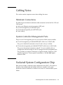
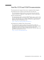
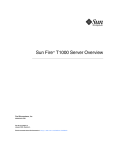
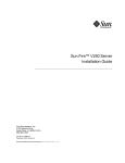
1
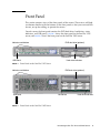
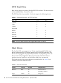
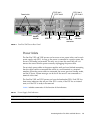
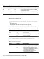
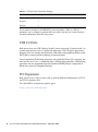
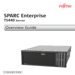
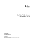
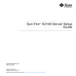
Sun Fire™ V215 and V245 Servers
Getting Started Guide
Sun Microsystems, Inc.
www.sun.com
Part No. 819-3041-10
September 2006, Revision 04
Submit comments about this document at: http://www.sun.com/hwdocs/feedback
Copyright 2006 Sun Microsystems, Inc., 4150 Network Circle, Santa Clara, California 95054, U.S.A. All rights reserved.
Sun Microsystems, Inc. has intellectual property rights relating to technology that is described in this document. In particular, and without
limitation, these intellectual property rights may include one or more of the U.S. patents listed at http://www.sun.com/patents and one or
more additional patents or pending patent applications in the U.S. and in other countries.
This document and the product to which it pertains are distributed under licenses restricting their use, copying, distribution, and
decompilation. No part of the product or of this document may be reproduced in any form by any means without prior written authorization of
Sun and its licensors, if any.
Third-party software, including font technology, is copyrighted and licensed from Sun suppliers.
Parts of the product may be derived from Berkeley BSD systems, licensed from the University of California. UNIX is a registered trademark in
the U.S. and in other countries, exclusively licensed through X/Open Company, Ltd.
Sun, Sun Microsystems, the Sun logo, Sun Fire, Java, J2EE, OpenBoot, and Solaris are trademarks or registered trademarks of Sun
Microsystems, Inc. in the U.S. and in other countries.
All SPARC trademarks are used under license and are trademarks or registered trademarks of SPARC International, Inc. in the U.S. and in other
countries. Products bearing SPARC trademarks are based upon an architecture developed by Sun Microsystems, Inc.
The OPEN LOOK and Sun™ Graphical User Interface was developed by Sun Microsystems, Inc. for its users and licensees. Sun acknowledges
the pioneering efforts of Xerox in researching and developing the concept of visual or graphical user interfaces for the computer industry. Sun
holds a non-exclusive license from Xerox to the Xerox Graphical User Interface, which license also covers Sun’s licensees who implement OPEN
LOOK GUIs and otherwise comply with Sun’s written license agreements.
U.S. Government Rights—Commercial use. Government users are subject to the Sun Microsystems, Inc. standard license agreement and
applicable provisions of the FAR and its supplements.
DOCUMENTATION IS PROVIDED "AS IS" AND ALL EXPRESS OR IMPLIED CONDITIONS, REPRESENTATIONS AND WARRANTIES,
INCLUDING ANY IMPLIED WARRANTY OF MERCHANTABILITY, FITNESS FOR A PARTICULAR PURPOSE OR NON-INFRINGEMENT,
ARE DISCLAIMED, EXCEPT TO THE EXTENT THAT SUCH DISCLAIMERS ARE HELD TO BE LEGALLY INVALID.
Copyright 2006 Sun Microsystems, Inc., 4150 Network Circle, Santa Clara, Californie 95054, Etats-Unis. Tous droits réservés.
Sun Microsystems, Inc. a les droits de propriété intellectuels relatants à la technologie qui est décrit dans ce document. En particulier, et sans la
limitation, ces droits de propriété intellectuels peuvent inclure un ou plus des brevets américains énumérés à http://www.sun.com/patents et
un ou les brevets plus supplémentaires ou les applications de brevet en attente dans les Etats-Unis et dans les autres pays.
Ce produit ou document est protégé par un copyright et distribué avec des licences qui en restreignent l’utilisation, la copie, la distribution, et la
décompilation. Aucune partie de ce produit ou document ne peut être reproduite sous aucune forme, par quelque moyen que ce soit, sans
l’autorisation préalable et écrite de Sun et de ses bailleurs de licence, s’il y en a.
Le logiciel détenu par des tiers, et qui comprend la technologie relative aux polices de caractères, est protégé par un copyright et licencié par des
fournisseurs de Sun.
Des parties de ce produit pourront être dérivées des systèmes Berkeley BSD licenciés par l’Université de Californie. UNIX est une marque
déposée aux Etats-Unis et dans d’autres pays et licenciée exclusivement par X/Open Company, Ltd.
Sun, Sun Microsystems, le logo Sun, Sun Fire, Java, J2EE, OpenBoot, et Solaris sont des marques de fabrique ou des marques déposées de Sun
Microsystems, Inc. aux Etats-Unis et dans d’autres pays.
Toutes les marques SPARC sont utilisées sous licence et sont des marques de fabrique ou des marques déposées de SPARC International, Inc.
aux Etats-Unis et dans d’autres pays. Les produits portant les marques SPARC sont basés sur une architecture développée par Sun
Microsystems, Inc.
L’interface d’utilisation graphique OPEN LOOK et Sun™ a été développée par Sun Microsystems, Inc. pour ses utilisateurs et licenciés. Sun
reconnaît les efforts de pionniers de Xerox pour la recherche et le développement du concept des interfaces d’utilisation visuelle ou graphique
pour l’industrie de l’informatique. Sun détient une license non exclusive de Xerox sur l’interface d’utilisation graphique Xerox, cette licence
couvrant également les licenciées de Sun qui mettent en place l’interface d ’utilisation graphique OPEN LOOK et qui en outre se conforment aux
licences écrites de Sun.
LA DOCUMENTATION EST FOURNIE "EN L’ÉTAT" ET TOUTES AUTRES CONDITIONS, DECLARATIONS ET GARANTIES EXPRESSES
OU TACITES SONT FORMELLEMENT EXCLUES, DANS LA MESURE AUTORISEE PAR LA LOI APPLICABLE, Y COMPRIS NOTAMMENT
TOUTE GARANTIE IMPLICITE RELATIVE A LA QUALITE MARCHANDE, A L’APTITUDE A UNE UTILISATION PARTICULIERE OU A
L’ABSENCE DE CONTREFAÇON.
Please
Recycle
Contents
Servers Overview
1
Server Installation Process
Site Preparation
3
4
Physical Specifications
5
Environmental Requirements
5
Operating Environment
6
Airflow Considerations
7
Acoustic Noise
7
Operating Power Limits and Ranges
7
Calculating Power Consumption
8
Calculating Heat Dissipation
Shipping Kit Contents
Front Panel
8
9
DVD Dual Drive
Hard Drives
10
10
Power and Locator Buttons
Status Indicators
Front USB Ports
Rear Panels
8
11
11
12
12
iii
Power Inlets
13
Network Connectors
Ethernet Ports
Serial Ports
15
15
USB 2.0 Ports
PCI Expansion
Cabling Notes
14
16
16
17
Minimum Connections
17
System Controller Management Ports
Socketed System Configuration Chip
Preinstalled Software
17
17
18
Solaris Operating System
18
Java Enterprise System Software
OpenBoot PROM Diagnostics
19
20
Sun Advanced Lights Out Manager
20
System Reliability, Availability, and Serviceability
Hot-Swappable Components
21
Power Supply Redundancy
22
Environmental Monitoring
22
Sun Fire V215 and V245 Documentation
Documentation, Support, and Training
Third-Party Web Sites
24
24
Sun Welcomes Your Comments
iv
23
24
Sun Fire V215 and V245 Servers Getting Started Guide • September 2006
21
Introducing the Sun Fire V215 and
V245 Servers
This guide provides you with a starting point for getting started with the Sun Fire™
V215 and V245 servers. This guide also includes links to the resources available for
these servers, instructions for planning the installation of a Sun Fire V215 or V245
server, and information for locating the cable connections, configuring the server
and preinstalled software, and finding more information about these servers.
Servers Overview
The Sun Fire V215 and V245 servers represent follow on products of the Sun Fire
V210 and V240 servers and introduce several new features:
■
■
■
■
■
■
■
UltraSPARC® IIIi CPUs
PCI-Express I/O boards
SAS hard drives
Hot-swap fans
Hot-swap power supplies
Dynamic FRU ID
ALOM Secure Shell and SNMP support
The Sun Fire V215 and V245 servers can be mounted in a standard 19 inch rack, and
they ship with the Solaris™ 10 Operating System (OS), the Java™ Enterprise System,
and the Advanced Lights Out Manager (ALOM) software preinstalled as a software
image on the boot drive.
These servers have the following platform names:
■
■
SUNW,Sun-Fire-V215
SUNW,Sun-Fire-V245
1
Both servers have the following common features:
■
■
■
■
■
■
■
■
■
One or two CPUs
One megabyte of L2 cache
Eight DDR-1 DIMM slots
Four 10/100/1000 megabit Ethernet ports
Two USB 2.0 connectors on the rear panel
One DVD dual drive (optional)
One or two redundant power supplies
One ALOM management controller with a serial and 10/100 megabit Ethernet
port
Solaris 10 6/06, plus mandatory patches, as the minimum level operating system
The servers have the following differentiating features:
TABLE 1
Server Differentiating Features
Sun Fire V215
Sun Fire V245
Height
1 rack unit
2 rack units
PCI-X expansion
1
1
PCI-E expansion
2
2
Front USB connectors
1
2
Hard drive bays
2
4
For a detailed list of features, available configurations, and compatible options, go
to:
http://www.sun.com/servers/
For detailed information about these servers, go to:
http://sunsolve.sun.com/
See: Sun System Handbook
2
Sun Fire V215 and V245 Servers Getting Started Guide • September 2006
Server Installation Process
This section contains a list of tasks that you must complete during the installation
process. Each task includes a reference to the appropriate instructions. Each task
must be completed in order.
1. Preparing the site according to the power, clearance, and environmental
requirements.
If you are installing the server into a new Sun™ rack, you must fully prepare the
site for the installation. If you are installing the server into an existing rack, you
must conduct some site preparation to satisfy the additional power and
environmental requirements. See “Site Preparation” on page 4 for specific
instructions.
2. Downloading the appropriate documentation.
You will need to download the Sun Fire V215 and V245 Servers Installation Guide
and the Sun Fire V215 and V245 Servers Product Notes before you attempt to install
the server. You can obtain these documents and other guides associated with
these servers at:
http://www.sun.com/documentation
3. Verifying that you have received all of the components.
The Sun Fire server ships in several packages. See “Shipping Kit Contents” on
page 8 for a list of the shipping kit.
4. Installing the server into the rack.
The installation of the rack slides and cable management arm (CMA) represent
the majority of physical work during the installation.
5. Setting up a console to communicate with the server.
To set up the console, refer to the Sun Fire V215 and V245 Servers Installation Guide
for instructions.
Introducing the Sun Fire V215 and V245 Servers
3
6. Obtaining the latest configuration instructions for your server.
After you power the server on, you will automatically be taken through the
Solaris OS configuration procedure. Therefore, before you power on the server, go
to the following site to obtain the latest configuration details:
http://www.sun.com/software/preinstall/index.xml
7. Powering on the server and configuring the preinstalled software.
The Solaris OS and the Java Enterprise System software are preinstalled on the
server.
To power on the server and configure the preinstalled software, refer to the Sun
Fire V215 and V245 Servers Installation Guide for instructions.
8. Obtaining the latest updates and patches.
Use the appropriate links on the preinstalled software site to obtain the latest
updates and patches.
9. Setting the desired OpenBoot™ PROM configuration options.
The initial boot will test the entire system. You can change the level of testing by
using the OpenBoot PROM commands and configuration variables. To change the
boot test level and other boot variables, refer to the OpenBoot PROM Enhancements
Diagnostics Operation.
10. (Optional) Loading additional software from the Solaris OS media kit.
The Solaris OS media kit is sold separately. The kit includes several CDs
containing software to help you operate, configure, and administer your server.
Refer to the documentation provided in the media kit for a complete listing of
included software and detailed instructions.
Site Preparation
Before you install the Sun Fire server, you must prepare the site. This section
includes information and links to information you need to prepare the site.
4
Sun Fire V215 and V245 Servers Getting Started Guide • September 2006
Physical Specifications
TABLE 2 shows the physical specifications for the Sun Fire V215 and V245 servers.
TABLE 2
Physical Specifications
Sun Fire V215 server
Sun Fire V245 server
Dimension
Value
Height
42.7 mm
Width
440.3 mm
Depth
635.0 mm
Weight
15 kg
Height
87.36 mm
Width
440.3 mm
Depth
635.0 mm
Weight
18 kg
Environmental Requirements
You can operate and store the system safely in the conditions detailed in TABLE 3.
TABLE 3
Operating and Storage Specifications
Specification
Operating
Storage
Ambient temperature
-10˚ C to 35˚ C
maximum ambient
temperature is derated by 1˚ C
(V245) and 2˚ C (V215) per 500
m altitude above 500 m
-40˚ C to 65˚ C
Relative humidity
5% to 80% RH noncondensing,
27˚ C maximum wet bulb
5% to 95% RH noncondensing,
27˚ C maximum wet bulb
Altitude
0 m up to 3000 m (at 35˚ C
ambient)
0 m up to 12000 m
Introducing the Sun Fire V215 and V245 Servers
5
Operating Environment
Your environmental control system must provide intake air for the server that
complies with the limits specified in “Environmental Requirements” on page 5.
To avoid overheating, do not direct warmed air:
■
■
Toward the front of the cabinet or rack.
Toward the server access panels.
Note – When you receive your system, leave it in the environment in which you
will install it for 24 hours. This helps prevent thermal shock and condensation.
The operating environmental limits in TABLE 3 reflect the limits to which the servers
have been tested to meet all functional requirements. Operating computer
equipment in extremes of temperature or humidity increases the failure rate of
hardware components. To minimize the chance of component failure, use the server
within the optimal temperature and humidity ranges.
Ambient Temperature
An ambient temperature range of 21˚ C to 23˚ C is optimal for server reliability. At
22˚ C it is easy to maintain safe relative humidity levels. Operating in this
temperature range provides a buffer in the event of the environmental support
systems failing.
Ambient Relative Humidity
Ambient relative humidity levels between 45% and 50% are the most suitable for
data processing operations to:
■
■
■
Prevent corrosion.
Provide an operating time buffer in the event of environmental control system
failure.
Help avoid failures caused by the intermittent interference from static discharges
that occur when relative humidity is too low.
Electrostatic discharge (ESD) is easily generated and less easily dissipated in areas
where the relative humidity is below 35%, and it becomes critical when levels drop
below 30%.
6
Sun Fire V215 and V245 Servers Getting Started Guide • September 2006
Airflow Considerations
The Sun Fire V215 and V245 servers self-cool when operated in still air.
■
Ensure unobstructed airflow through the chassis.
■
■
Sun Fire V215 servers use internal fans that can achieve a total airflow of 30
cfm in normal operating conditions.
Sun Fire V245 servers use internal fans that can achieve a total airflow of 60
cfm in normal operating conditions.
■
Ensure that inlet air enters at the front of the server and exits from the back.
■
Ventilation openings for both the inlet and exhaust of the system should provide:
■
■
■
Sun Fire V215 server – a minimum open area of 85 cm2 (13 in2) each
Sun Fire V245 server – a minimum open area of 170 cm2 (26 in2) each
Allow a minimum of 88.9 mm (3.5 inches) clearance at the front and rear of the
server when mounted, unless an unobstructed airflow can be ensured.
Acoustic Noise
TABLE 4 shows the amount of acoustic noise generated by the Sun Fire V215 and
V245 servers.
TABLE 4
Acoustic Noise
Server
Noise Generated
Sun Fire V215 server
Less than 80 dBA sound power in ambient temperature of up to 24˚
C, measured on a standalone system to ISO 9296 requirements
Sun Fire V245 server
Less than 80 dBA sound power in ambient temperature of up to 24˚
C, measured on a standalone system to ISO 9296 requirements
Operating Power Limits and Ranges
TABLE 5 shows the operating power for the Sun Fire V215 and V245 servers.
TABLE 5
Operating Power Limits and Ranges
Description
Sun Fire V215 Server
Sun Fire V245 Server
Operating input voltage range
90 - 264 volts
90 - 264 volts
Introducing the Sun Fire V215 and V245 Servers
7
TABLE 5
Operating Power Limits and Ranges
Description
Sun Fire V215 Server
Sun Fire V245 Server
Operating frequency range
47 - 63 Hz
47 - 63 Hz
Maximum operating current
8 Amps @ 90 VAC
8 Amps @ 90 VAC
Maximum AC input
670 watts
670 watts
Calculating Power Consumption
The estimated power consumed in a fully powered server depends on the
configuration of the server. For more information on calculating power
consumption, contact your Sun sales representative.
Calculating Heat Dissipation
To calculate the heat generated by a server so that you can estimate the heat your
cooling system must dissipate, convert the figure for the server’s power requirement
from Watts to BTU/hr. A general formula for doing this is to multiply the power
requirement figure in Watts by 3.412.
Shipping Kit Contents
The server is supplied with the components described in the following list:
■
■
■
Rackmount kit
Cat5 RJ-45 cable
Accessories kit:
■
RJ-45 adaptor
■
Sun Fire V215 and V245 Getting Started Guide (819-3041)
■
Important Safety Information for Sun Servers (816-7190)
■
Sun Server Documentation (819-4953)
■
Entitlement for Solaris 10 6/06 (819-5836)
■
Software License Agreement (819-0764)
Note – The contents of the shipping kit might vary, depending on any options that
you have ordered. Ensure that all the basic parts, as described in the list, are present
in the shipping kit. If any component is missing, contact your Sun sales
representative.
8
Sun Fire V215 and V245 Servers Getting Started Guide • September 2006
Front Panel
This section contains views of the front panels of the servers. These views will help
you become familiar with the features on the front panels so that you can install the
servers, set up the cabling, or operate the servers.
On each server, the front panel contains the DVD dual drive, hard drives, status
indicators, and USB port(s). FIGURE 1 shows the front panel on the Sun Fire V215
server, and FIGURE 2 shows the front panel on the Sun Fire V245 server.
Indicators and buttons
DVD dual drive (optional)
Hard drive 0
USB Port 2
FIGURE 1
Hard drive 1
Hard drive indicators
Front Panel on the Sun Fire V215 Server
Indicators and buttons
USB ports
DVD dual drive (optional)
Drive 2
Drive 3
Drive 0
Drive 1
Hard drives
Hard drive indicators
3
2
FIGURE 2
Front Panel on the Sun Fire V245 Server
Introducing the Sun Fire V215 and V245 Servers
9
DVD Dual Drive
Both servers support an optional, slim-line IDE DVD dual drive. The drive connects
to the motherboard by a custom flex cable.
The DVD dual drive is powered by 5 volts and supports the following formats:
TABLE 6
Supported Formats for the DVD Dual Drive
Media Types
Read
Write
CD-ROM
X
CD-R
X
X
CD-RW
X
X
DVD-ROM
X
DVD-R
X
X
DVD+R
X
X
DVD-RW
X
X
DVD+RW
X
X
Note – The DVD dual drive does not support dual-layer DVD disks.
Hard Drives
The Sun Fire V215 server supports two 2.5 inch serial attached SCSI (SAS) hard
drives, and the Sun Fire V245 server supports four 2.5 inch SAS hard drives. The
drives are hot-pluggable. The preparation procedures vary depending on how the
drive is used in the configuration. File systems must be unmounted and raw
partitions must no longer be in use before these hard drives are removed.
Each hard drive has three status indicators associated with it. See TABLE 7 for a
summary of what the indicators mean.
TABLE 7
Indicator
LED color
LED State
Component Status
Removal
Blue
On
Ready to remove
Off
Not ready to remove
On
Being used
Usage
10
Hard Drive Indicators
Amber
Sun Fire V215 and V245 Servers Getting Started Guide • September 2006
TABLE 7
Hard Drive Indicators
Indicator
Activity
LED color
Green
LED State
Component Status
Off
Not used
Flashing
Active SCSI transactions
Off
No activity
Power and Locator Buttons
Both servers have Power buttons on the front panel and rear panels, and they have a
Locator button on the front panel and a Locator LED on the rear panel. The
following list provides descriptions on how these buttons and LEDs operate:
■
When the main power is off, depressing the Power button once signals the power
supply units to turn on the main output (+12 volts).
■
When the main power is on and the Solaris OS is running, depressing the Power
button once initiates a graceful shutdown of the Solaris OS. The system
management processor continues to run because it operates on the 3.3 volt
standby power circuit.
■
When the main power is on and the Solaris OS is running, depressing and
holding down the Power button for four seconds initiates an immediate
shutdown of the server by signaling the power supply units to turn off the main
+12 volt outputs.
■
Depressing the Locator button turns on a flashing white LED.
■
Depressing the Locator button again turns off the Locator LED.
Caution – When power cord is connected, standby power is still present at the
service processor.
Status Indicators
Both servers have indicators on the front panel. The following list contains
descriptions of the indicators:
■
■
Service Required* (amber) – indicates that service is required
Power OK indicator/button* (green) – indicates the state of the server:
■
■
■
■
Off – not running in its normal state
On – powered on and running
Fast blink – running in standby mode
Slow blink – running in a transitory state
Introducing the Sun Fire V215 and V245 Servers
11
■
■
■
Fan Fault (amber) – when on, indicates a fan failure event occurred
PSU Fault (amber) – when on, indicates that a power supply failure event
occurred
Overtemperature (amber) – when on, indicates that a temperature failure event
occurred
* Indicator is provided on the front and rear of the chassis.
Front USB Ports
The Sun Fire V215 server has one USB port (Port 2) on the front panel. The Sun Fire
V245 server has two USB ports (Ports 2 and 3) located on the front panel. The USB
ports on the front panel on the Sun Fire V245 server cannot be used for keyboard or
mouse input devices. With cable lengths of more than 2 meters or for a UDES USB
device, these ports will only support USB 1.1. With cable lengths shorter than 2
meters, these ports will support USB 2.0.
Rear Panels
Before you attach and route the cables, become familiar with the location of the
power inlets and I/O ports on the back of the servers. FIGURE 3 shows the rear panel
for the Sun Fire V215 server, and FIGURE 4 shows the rear panel for the Sun Fire V245
server.
Power inlets
PCI-X slot 1
PCI-E slot 0
Ethernet indicators
Network indicator
3 2 1 0
PSU indicators
NET MGT
SER TTYB
SER MGT
FIGURE 3
12
USB
Sun Fire V215 Server Rear Panel
Sun Fire V215 and V245 Servers Getting Started Guide • September 2006
Ethernet
connectors
System
indicators
PCI-E slot 2
Power inlets
PCI-X slot 3
PCI-X slot 1
PCI-E slot 0
3 2 1 0
PSU indicators
FIGURE 4
Network
indicator
NET MGT SER TTYB
SER MGT
Ethernet
System
indicators
indicators
USB
Ethernet
connectors
Sun Fire V245 Server Rear Panel
Power Inlets
The Sun Fire V215 and V245 servers can have one or two power inlets, one for each
power supply unit (PSU). As long as the server is connected to a power source, the
server is in Standby power mode. The only way to turn the server fully off is to
remove the server from the power source by unplugging the power cable.
Do not attach power cables to the power supplies until you have finished connecting
the data cables and have connected the server to a serial terminal or a terminal
emulator. When the power cables are connected, the server goes into Standby mode,
and the SC boots. System messages can be lost if the server is not connected to a
terminal at this time.
The Sun Fire V245 and V215 servers can have dual redundant PSUs. Each PSU has
three status indicators that tell you if the PSU is active, if the PSU has an internal
error, or if the PSU is ready to be removed.
TABLE 8 includes summaries of the function of the indicators.
TABLE 8
Power Supply Unit Indicators
OK (green)
Fault (amber)
AC (green)
PSU Condition
Off
Off
On
Power is present, and PSU is in standby mode.
Introducing the Sun Fire V215 and V245 Servers
13
TABLE 8
Power Supply Unit Indicators (Continued)
OK (green)
Fault (amber)
AC (green)
PSU Condition
On
Off
On
Power is present, and PSU is active.
Off
On
On
Power is present; however, the PSU has an internal
fault and requires service.
Off
On or Off
Off
PSU has shut down due to internal fault or loss of
power.
Network Connectors
Each network connector has two status indicators. The network status indicators
convey:
■
■
Network link status
Network speed status (does not apply to the NET MGT port)
TABLE 9 includes summaries of what the Network Link Status indicators mean.
TABLE 9
Network Link Indicators
LED color
LED State
Network Link Status
Green
On
Link is established.
Blinking
Link is transferring data.
Off
Link is not established.
TABLE 10 includes summaries of what the network speed indicators mean.
TABLE 10
14
Network Speed Indicator
LED color
LED State
Network Speed Status
Green
On
The network link is established and running at
its maximum supported speed.
Off
• If the network activity indicator is off, the
network link is established but not running
at its maximum supported speed.
• If the network activity indicator is off,
network link is not established.
Sun Fire V215 and V245 Servers Getting Started Guide • September 2006
Ethernet Ports
The Sun Fire V215 and V245 servers each have four autonegotiating
10/100/1000BASE-T Ethernet system domain ports. All of the Ethernet ports use a
standard RJ-45 connector, the transfer rates for which are given in TABLE 11.
TABLE 11
Ethernet Connection Transfer Rates
Connection Type
IEEE Terminology
Transfer Rate
Ethernet
10BASE-T
10 Mbit/s
Fast Ethernet
100BASE-TX
100 Mbits/s
Gigabit Ethernet
1000BASE-T
1000 Mbit/s
In addition, each server has one 10BASE-T Ethernet management domain interface,
labeled NET MGT. For information on configuring this port for managing the server
with ALOM, see the Sun Advanced Lights Out Management (ALOM) Administration
Guide.
Serial Ports
The server has two serial ports, labelled SER MGT and SER TTYB. The SER MGT
port accepts an RJ-45 connector. Use this port only for server management. The port
labeled SER TTYB accepts an RJ-45 connector. Use this port for general purpose,
asynchronous serial data transfer.
For serial devices, use the SER TTYB port and an RJ-45 adaptor with a null modem
cable. This port appears as ttyb in Solaris OS and OpenBoot PROM messages and is
not connected to the SC serial management port.
The default serial connection settings are listed in TABLE 12.
TABLE 12
Default Serial Connection Settings
Parameter
Setting
Connector
SER MGT or SER TTYB
Rate
9600 baud
Introducing the Sun Fire V215 and V245 Servers
15
TABLE 12
Default Serial Connection Settings
Parameter
Setting
Parity
None
Stop bits
1
Data bits
8
If you need to connect to the SER MGT port using either a DB-9 or a DB-25
connector, use an adapter to perform the cross-overs. See the Sun System Handbook
for more information about the cross-overs.
USB 2.0 Ports
Both servers have two USB 2.0 ports (0 and 1) on the rear panel. Use ports 0 and 1 to
connect input devices such as a keyboard and mouse. The USB ports support hotplugging. You can connect and disconnect USB cables and peripheral devices while
the system is running without affecting system operations.
You can perform USB hot-plug operations only while the Solaris OS is running. You
must run the devfsadm -C command after a USB hot-plug operation. USB hot-plug
operations are not supported when the OpenBoot PROM prompt is displayed or
before the system has completed booting.
PCI Expansion
Both servers use a variety of riser cards to provide different combinations of PCI-E
and PCI-X expansion slots.
For a detailed list of expansion options, go to:
http://www.sun.com/servers/
16
Sun Fire V215 and V245 Servers Getting Started Guide • September 2006
Cabling Notes
This section contains important notes about cabling the server.
Minimum Connections
The following list includes the minimum cable connections for the Sun Fire V215 and
V245 servers:
■
■
■
■
At least one Ethernet network connection (NET port)
SC serial management port (SER MGT port)
SC network management port (NET MGT port)
Power cable(s)
System Controller Management Ports
There are two SC management ports for use with the ALOM system controller:
■
SC serial management port (labeled SER MGT) which uses an RJ-45 cable
This port is the default connection to the SC and is always available.
■
SC network management port (labeled NET MGT) which uses an RJ-45 cable
This port is the optional connection to the SC. It is not available until you
configure the network settings for the SC through the serial management port.
This port does not support connections to Gigabit networks. However, it will
correctly negotiate to a lower speed if connected to a 10/100/1000 Gigabit
Ethernet switch.
Socketed System Configuration Chip
Both servers include a socketed system configuration chip (SSCC). This device is
located on the motherboard and enables the user to transport vital system
information from one machine to another in the event of a unrecoverable system
failure.
Introducing the Sun Fire V215 and V245 Servers
17
From an architectural perspective, the SSCC performs a function similar to the
NVRAM or SEEPROM devices used in previous Sun products. The SSCC contains
the following data structures used by the Sun Fire V215 and V245 service processor:
■
■
■
Host ID
Ethernet MAC addresses for all host Ethernet interfaces
Ethernet MAC addresses for ALOM Ethernet interface
Preinstalled Software
The Sun Fire V215 and V245 servers are shipped with the Solaris 10 Operating
System (OS) and the Java Enterprise System software. You must configure the
preinstalled software as part of the installation process. However, before you begin
the configuration process, go to:
http://www.sun.com/software/preinstall/
This site contains the latest information about the preinstalled software and links to
the software updates and patches you must install.
Solaris Operating System
The Solaris 10 OS is preinstalled on both servers and offers the following features:
18
■
Stability, high performance, scalability, and precision of a mature 64-bit operating
system.
■
Support for over 12,000 leading technical and business applications.
■
Solaris Containers – Isolates software applications and services using flexible,
software-defined boundaries.
■
DTrace – Provides comprehensive dynamic tracing framework for tuning
applications and troubleshooting systemic problems in real time.
■
ZFS – Provides a simple administration model.
■
Security – Provides advanced security features designed to protect the enterprise
at multiple levels.
■
Network performance – Completely rewritten TCP/IP stack dramatically
improves the performance and scalability of your networked services.
Sun Fire V215 and V245 Servers Getting Started Guide • September 2006
Java Enterprise System Software
The Java Enterprise System software includes a free 90-day evaluation license for the
following Java Enterprise System software applications:
■
Access Manager – A security foundation that helps manage secure access to an
enterprises’ web applications by offering single sign-on (SSO) as well as enabling
federation across trusted networks.
■
Application Server – Provides a Java 2 Platform, Enterprise Edition (J2EE™
platform) 1.4 compatible platform for developing and delivering server-side Java
applications and web services.
■
Calendar Server – A web-based tool that facilitates team collaboration by enabling
users to manage and coordinate appointments, events, tasks, and resources.
■
Cluster software – Delivers high availability to enterprise system applications.
■
Directory Server – User-management infrastructure for enterprises that manage
high volumes of user information. The Directory Server provides a centralized
repository for storing and managing user profiles and access privileges, as well as
application and network resource information.
■
Directory Proxy Server – Provides secure firewall-like services for the Directory
Server.
■
Instant Messaging – A standards-based, real-time communication and
collaboration application.
■
Message Queue – An enterprise-level message server using a standards-based
(JMS) messaging solution.
■
Messaging Server – A high-performance, highly secure messaging platform that
provides security features that help ensure the integrity of communications.
■
Portal Server – Provides portal services that identify users through centralized
identity services using roles and policies.
■
Web Server – A secure, reliable, easy-to-use web server designed for medium and
large business applications.
To gain the benefits of the Java Enterprise System, you can buy a subscription license
for a Java Enterprise System Suite or a combination of Java System Suites.
Introducing the Sun Fire V215 and V245 Servers
19
OpenBoot PROM Diagnostics
With the upgrade to OpenBoot PROM 4.18.5 or a subsequently compatible version of
the OpenBoot PROM, diagnostics are enabled by default. This ensures complete
diagnostic test coverage on the initial boot and after error reset events. This change
results in increased boot time.
To change the system defaults and diagnostic settings after the initial boot, refer to
OpenBoot PROM Enhancements for Diagnostic Operation (817-6957). To obtain this
document, go to:
http://www.sun.com/products-n-solutions/hardware/docs/
Sun Advanced Lights Out Manager
The Sun Fire V215 and V245 servers ship with the Sun Advanced Lights Out
Manager (ALOM) software installed. The system console is directed to ALOM by
default and is configured to show server console information on startup.
ALOM enables you to monitor and control your server over either a serial
connection (using the SER MGT port) or Ethernet connection (using the NET MGT
port). For information about configuring an Ethernet connection, refer to the Sun
Advanced Lights Outs Manager User’s Guide.
Note – The ALOM serial port, labeled SER MGT, is for server management only. If
you need a general-purpose serial port, use the serial port labeled SER TTYB.
You can configure ALOM to send email alerts of hardware failures, hardware
warnings, and other events related to the server or to ALOM. ALOM monitors the
following server components:
■
■
■
■
■
■
20
CPU temperature conditions
Hard drive status
Enclosure thermal conditions
Fan speed and status
Power supply status
Voltage conditions
Sun Fire V215 and V245 Servers Getting Started Guide • September 2006
The ALOM circuitry uses standby power from the server. This means that:
■
■
ALOM is active as soon as the server is connected to a power source, and remains
active until power is removed by unplugging the power cable.
ALOM continues to be effective even when the operating system is offline and
when the server is in Standby mode.
For more information about ALOM, see the Sun Advanced Lights Out Management
(ALOM) Administration Guide.
System Reliability, Availability, and
Serviceability
Reliability, availability, and serviceability (RAS) are aspects of a system’s design that
affect its ability to operate continuously and to minimize the time necessary to
service the system. Reliability refers to a system’s ability to operate continuously
without failures and to maintain data integrity. System availability refers to the
ability of a system to recover to an operational state after a failure, with minimal
impact. Serviceability relates to the time it takes to restore a system to service
following a system failure. Together, reliability, availability, and serviceability
features provide for near continuous system operation.
To deliver high levels of reliability, availability, and serviceability, the Sun Fire server
offers the following features:
■
■
■
■
■
■
Hot-pluggable hard drives
Redundant, hot-swappable power supplies
Redundant, hot-swappable fans
Environmental monitoring
Error detection and correction for improved data integrity
Easy access for most component replacements
Hot-Swappable Components
Sun Fire hardware is designed to support hot-swapping of components. You can
install or remove these components while the system is running. Hot-swap
technology significantly increases the system’s serviceability and availability by
providing the ability to replace components without service disruption.
Introducing the Sun Fire V215 and V245 Servers
21
Power Supply Redundancy
Depending on the configuration, the Sun Fire V215 and V245 servers feature two
hot-swappable power supplies, enabling the system to continue operating should
one of the power supplies fail or if one power source fails.
Environmental Monitoring
The Sun Fire servers feature an environmental monitoring subsystem that protects
the server and its components against:
■
■
■
■
Extreme temperatures
Lack of adequate airflow through the system
Power supply failures
Hardware faults
Temperature sensors are located throughout the system to monitor the ambient
temperature of the system and internal components. The software and hardware
ensure that the temperatures within the enclosure do not exceed predetermined safe
operation ranges. If the temperature observed by a sensor falls below a lowtemperature threshold or rises above a high-temperature threshold, the monitoring
subsystem software lights the amber Service Required indicators on the front and
back panel. If the temperature condition persists and reaches a critical threshold, the
system initiates a graceful system shutdown. In the event of a failure of the service
processor, backup sensors protect the system from serious damage, by initiating a
forced hardware shutdown.
All error and warning messages are sent to the service processor system console and
logged in the ALOM console log file. Service Required indicators remain lit after an
automatic system shutdown to aid in problem diagnosis.
The power subsystem is monitored in a similar fashion by monitoring power
supplies and reporting any fault in the front and rear panel indicators.
If a power supply problem is detected, an error message is sent to the service
processor system console and logged in the ALOM console log file. Additionally,
status indicators located on each power supply light to indicate failures. The system
Service Required indicator lights to indicate a system fault.
22
Sun Fire V215 and V245 Servers Getting Started Guide • September 2006
Sun Fire V215 and V245 Documentation
The documentation that supports these servers is comprised of three categories:
■
Documentation that is specific to the Sun Fire V215 and V245 server
This documentation provides hardware and software information about the
features, installation, configuration, usage, diagnostics, and parts replacement.
■
Solaris OS documentation
This documentation applies to other Sun SPARC® based systems as well as to Sun
Fire V215 and V245 servers. This category includes Solaris OS installation, usage,
reference, and release documents, as well as individual man page commands.
Refer to the Solaris OS documentation site:
http://docs.sun.com/app/docs/prod/solaris
■
Documentation for additional Sun software products
This documentation applies to products that are optionally installed and
configured to run on the Sun Fire V215 and V245 servers. This category includes
documentation about Java Enterprise System software products, Sun
Management Center software, Sun Java Desktop System, and others. Refer to the
general Sun documentation web site at:
http://www.sun.com/documentation
Introducing the Sun Fire V215 and V245 Servers
23
Documentation, Support, and Training
Sun Function
URL
Documentation
http://www.sun.com/documentation/
Support
http://www.sun.com/support/
Training
http://www.sun.com/training/
Third-Party Web Sites
Sun is not responsible for the availability of third-party web sites mentioned in this
document. Sun does not endorse and is not responsible or liable for any content,
advertising, products, or other materials that are available on or through such sites
or resources. Sun will not be responsible or liable for any actual or alleged damage
or loss caused by or in connection with the use of or reliance on any such content,
goods, or services that are available on or through such sites or resources.
Sun Welcomes Your Comments
Sun is interested in improving its documentation and welcomes your comments and
suggestions. You can submit your comments by going to:
http://www.sun.com/hwdocs/feedback
Please include the title and part number of your document with your feedback:
Sun Fire V215 and V245 Servers Getting Started Guide, part number 819-3041-10
24
Sun Fire V215 and V245 Servers Getting Started Guide • September 2006