1
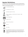
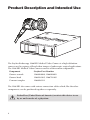
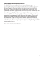
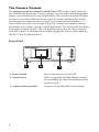
Stryker Endoscopy
5900 Optical Court, San Jose, CA 95138
APPROVALS
DRAWN BY:
01/26/09
S. Livaskani
ORIGINATOR
J. Henley
SIZE
REV.
A
LTR
A
B
C
D
E
F
G
H
J
K
L
M
N
P
R
T
U
V
W
Y
DATE
TITLE
User Manual, 1288HD Video Camera
01/26/09
DOCUMENT NO.
C
ECN NO.
ECO 114767
ECO 115358
ECO 116299
SHEET
OF
1
53
1000-401-140
REVISIONS
DATE
11/12/08
12/08/08
01/26/09
APPROVED
J. Henley
J. Henley
J. Henley
LTR
ECN NO.
REVISIONS
DATE
APPROVED
Printing Instructions
1. Black and White
2. 5.5”W x 8.5”L
3. Select binding and paper weight based on cost
4. Source files are available from Engineering Services
Global Source
Archive this document as a user guide/manual.
This document contains the following languages:
1. English
1288 HD Video Camera
User Guide
REF
1288010000
1288010001
1288210105
1288710105
Contents
Warnings and Cautions....................................... 1
Product Description and Intended Use............... 4
Indications/Contraindications.......................................................5
The Camera Console....................................................................6
The Camera Head.........................................................................8
The C-Mount Coupler...................................................................9
Setup and Interconnection............................... 10
Setting Up the Console...............................................................10
Setting Up the Camera Head......................................................15
Setting Up the Coupler...............................................................16
Operation......................................................... 18
Powering the Camera On/Off.....................................................18
Using the Camera Head Buttons................................................18
Using the Touchscreen Interface................................................20
Controlling Remote Video Accessories......................................25
Using the SFB Serial Interface....................................................25
Using the DVI Fiber Outputs.......................................................25
Operating the Camera with a Light Source....... 26
Troubleshooting............................................... 27
Cleaning, Reprocessing, and Maintenance....... 30
Cleaning the Camera Console....................................................30
Reprocessing the Camera Head.................................................30
Using Sterile Drapes...................................................................35
Replacing the Fuses...................................................................36
Periodic Maintenance Schedule.................................................36
Electromagnetic Compatibility......................... 39
Warranty and Return Policy.............................. 43
Warnings and Cautions
Please read this manual and follow its instructions carefully. The words warning,
caution, and note carry special meaning and should be carefully reviewed:
Warning
Indicates risks to the safety of the patient or user. Failure to
follow warnings may result in injury to the patient or user.
Caution
Indicates risks to the equipment. Failure to follow cautions
may result in product damage.
Note: Provides special information to clarify instructions or present additional
useful information.
An exclamation mark within a triangle is intended to alert the
user to the presence of important operating and maintenance
instructions in the manual.
A lightning bolt within a triangle is intended to warn of the
presence of hazardous voltage. Refer all service to authorized
personnel.
IMPORTANT SAFETY NOTICE: Before operating this device, please read
this operating manual thoroughly and carefully. When using this device
with a light source, fire and/or severe injury may result to the patient, user,
or inanimate objects if the instructions in this manual are not followed.
All light sources can generate significant amounts of heat at the scope tip,
the scope light post, the light cable tip, and/ or near the light cable adapter.
Higher levels of brightness from the light source result in higher levels of
heat. Always adjust the brightness level of the camera and the monitor before
adjusting the brightness level of the light source. Adjust the brightness
level of the light source to the minimum brightness necessary to adequately
illuminate the surgical site. In addition, adjust the internal shutter of the
camera higher in order to run the light source at a lower intensity. Avoid
touching the scope tip or the light cable tip to the patient, and never place
them on top of the patient, as doing so may result in burns to the patient
or user. In addition, never place the scope tip, the scope light post, the light
cable adapter, or the light cable tip on the surgical drapes or other flammable
material, as doing so may result in fire. Always place the light source in
standby mode whenever the scope is removed from the light cable or the
device is unattended. The scope tip, scope light post, light cable adapter,
and light cable tip will take several minutes to cool off after being placed in
standby mode, and therefore may still result in fire or burns to the patient,
user, or inanimate objects.
1
Warnings
To avoid potential serious injury to the user and the patient and/or damage to
this device, please note the following warnings:
1. Carefully unpack this unit and check if any damage occurred during
shipment. If damage is detected, refer to the Warranty and Return Policy
section of this manual.
2. Read this operating manual thoroughly, especially the warnings, and be
familiar with its contents before connecting and using this equipment.
3. Be a qualified physician, having complete knowledge of the use of this
equipment.
4. Test this equipment prior to a surgical procedure. This unit was fully tested
at the factory before shipment. Never use this equipment in the presence of
flammable or explosive gases.
5. Avoid dissembling any part of the camera head, as doing so may break the
seals, causing leakage and/or electric shock.
6. Avoid removing covers on the control unit, as doing so may cause damage to
electronics and/or electric shock.
7. Attempt no internal repairs or adjustments not specifically detailed in this
operating manual.
8. Pay close attention to the care and cleaning instructions in this manual. Any
deviation may cause damage.
9. Never sterilize the camera console, because the delicate electronics cannot
withstand this procedure.
10. Disconnect the control unit from the electrical outlet when inspecting the
fuses.
11. Before each use, check the outer surface of the endoscope to ensure that
there are no rough surfaces, sharp edges, or protrusions.
12. Avoid dropping the camera system. The camera system contains sensitive
parts that are precisely aligned.
13. Ensure that readjustments, modifications, and/or repairs are carried out by
persons authorized by Stryker Endoscopy.
14. Ensure that the electrical installation of the relevant operating room complies
with the NEC and CEC guidelines.
15. To avoid the risk of electric shock, this equipment must only be connected to
a supply mains with protective earth.
16. Multiple portable socket-outlets shall not be placed on the floor.
The warranty is void if any of these warnings are disregarded.
2
Symbol Definitions
In addition to the cautionary symbols already listed, other symbols found on
the 1288 HD Camera and in this manual have specific meanings that clarify the
proper use and storage of the 1288 HD Camera. The following list defines the
symbols associated with this product:
Operating humidity ratings
Operating pressure ratings
Operating temperature ratings
C
US
Denotes compliance to CAN/CSA C22.2 No 601.1- M90
UL60601-1.
Type BF applied part
Equipotentiality
Protective Ground Earth
FireWire
Fuse rating
This symbol indicates that the waste of electrical and electronic
equipment must not be disposed as unsorted municipal waste
and must be collected separately. Please contact the manufacturer
or other authorized disposal company to decommission your
equipment.
3
Product Description and Intended Use
The Stryker Endoscopy 1288 HD Medical Video Camera is a high-definition
camera used to capture still and video images of endoscopic surgical applications.
The 1288 HD Medical Video Camera consists of three main components:
Component
Stryker Part Number
Camera console
1288010000; 1288010001
Camera head
1288210105, 1288710105
C-mount coupler
1288020122
The 1288 HD also comes with various connection cables which, like the other
components, can be purchased together or separately.
Federal law (United States of America) restricts this device to use
by, or on the order of, a physician.
4
Indications/Contraindications
The 1288 HD Camera is indicated for use in general laparoscopy,
nasopharyngoscopy, ear endoscopy, sinuscopy, and plastic surgery wherever a
laparoscope/endoscope/arthroscope is indicated for use. A few examples of
the more common endoscopic surgeries are laparoscopic cholecystectomy,
laparoscopic hernia repair, laparoscopic appendectomy, laparoscopic pelvic
lymph node dissection, laparoscopically assisted hysterectomy, laparoscopic and
thorascopic anterior spinal fusion, anterior cruciate ligament reconstruction,
knee arthroscopy, shoulder arthroscopy, small joint arthroscopy, decompression
fixation, wedge resection, lung biopsy, pleural biopsy, dorsal sympathectomy,
pleurodesis, internal mammary artery dissection for coronary artery bypass,
coronary artery bypass grafting where endoscopic visualization is indicated
and examination of the evacuated cardiac chamber during performance of
valve replacement. The users of the camera are general surgeons, gynecologists,
cardiac surgeons, thoracic surgeons, plastic surgeons, orthopedic surgeons, ENT
surgeons and urologists.
There are no known contraindications.
5
The Camera Console
The camera console or Camera Control Unit (CCU) is the control center for
the 1288 HD Medical Video Camera and processes the video and photographic
images captured during the surgical procedure. The console front panel features
a touch screen, where different menus can be accessed, including the controls
for adjusting the enhancement level, light level, zoom, and white balance, as
well as allows the selection of surgical specialty settings that optimize camera
performance for various, specific surgical procedures. The front panel also allows
activation of remote outputs. The rear panel provides ports for connecting the
1288 HD Camera to viewing and recording equipment, such as video monitors,
the SDC Ultra, or photo printers.
Front Panel
1
2
3
1. Power Switch
Powers the camera ON and OFF
2. Touch Screen
Allows navigation through different menus
for controlling the camera and adjusting the
system settings
3. Camera Connector Port
Connects to the 1288 HD Camera Head
6
Rear Panel
12
1
2 3 4 5 6 7 8 9 10 11
1. SFB Connectors
Enables FireWire connection with Stryker
FireWire devices; provides connection for remote
diagnoses and future software upgrades
2. SIDNE® Port
Connects to the SIDNE® Console to enable voice
operation and/or graphic tablet control
3. Remote Out 1
Connects to a video accessory remote switch
4. Remote Out 2
Connects to a video accessory remote switch
5. S-Video Out
Analog video output
6. DVI Out 1
Digital video output
7. DVI Out 2
Digital video output
8. Display Port
Digital video output
9. AC Power Inlet
Connects to seperable power cord, which can be
used for mains isolation
10. Fuse Panel
Contains two 0.63 A fuses
11. Equipotential
Ground Plug
12. Fiber Outputs
(optical)
DVI output for connection to Lucent connector
fibers (optional: 1288010001)
7
The Camera Head
The camera head connects to the camera console and captures video and
photographic images, which it relays to the camera console. It features several
controls that are accessible through a button keypad located on the top of the
camera head (see the “Operation Instructions” section of this manual).
1
2
3
4
1. Soaking Cap
Protects the cable connector during cleaning and
sterilization
2. Cable Connector
Connects the camera head to the camera console
3. Camera Cable
4. Camera Head
8
Captures photographic and video images, provides
camera controls, and connects with a focusing
coupler
The C-Mount Coupler
The C-Mount coupler threads onto the face of the camera head, enabling a
scope to be attached to the camera. It provides a focusing ring to adjust image
sharpness. The features of the coupler are listed in Figure 3 below. Additional
instructions are available in the “1288 C-Mount Coupler User Guide” (P/N
1000401152).
2
3
4
1
1. Rear Adapter
Threads onto the camera head
2. Focusing Ring
Adjusts the coupler focus
3. Endobody Clamp
Secures the scope to the coupler
4. Scope End
Receives the endoscope
9
Setup and Interconnection
Note: Stryker Endoscopy considers instructional training, or inservice, an
integral part of the 1288 HD Medical Video Camera. Your local Stryker
Endoscopy sales representative will perform at least one inservice at your
convenience to help set up your equipment and instruct you and your staff on its
operation and maintenance. To schedule an inservice, contact your local Stryker
Endoscopy representative after your equipment has arrived.
Setting Up the 1288 HD Camera involves three steps:
1.Setting up the console
2.Setting up the camera head
3.Setting up the coupler
Setting Up the Console
Always connect the camera to an appropriate power source,
using a hospital-grade power cord. Loss of AC power will cause
the camera to shut down and the surgical image to be lost.
Only connect items to the camera that have been specified for
use with the camera. Connecting incompatible equipment may
cause unexpected results.
When the 1288 HD Camera is used with other equipment,
leakage currents may be additive. Ensure that all systems are
installed according to the requirements of IEC 60601- 1-1.
Caution
Equipment which employs RF communications may
affect the normal function of the 1288 HD Camera. When
choosing a location for the 1288 HD Camera, consult the
“Electromagnetic Compatibility” section of this manual to
ensure proper function.
Always set up the console in a location that allows adequate
ventilation (airflow) to the console. Insufficient ventilation may
cause the console to overheat and shut down.
10
To set up the console, make the following connections:
1.Connect the AC power.
• Connect the AC power cord to the AC inlet on the rear console
panel.
• Connect the other end to a hospital-grade outlet.
2.Connect the video output.
• The rear panel provides one analog and three (or four with the
optional fiber digital-video outputs, which can be used together or
independently:
Output Type
Output
Cable
Connector
Analog
*S-VHS 1
S-VHS
4 pin Mini-Din
(push-only connectors)
Digital
**DVI-I1
DVI
29 pin (push-only
connectors, with two
tightening knobs)
**DVI-I2
DVI
29 pin (push-only
connectors, with
two tightening knobs)
Displayport
Displayport
20 pin Displayport
(auto-locking connector)
DVI over
optical Fiber
Fiber (× 4)
Lucent connector fiber
(× 4) (push only)
Optional
* On some monitors, S-VHS inputs may be labeled Y/C.
** The DVI connectors can also output analog SXGA signals through a DVI-I
to VGA adapter.
Use the cables and outputs described above to connect the 1288 HD to other
operating-room equipment. Wiring Diagrams 1-3 describe typical set-ups.
• If desired, connect any remote outputs using the remote cables
supplied with the 1288 HD Camera. (See Wiring Diagram 2.)
Devices connected to the remote outputs of the 1288 HD Camera
can be operated using the P buttons on the camera head and/or
console. See the “Operation Instructions” section of this manual for
details.
•
If desired, connect the SIDNE® interface as well. (See Wiring
Diagram 2.)
11
Wiring Diagram 1: Camera and Flat-Panel Monitor
WiSe 26" HDTV Surgical Display
DVI-I/VGA
Adapter
DVI
DVI
1288 HD Video Camera
12
Wiring Diagram 2: Camera, SDC, SIDNE®, and Flat-Panel Monitor
WiSe 26" HDTV Surgical Display
DVI
SIDNE®
USB
Stryker European Rep. RA/QA Manager
ZAC Satolas Green Pusignan
Av. De Satolas Green
69881 MEYZIEU Cedex, France
DVI
1288 HD Video Camera
REMOTE
SDC
DVI
13
Wiring Diagram 3: Camera, Flat-Panel Monitor, and CRT Monitor
WiSe 26" HDTV Surgical Display
DVI-I/VGA
Adapter
DVI
DVI
1288 HD Video Camera
S-VHS
14
CRT Monitor
Note: If you are using any device with unterminated analog video inputs, you
must connect a cable from the VIDEO OUT of that device to the VIDEO IN on
the monitor.
Note: An additional monitor may be connected using an open camera output.
Note: The camera console is shipped from the factory in NTSC video format.
If necessary, the video format can be changed to PAL by using the “Options”
submenu in the configuration menu. See the “Using the Configuration Menu”
section of this manual.
1.Power on the monitor.
2.Power on the camera.
Note: A color bar pattern will appear on the monitor when the camera head is
not connected to the camera console. Follow the instructions in the “Setting
Up the Camera Head” section of this manual to connect the camera head to the
console.
Setting Up the Camera Head
Caution
Do not severely bend the camera cable or damage may result.
Note: To unplug the camera from the control unit, grasp the knobbed portion of
the connector and pull straight out.
1.Connect the camera head to the console.
• Unscrew the soaking cap from the cable connector if necessary.
• Align the blue arrow on the cable connector with the blue arrow on
the camera-connector port on the front console panel.
• Push in the connector until it locks in place.
15
Setting Up the Coupler
1.Attach the coupler to the camera head.
• Grasping the rear adapter, screw the coupler onto the camera head
(clockwise) until it forms a tight seal.
Before each use, check the outer surface of the endoscope to
ensure there are no rough surfaces, sharp edges, or protrusions.
Caution
When attaching or removing the coupler, grip only the rear
adapter, as twisting other parts of the coupler may result in
mechanical damage.
Do not overtighten the coupler, as this may damage the front
window of the camera.
Do not overtighten a direct-coupled C-mount scope, as this
may damage the front window of the camera.
Note: For direct-coupled C-mount scopes (scopes that require no coupler),
thread the endoscope directly into the camera head until it forms a tight seal.
16
2.Attach an endoscope to the coupler.
• Remove the red dust cap if it is present.
• Push down on the endobody clamp (a) and insert the scope into the
scope end of the coupler (b).
•
Release the endobody clamp.
(a)
(c)
(b)
3.Attach a light cable from the light source to the light post on the endoscope
(c).
17
Operation
Warning: Before using the 1288 HD Camera in a surgical
procedure, test all components to ensure proper function.
Ensure that a video image appears on all video monitors before
beginning any procedure.
Note: Before operating the 1288 HD Camera, ensure all components have been
set up according to the instructions in the “Setup and Interconnection” section of
this manual.
Powering the Camera On/Off
Press the power switch on the console to power the camera on or off.
Using the Camera Head Buttons
The camera head features a cross-shaped, four-button keypad for controlling the
1288 camera. Shown below, these buttons are labeled P, W, Up, and Down.
P
18
W
P (Picture) Button
The P button controls up to two remote video accessories.
• Press the P button for less than two seconds to select Remote 1. One beep
will sound.
• Press the P button for more than two seconds to select Remote 2. Two beeps
will sound.
W (White Balance) Button
The W button activates the white-balance function or the light/zoom function.
The white balance function is used to correct slight color differences that exist
between different light sources or endoscopes.
• Press the W button for less than two seconds to activate the white balance
function.
• Press the W button for more than two seconds to increase the light or zoom
level. The camera console can be set to “light” mode or “zoom” mode using
the Buttons submenu of the Configuration Menu. In “zoom” mode, each W
button press will raise the light level in four steps. In “light” mode, each press
will raise the zoom level in four steps. When either mode has reached its
maximum, pressing the W button again will cycle the level back to the lowest
setting.
Perform the white balance procedure before every surgical procedure.
Note: Ensure that a scope and light source are attached to the camera, and that
the camera, light source and monitor are powered on before adjusting the white
balance.
1.Point the scope at several stacked 4 × 4 white gauze pads, a white laparoscopic
sponge, or any clean white surface.
2. Look at the monitor and make sure that no glare is visible off of the white
surface.
3. Press and hold the W button until “WHITE BALANCE IN PROGRESS”
begins flashing on the video monitor.
4. Continue pointing the scope at the white surface until the video monitor
indicates that white balance is “WHITE BALANCE COMPLETE.” The video
picture may change color. If you cannot achieve an acceptable white balance,
refer to the “Troubleshooting” section of this manual.
19
Up and Down Buttons
The up and down buttons work together to increase or decrease the light/zoom
level.
The camera console can be set to “light” mode or “zoom” mode using the Buttons
submenu of the Configuration Menu. In “light” mode, pressing the arrow buttons
will raise or lower the automatic-shutter light-level setting in 8 steps. In “zoom”
mode, pressing the arrow buttons will raise or lower the zoom level in 8 steps.
Press the arrow button once to adjust the light level by one step or hold down the
button for a quicker transition.
Using the Touchscreen Interface
The touchscreen interface on the console provides controls for operating the
camera and selecting system settings. Controls are located in a series of menus
shown below and described hereafter.
Home
Menu
Language
OSD
LANGUAGE
ENGLISH
20
Home Screen
The Home screen is the default screen. Use the buttons below to choose surgical
specialties, operate the camera head, and navigate to other menus.
Home
Menu
Language
OSD
LANGUAGE
ENGLISH
Scroll through preset camera settings designed for
surgical specialties. Choose from:
•
•
•
•
•
Arthroscopy
Cystoscopy
ENT/Neuro
Flexi-Scope
Hysteroscopy
•
•
•
•
Laparoscopy
Laser
Microscope
Standard
Capture photo.
Press and hold button for two seconds before it
activates.
Capture video.
Press and hold button for two seconds before it
begins recording. Press again to stop.
Activate white balance.
Press and hold button for two seconds before it
activates.
• Press once to proceed to the Menu screen.
• Hold for 5 seconds to proceed to the Main
Menu (on-screen display).
21
Menu Screen
The Menu screen provides options for adjusting the camera picture.
Home
Menu
Language
OSD
LANGUAGE
ENGLISH
• Press once to return to the Home screen.
• Hold for 5 seconds to proceed to the Language
screen.
Increase or decrease:
• Enhance (picture sharpness)
• Light (automatic-shutter light level)
• Zoom (magnification)
Enhance/Light/Zoom Meter
Appears on the monitor, indicating the selection level.
22
Language Screen
The Language screen allows you to choose the default language for the user
interface.
Home
Menu
Language
OSD
LANGUAGE
ENGLISH
LANGUAGE
ENGLISH
Scroll through available interface languages.
Choose from:
•
•
•
•
•
•
•
•
Danish
German
Polish
Dutch
Greek
Portuguese
English
Italian
•
•
•
•
•
•
•
•
Simplified Chinese
Finnish
Japanese
Spanish
French
Korean
Swedish
Norwegian
• Press the Home button to exit the language screen.
Power cycle the unit for the change to take effect.
• To initiate black balance, hold for 5 seconds until
“BLACK BALANCE” begins flashing on the video
monitor.
23
Main Menu Screen (for On-Screen Display)
The Main Menu screen works in conjunction with the on-screen display (OSD)
to provide options for adjusting system settings.
Home
Menu
Language
OSD
LANGUAGE
ENGLISH
• Press once to return to the Home screen and exit OSD.
• Hold for 5 seconds to reset global system settings to
defaults and return to the Home screen. Power cycle the
unit for global settings to take effect.
MAIN MENU
Select up or down in the OSD.
Choose from:
• Shutter
• Options
• Buttons
SHUTTER
OPTIONS
BUTTONS
Proceed to the next (or previous) OSD screen. Choose from:
• OSD Main Menu
• Shutter—to adjust camera shutter settings
• Options—to adjust camera control unit options
• Buttons—to program functions of the camera head
buttons
24
Controlling Remote Video Accessories
The 1288HD Camera can remotely control up to two video accessories (such as
the SDC Ultra, a VCR, or a photo printer), enabling the user to capture images or
start and stop video recording by pressing the P button. (See also the “Using the
Camera Buttons” section of this manual.)
1. Connect the video accessory to one of the remote outputs on the rear console
panel. Use the provided remote cables. (See Wiring Diagram 2 in the “Setting
Up the Console” section of this manual.)
2. Press the P button for less than one second to select Remote 1. One beep will
sound.
3. Press the P button for more than one second to select Remote 2. Two beeps
will sound.
Using the SFB Serial Interface
The SFB serial connection on the console rear panel enables FireWire connection
to the Stryker Endoscopy Software Management Site (SMS). Connect to the
L9000 Light Source for “Run/Standby” controls from the Camera Head.
Note: This system feature is not necessary for regular camera system operation.
This system feature requires an additional device (that is, a computer) to connect
to SMS.
Using the DVI Fiber Outputs
Using controls or adjustments or performing procedures
differently than specified in this manual may result in
hazardous radiation exposure.
The 1288 HD Camera has the optional upgrade, the fiber output, for model
1288010001. This upgrade contains four laser diodes to transmit a DVI output
over fiberoptic cables.
1. Connect four individual fibers (terminated in Lucent connectors) to the red
(R), green (G), blue (B) and clock (C) laser diodes on the console rear panel.
2. Connect the four fibers to a compatible fiberoptic DVI receiver.
• The four fibers should be connected to the camera console in the labeled
order: RGBC
• The fibers should be connected to the monitor in one of two
configurations: CBGR (reverse order) or BGRC (R/B switched).
3. Ensure the fiberoptic output is enabled (on) via the Options Submenu in the
Configuration Menu. (See the section “Using the Configuration Menu”.)
Note: The 1288 HD Camera model 1288010001 is a Class 1 laser product per IEC
60825-1 and 21CFR.
25
Operating the Camera with a Light
Source
IMPORTANT SAFETY NOTICE: Before operating this device,
please read this operating manual thoroughly and carefully.
When using this device with a light source, fire and/or severe
injury may result to the patient, user or inanimate objects, if the
instructions in this manual are not followed. All light sources
can generate significant amounts of heat at the scope tip, the
scope light post, the light cable tip, and/or near the light cable
adapter. Higher levels of brightness from the light source result
in higher levels of heat. Always adjust the brightness level of the
camera and the monitor before adjusting the brightness level of
the light source. Adjust the brightness level of the light source
to the minimum brightness necessary to adequately illuminate
the surgical site. In addition, adjust the internal shutter of
the camera higher in order to run the light source at a lower
intensity. Avoid touching the scope tip or the light cable tip to
the patient, and never place them on top of the patient, as doing
so may result in burns to the patient or user. In addition, never
place the scope tip, the scope light post, the light cable adapter,
or the light cable tip on the surgical drapes or other flammable
material, as doing so may result in fire. Always place the light
source in standby mode whenever the scope is removed from
the light cable or the device is unattended. The scope tip, scope
light post, light cable adapter, and light cable tip will take several
minutes to cool off after being placed in standby mode, and
therefore may still result in fire or burns to the patient, user, or
inanimate objects.
26
Troubleshooting
Problem
Possible Solution
“Restart
Camera
Console”
message
(Color bar
background)
• Camera head temporarily shut down due to overcurrent.
Turn off the console, wait 3 seconds, and turn it back on.
• After sterilization, ensure the camera head has cooled
down before connecting it to the console
“System Error”
message
(Light blue
background)
• No video detected.
• After sterilization, ensure the camera head has cooled
down before connecting it to the console
• Return the system for repair.
No color bar
• Ensure the video-out from the console is connected to
the video-in on the monitor.
• Ensure all video systems are powered on.
• Ensure that the camera head is not connected to the
console.
• Turn off the console, wait 3 seconds, and turn it back on.
No color bar
(Optical DVI
only)
• Same as above.
• See the “Using the DVI Fiber Outputs” section of this
manual.
Incorrect
picture color
• Perform the white balance procedure. (See the “W
Button” section of this manual.)
• Check the color settings on the monitor.
White balance
(WB) quality
not good
• See the solution for “Picture is too dark.”
• See the solution for “Picture is too bright.”
• Perform the white-balance procedure with the light
source connected to the scope. Use metal-halide, xenon,
or LED lighting (no fluorescent lighting).
Picture is too
dark
• Increase the camera light level with the camera head.
• Increase the light-source output.
• Check the fiber-optic light cable for excessive broken
fibers.
Picture is too
bright
• Decrease the camera light level.
• Decrease the light-source output.
• Ensure that Shutter submenu in the Configuration menu
has the following settings:
BRT CNTRL AUTO
Shutter On
27
Noise or snow
on picture
when using
electrocautery
probes
• Plug the electrocautery generator into a separate
electrical outlet and separate the 1288 HD power cord
from the electrocautery power cord.
• Separate the camera cable from the electrocautery cable.
• Reposition the electrocautery grounding pad on the
patient.
Noise or snow
on picture
when not using
electrocautery
probes
• Reduce Enhancement.
• Check for and replace faulty video cables.
No video
• Check to ensure that all devices in the video system are
picture when
plugged in and powered on.
the camera
• Check the connector on the camera-head cable for
head is plugged
broken pins.
in
• Detach the camera head from console and reconnect
• Turn off the console, wait 3 seconds, and turn it back on.
Image is not
well centered
• Release the scope from the coupler and then reconnect
it. Make sure the scope is seated correctly in the coupler.
Variability
in color
reproduction
between
different light
sources or
peripherals
• Perform the white-balance procedure. (See the “W
Button” section of this manual.)
• Check the settings on video peripherals.
• Ensure the light source has a proper infrared filter (check
with manufacturer specifications).
Foggy picture
(loss of
definition and
clarity)
•
•
•
•
28
Refocus the camera.
Refocus the coupler.
Clean and dry both the scope and the coupler windows.
Remove the coupler from the camera head and
remove any moisture that has built up between the two
components.
Problem
Possible Solution
Optics are
dirty
• Rotate the scope. If dust particles in the picture rotate,
the dust is located on the scope itself. Follow the
manufacturer’s instructions for cleaning the eyepiece
and negative lens.
• If particles in the picture do not move when you rotate
the scope, the particles are located on the coupler or
camera. Remove the scope and clean the window on the
front of the coupler with a dry or alcohol-tipped cotton
swab.
• If dust particles lie between the coupler and camera,
remove the coupler and clean the coupler and camera
windows.
• Ensure all components are completely dry before
reassembling them, or fogging may result.
Blurry picture
• Ensure the coupler or C-Mount scope is in focus.
• Increase the enhancement.
• Ensure the specialty switch is not set to FLEXI-SCOPE
unless you are using a flexible scope.
Note: If this troubleshooting guide does not resolve the problem, call Stryker
Technical Support at 1-877-478-7953 (inside the U.S.) or refer to the “Warranty
and Return Policy” section of this manual.
29
Cleaning, Reprocessing, and
Maintenance
The camera console is not intended to come into contact with the patient. It may
be cleaned, but not sterilized. The camera head and coupler may contact the
patient and should both be cleaned and sterilized prior to every use.
Cleaning the Camera Console
Disconnect the console from the AC power source before
cleaning.
Caution
Never immerse or sterilize the camera console as this will
damage the camera and void the warranty.
Should the camera console need cleaning, wipe it down with a sterile cloth and
mild cleaning solution.
Reprocessing the Camera Head
These reprocessing instructions are provided in accordance with ISO 17664.
While they have been validated by the manufacturer of the medical device as
being capable of preparing the device for re-use, it remains the responsibility
of the processor to ensure that the reprocessing as actually performed, using
equipment, materials, and personnel in the reprocessing facility, achieves the
desired result. This normally requires validation and routine monitoring of the
process.
Warnings
• This device must be cleaned and sterilized prior to the first use and after
every subsequent use.
• Use only the sterilization cycles outlined in this document. Using
unspecified sterilization cycles may damage the device or result in
incomplete sterilization.
• Separate the camera head, coupler, and scope prior to cleaning,
disinfection, or sterilization. If the coupler and camera head are cleaned,
disinfected, or sterilized as a single unit, disconnecting the coupler
during use will compromise the sterility of the two products. (Refer to
the coupler and scope product manuals for reprocessing instructions.)
• Wear appropriate protective equipment: gloves, eye protection, etc.
30
Cautions
• Always install the soaking cap prior to processing the camera. Failure
to properly tighten the soaking cap will corrode the connector pins and
void the warranty.
• Inspect the camera cable for cuts and breaks before soaking in any fluid.
Return any damaged camera to Stryker for service.
• Never soak the camera in the same tray with sharp instruments.
• Do not use brushes or pads with metal or abrasive tips during manual
cleaning, as permanent scoring or damage could result.
• To minimize galvanic corrosion, avoid soaking dissimilar metals in close
proximity.
• Only camera heads marked autoclavable can withstand steam
sterilization. Autoclaving camera heads that do not bear this marking
will result in product damage.
• Allow the camera head to cool before connecting it to the console.
Connecting the camera head while it is still hot may result in system
error.
Limitations on Reprocessing
• Do not cross-sterilize the device. Using multiple sterilization methods
may significantly reduce the performance of the device.
• Do not leave the device in solutions longer than necessary. This may
accelerate normal product aging.
• Proper processing has a minimal effect on this device. End of life is
normally determined by wear and damage due to use.
• Damage incurred by improper processing will not be covered by the
warranty.
Instructions
Point of Use
• Wipe excess soil from the device using disposable paper towels.
• If an automated reprocessing method will be used, rinse any channels in
the device with 50mL of sterile distilled water immediately after use.
Containment and Transportation
• Reprocess the device as soon as reasonably practical following use.
• Transport the device in a tray to avoid damage.
31
Preparation for Cleaning
1.Disassemble the coupler from the scope and camera head.
2.Prepare an enzymatic detergent according to the manufacturer’s
recommendations (one ounce per gallon of tap water at 35 - 40°C).
3.Wipe the entire device with the detergent, using a clean cloth.
4.Immerse the device in the detergent. Inject any inside regions of the device
with 50mL of the detergent solution to remove loose debris.
5.Soak the device in the detergent for at least 15 minutes.
Cleaning: Manual
1.Brush
• Thoroughly brush the exterior of the device with a soft-bristled brush,
focusing on any mated or rough surfaces.
• Inject any lumen or mated surface a minimum of five times with at least
50mL of the detergent.
• Brush any lumens a minimum of five times from each end, using an
appropriate bottle brush.
• Brush any movable parts in their extreme open and closed positions.
2.Rinse
• Rinse the device with treated water at ambient temperature to remove all
detergent residue. Flush any lumens or mated surfaces a minimum of 5
times. Once all detergent residues have been removed, continue to rinse
for a minimum of 30 seconds.
• Drain excess water from the device and dry it using a clean cloth or
pressurized air.
• Visually inspect the device for cleanliness, paying close attention to
hard-to-reach areas. If visible soil remains, repeat steps 1 and 2.
3. Soak
• Prepare a non-enzymatic detergent, according to the manufacturer’s
recommendations of 0.25 ounces/gallon tap water at 35 - 40°C.
• Fully immerse the device and inject any lumens and mated surfaces with
at least 50mL of the detergent.
• Soak the device for a minimum of 15 minutes.
32
4.Brush
• Thoroughly brush the exterior of the device using a soft-bristled brush.
• Inject the prepared detergent into any cannulae, lumens, or mated
surfaces a minimum of 5 times.
• Brush any lumens a minimum of 5 times from each end, using an
appropriate bottle brush.
• Actuate the device, brushing around any movable parts in all extreme
positions.
5.Rinse
• Thoroughly rinse the device with treated water until all detergent
residue is removed. Flush any lumens or crevices 5 times. After the
detergent residue is removed, continue rinsing for a minimum of 30
seconds.
• Drain the excess water from the device and dry it with a clean cloth or
pressurized air.
Cleaning: Automated
1.Brush
• Brush both ends of any lumens a minimum of five times, using an
appropriate bottle brush.
2.Rinse
• Rinse the device with treated water at ambient temperature until there
is no visible detergent residue. Continue to rinse for a minimum of 30
seconds after all detergent residue has been removed.
• Place the device in the washer on an incline to facilitate drainage.
3.Automated wash
• Program the washer using the following parameters:
Phase
Recirculation
Time
Water
Temperature
Detergent Type and
Concentration
(if applicable)
Pre Wash
2 minutes
Cold
N/A
Enzyme
Wash
2 minutes
Hot
Enzymatic Detergent
Wash 1
2 minutes
Set point
(66˚C)
Regular Detergent
Rinse 1
2 minutes
Hot
N/A
Dry Phase
7 minutes
115˚C
N/A
*If necessary, use pressurized air to aid in drying. Visually inspect each device
for cleanliness.
33
Disinfection (optional)
1.Disinfect the device by submerging it in a disinfection agent. Follow
the disinfection agent manufacturer’s recommended concentrations,
temperatures, and exposure times. Acceptable disinfection agents contain:
• ≥ 2.4% glutaraldehyde
or
• ≥ 0.55% ortho-phthalaldehyde.
2.Thoroughly rinse and flush all parts and lumens with running,
demineralized water to remove the disinfectant.
3.Dry all parts with a lint-free towel immediately after rinsing.
Drying
• For automated drying, use the drying cycle provided with the washer/
disinfector.
• For manual drying, use a lint-free cloth.
• Dry any lumens with compressed air.
Maintenance, Inspection, and Testing
• Inspect the device on a continual basis. If a problem is observed or
suspected, the device should be returned for repair.
• Inspect all components for cleanliness. If fluid or tissue buildup is
present, repeat the above cleaning and disinfection procedures.
• Inspect the camera cable for cuts and breaks. Return any damaged
camera to Stryker for service.
Packaging
N/A
Sterilization
After performing the cleaning instructions specified above, perform one of the
following sterilization cycles.
34
Ethylene Oxide (EtO)
Preconditioning parameters
Temperature
55 ± 2°C (131 ± 5°F)
Exposure
Concentration (100% EtO)
725 mg/L
Temperature
55 ± 2°C (131 ± 5°F)
Time
1 hour
Chamber Humidity
70% RH (50–80%) ± 5%
Aeration parameters
Aeration Time
12 hours
Temperature
35–54°C (95–130°F)
Steris System 1
1.Clean and prepare the camera head and cable as recommended in the
Cleaning and Disinfection sections. Ensure the soaking cap is installed.
2.Sterilize the camera head and cable using Steris® System 1 with Steris®
Sterilant 20.
3.Allow the camera head, cable, coupler, and scope to completely dry before
reassembly. Any moisture on the threads will cause the camera and coupler
windows to fog during use.
Sterrad
1.Clean and prepare the camera head and cable as recommended in the
“Cleaning and Sterilization” section. Ensure the soaking cap is installed.
2.Sterilize the camera head and cable using the Sterrad™ NX or 100s
Sterilization System.
3.Allow the camera head, cable, coupler, and scope to completely dry before
reassembly. Any moisture on the threads will cause the camera and coupler
windows to fog during use.
Storage
N/A
Using Sterile Drapes
Using sterile drapes will ensure maximum longevity of your 1288 HD
Camera Head. For best results, follow the instructions provided by the drape
manufacturer. Sterile camera drapes for use with the 1288 HD Camera Head can
be ordered under Stryker product number 240-010-200.
35
User Maintenance
Replacing the Fuses
To avoid the risk of fire, use only fuses of the value specified on
the fuse label located on the rear panel of the transmitter.
1.Unplug the power cord from the wall outlet and remove the cord from the
transmitter console.
2.Unlatch the fuse holder above the AC inlet and remove it. (You may need
to press the tab on the fuse holder with a slender screwdriver to release the
latch.)
3.Replace the fuse with the same value and rating.
4.Reinstall the fuse holder until the tab snaps in place.
Periodic Maintenance Schedule
To ensure safe operation of the Model 1288 HD Video Camera
you should periodically perform the following procedure:
Every 12 months, check the earth leakage current to <500µA (<300µA in U.S.A.),
ground protective earth impedance to <0.1 ohms, and power consumption
less than or equal to rated power. Use a true RMS digital multimeter and safety
analyzer to perform this test.
Note: Refer calibration and operating difficulties not detailed in this manual to
your Stryker Endoscopy sales representative.
Disposal
This product contains electrical waste or electronic equipment.
It must not be disposed of as unsorted municipal waste and
must be collected separately in accordance with applicable
national or institutional related policies relating to obsolete
electronic equipment.
The 1288 HD must be disposed of according to local laws and hospital practices.
36
Technical Specifications
60Hz settings are displayed first. (50Hz settings follow in parentheses.)
Imaging System
1/3” Progressive Scan CCDs
High Definition
Scanning System
Horizontal: 64.00 kHz (60.00 kHz)
Vertical: 60.02 Hz (50.00 Hz)
Video Outputs
Digital/
Analog:
Two Digital Video Interface
(DVI)/RGBHV
1280 × 1024 (HD), 720p, 1080p
(HDTV) format
Connector:
29-pin DVI-I
Y/C:
One S-VHS
Connector:
4-pin mini-DIN
Digital Fiber: HD, HDTV (R, G, B, Clk)
Connector:
Four Lucent fiber connectors
with 1.25 mm ferrules
Digital
One Displayport 1280 × 1024
(HD), 720p, 1080p (HDTV)
format
Connector
20 pin Displayport
Mounting
Endoscope eyepiece used with C-mount coupler
C-mount camera head used with C-mount
scopes
(C-mount coupler/scope thread: 1-32" UN 2A)
Auto Shutter Range
1/60 (1/50) – 1/50,000 second
Operating Conditions
Temperature: 5 – 40°C
Relative Humidity: 30 – 95%
Transport and Storage
Conditions
Temperature: -10 – 60°C
Relative Humidity: 10 – 75%
Atmospheric Pressure: 700 – 1060 hPa
Input Electrical Ratings
100 – 240VAC ± 10% (0.6A) @ 47 – 63Hz
37
Total Shipping Weight
13 lbs. (6.0 kg) Camera console
0.5 lbs. (0.226 kg) Coupler
1.5 lbs. (0.680 kg) Camera head
Dimensions
Camera Console:
12.5” w × 4.0” h × 15.25” d
(31.8 cm w × 10.2 cm h × 38.7 cm d)
Camera Head Cable to Camera Console:
10.3 ft (3.15 m) sealed cable
20.7 ft (6.30 m) cable extension available
Enhancement
16 levels (switchable)
Classification
Class I Equipment
Type BF Applied Part
Water Ingress Protection, IPX0—Ordinary
Equipment
Continuous Operation
Complies with Medical
Safety Standards
IEC 60601-1:1988 + A1:1991 + A2:1995
IEC 60601-2-18:1996 + A1:2000
CAN/CSA C22.2 No 601.1-M90
UL 60601-1:2003
AS/NZS 3200.1.0:1998
CSA 22.2.601.1.1:2002
CAN/CSA C22.2 No. 601.2.18:1990
Complies with Medical
EMC Standard
IEC 60601-1-2:2001 + A1:2004
Complies with Laser
Product Standards
Class 1 Laser Product
Contains four 850-nm laser diodes
This product complies with IEC 608251:1993+A1:1997+A2:2001.
This product complies with 21CFR, Subchapter
J, Parts 1040.10 and 1040.11, except for
deviations pursuant to Laser Notice No. 50,
dated July 26, 2001.
Please contact your local Stryker Endoscopy sales representative for information
on changes and new products.
38
Electromagnetic Compatibility
Like other electrical medical equipment, the 1288 HD Camera requires special
precautions to ensure electromagnetic compatibility with other electrical medical
devices. To ensure electromagnetic compatibility (EMC), the 1288 HD Camera
must be installed and operated according to the EMC information provided in
this manual.
Note: The 1288HD Camera has been designed and tested to comply with
IEC 60601-1-2:2001 requirements for EMC with other devices.
Do not use cables or accessories other than those provided
with the 1288 HD Camera, as this may result in increased
electromagnetic emissions or decreased immunity to such
emissions.
If the 1288 HD Camera is used adjacent to or stacked with other
equipment, observe and verify normal operation of the 1288
HD Camera in the configuration in which it will be used prior
to using it in a surgical procedure. Consult the tables below for
guidance in placing the 1288 HD Camera.
Caution
Equipment which employs RF communications may affect the
normal function of the 1288 HD Camera.
Guidance and Manufacturer’s Declaration: Electromagnetic Emissions
1288 HD Camera is intended for use in the electromagnetic environment specified below. The
customer or the user of 1288 HD Camera should ensure that it is used in such an environment.
Emissions test
Compliance
Electromagnetic Environment guidance
RF emissions CISPR 11
Group 1
1288 HD Camera uses RF energy only
for its internal function; therefore, its
RF emissions are very low and are not
likely to cause any interference in nearby
electronic equipment.
RF emissions CISPR 11
Class B
Harmonic emissions
Class B
The 1288 HD Camera is suitable for
use in all establishments other than
domestic establishments and those
directly connected to the public lowvoltage power supply network that
supplies buildings used for domestic
purposes, provided the following warning
is heeded:
IEC61000-3-2
Voltage Fluctuations/ flicker
emissions IEC61000-3-3
Complies
Warning: This system is intended
for use by health care professionals
only. This system may cause radio
interference or may disrupt the operation
of nearby equipment. It may be
necessary to take mitigation measures,
such as reorienting or relocating the
system or shielding the location.
39
Guidance and Manufacturer’s Declaration: Electromagnetic Immunity
1288 HD Camera is intended for use in the electromagnetic environment specified below.
The customer or the user of 1288HD Camera should ensure that it is used in such an environment.
Immunity Test
IEC 60601 Test Level
Compliance Level
Electromagnetic
Environment:
Guidance
Electrostatic Discharge
(ESD) IEC61000-4-2
±6kV contact
±2,4,6kV contact
±8kV air
±2,4,8kV air
Floors should be
wood, concrete, or
ceramic tile. If floors
are covered with
synthetic material,
the relative humidity
should be at least
30%.
Electrical fast transient/
burst IEC61000-4-4
±2kV for power supply
lines
±2kV line to ground
±1kV for input/output
lines
±1kV line to line
Surge
±1kV differential mode
IEC61000-4-5
±2kV common mode
Voltage dips, short
interruptions and
voltage variations on
power supply input lines
<5% Ut (>95% dip in
Ut) for 0.5 cycle
<5% Ut (>95% dip in Ut)
for 0.5 cycle
IEC61000-4-11
40% Ut (60% dip in
Ut) for 5 cycles
40% Ut (60% dip in Ut)
for 5 cycles
70% Ut (30% dip in
Ut) for 25 cycles
70% Ut (30% dip in Ut)
for 25 cycles
<5% Ut (>95% dip in
Ut) for 5 sec.
<5% Ut (>95% dip in Ut)
for 5 sec.
3 A/m
N/A
Power frequency
(50/60Hz) magnetic field
±0.5, 1kV differential
mode
±0.5, 1, 2kV common
mode
IEC 61000-4-8
NOTE: Ut is the AC mains voltage prior to application of the test level.
40
Mains power quality
should be that of a
typical commercial or
hospital environment.
Mains power quality
should be that of a
typical commercial or
hospital environment.
Mains power quality
should be that of a
typical commercial or
hospital environment.
If the user of 1288
HD Camera requires
continued operation
during power mains
interruptions, it is
recommended that
1288 HD Camera
be powered from an
uninterruptible power
supply or a battery.
Power-frequency
magnetic fields
should be at levels
characteristic of a
typical location in a
typical commercial or
hospital environment.
Guidance and Manufacturer’s Declaration: Electromagnetic Immunity
1288 HD Camera is intended for use in the electromagnetic environment specified below.
The customer or the user of 1288 HD Camera should ensure that it is used in such an environment.
Immunity Test
IEC 60601 Test Level
Compliance
Level
Electromagnetic Environment:
Conducted RF
3 Vrms
3V
IEC 61000-4-6
150 kHz to 80 MHz
3 V/m
Radiated RF
3 V/m
IEC 61000-4-3
80MHz to 2.5 GHz
Portable and mobile RF
communications equipment
should be used no closer to any
part of the 1288 HD Camera
system, including its cables, than
the recommended separation
distance calculated from the
equation applicable to the
frequency of the transmitter.
Guidance
Recommended Separation
Distance
d = 1.17 √P
d = 1.17 √P
80 MHz to 800 MHz
d = 2.23 √P
GHz
800 MHz to 2.5
where P is the maximum output
power rating of the transmitter
in watts (W) according to the
transmitter manufacturer and d
is the recommended separation
distance in meters (m).
Field strengths from fixed RF
transmitters, as determined
by an electromagnetic site
survey (a), should be less than
the compliance level in each
frequency range(b). Interference
may occur in the vicinity of
equipment marked with the
following:
NOTE 1: At 80 MHz and 800 MHz, the higher frequency range applies.
NOTE 2: These guidelines may not apply in all situations. Electromagnetic propagation is affected by
absorption and reflection from structures, objects, and people.
41
Guidance and Manufacturer’s Declaration: Electromagnetic Immunity
1288 HD Camera is intended for use in the electromagnetic environment specified below.
The customer or the user of 1288 HD Camera should ensure that it is used in such an environment.
(a) Field strengths from fixed transmitters, such as base stations for radio (cellular/cordless)
telephones and land mobile radios, amateur radio, AM and FM radio broadcast, and TV broadcast,
cannot be predicted theoretically with accuracy. To assess the electromagnetic environment due to
fixed RF transmitters, an electromagnetic site survey should be considered. If the measured field
strength in the location in which the 1288 HD Camera system is used exceeds the applicable RF
compliance level above, the 1288 HD Camera system should be observed to verify normal operation.
If abnormal performance is observed, additional measures may be necessary, such as reorienting or
relocating the 1288 HD Camera unit.
(b) Over the frequency range 150 kHz to 80 MHz, field strengths should be less than 3 V/m.
Recommended Separation Distances Between Portable and Mobile RF Communications
Equipment and the 1288 HD Camera System
The 1288 HD Camera system is intended for use in an electromagnetic environment in which
radiated RF disturbances are controlled. The user of the 1288 HD Camera system can help prevent
electromagnetic interference by maintaining a minimum distance between portable and mobile RF
communications equipment (transmitters) and the 1288 HD Camera system as recommended below,
according to the maximum output power of the communications equipment.
Rated maximum output
power (W) of transmitter
Separation distance (m) according to frequency of transmitter
150 kHz to 80 MHz
80MHZ to 800 MHz
d = 1.17 √P
d = 1.17 √P
800 MHz to
2.5 GHz
d = 2.33 √P
0.01
0.12
0.12
0.23
0.1
0.37
0.37
0.74
1
1.17
1.17
2.33
10
3.70
3.70
7.37
100
11.70
11.70
23.30
For transmitters rated at a maximum output power not listed above, the recommended separation
distance (d) in meters (m) can be estimated using the equation applicable to the frequency of the
transmitter, where P is the maximum output power rating of the transmitter in watts (W) according to
the transmitter manufacturer.
NOTE 1: At 80 MHz and 800 MHz, the separation distance for the higher frequency range applies.
NOTE 2: These guidelines may not apply in all situations. Electromagnetic propagation is affected by
absorption and reflection from structures, objects, and people.
42
Warranty and Return Policy
Product Warranty
Stryker Endoscopy warrants all products, subject to the exceptions provided
herein, to be free from defects in design, materials, and workmanship and
to substantially conform to the product specifications contained in the
documentation provided by Stryker Endoscopy with the products for a period of
one year from the date of purchase (the “Warranty Period”). This warranty shall
apply only to the original end-user purchaser of products directly from Stryker
Endoscopy or a Stryker Endoscopy authorized distributor. This warranty may
not be transferred or assigned without the express written consent of Stryker
Endoscopy.
If a valid warranty claim is received within the Warranty Period, Stryker will, in
its sole discretion: (1) repair the product at no charge, (2) replace the product at
no charge with a product that is at least functionally equivalent to the original
product, or (3) refund the purchase price of the product. In any event, Stryker’s
liability for breach of warranty shall be limited to the replacement value of the
defective or non-conforming part or component.
This warranty does not apply to: (1) products that have been misused,
neglected, modified, altered, adjusted, tampered with, improperly installed or
refurbished; (2) products that have been repaired by any person other than
Stryker Endoscopy personnel without the prior written consent of Stryker
Endoscopy; (3) products that have been subjected to unusual stress or have not
been maintained in accordance with the instructions in the user manual or as
demonstrated by a Stryker Endoscopy representative; (4) products on which
any original serial numbers or other identification marks have been removed
or destroyed; or (5) products that have been repaired with any unauthorized or
non-Stryker components, including replacement lamps.
If Stryker determines in its reasonable discretion that the claimed defect or nonconformance in the product is excluded from warranty coverage as described
hereunder, it will notify the customer of such determination and will provide an
estimate of the cost of repair of the product. In such an event, any repair would
be performed at Stryker’s standard rates.
Products and product components repaired or replaced under this warranty
continue to be warranted as described herein during the initial Warranty Period
or, if the initial Warranty Period has expired by the time the product is repaired
or replaced, for thirty (30) days after delivery of the repaired or replaced product.
When a product or component is replaced, the item provided in replacement will
be the customer’s property and the replaced item will be Stryker’s property. If a
refund is provided by Stryker, the product for which the refund is provided must
be returned to Stryker and will become Stryker’s property.
The inspection, testing, acceptance, or use of the products and services furnished
43
hereunder shall not affect Stryker’s obligation under this warranty, and such
warranty shall survive inspection, test, acceptance, and use.
Notwithstanding the above, the following products are warranted for a period of
ninety (90) days from the date of purchase: Scopes, Associated Scope Hardware,
Fiber Optic Cables, Laparoscopic Instruments, VCRs, Monitors, and Printers;
replacement light bulbs are warranted for a period of sixty (60) days from the
date of purchase.
TO THE FULLEST EXTENT PERMITTED BY LAW, THE EXPRESS
WARRANTY SET FORTH HEREIN IS THE ONLY WARRANTY APPLICABLE
TO THE PRODUCTS AND IS EXPRESSLY IN LIEU OF ANY OTHER
WARRANTY BY STRYKER, EXPRESSED OR IMPLIED, INCLUDING, BUT
NOT LIMITED TO, ANY IMPLIED WARRANTY OF MERCHANTABILITY
OR FITNESS FOR A PARTICULAR PURPOSE. EXCEPT AS SPECIFICALLY
PROVIDED IN THIS WARRANTY AND TO THE EXTENT PERMITTED
BY LAW, STRYKER IS NOT RESPONSIBLE FOR INDIRECT, SPECIAL,
INCIDENTAL OR CONSEQUENTIAL DAMAGES RESULTING FROM ANY
BREACH OF WARRANTY OR UNDER ANY OTHER LEGAL THEORY.
Return Policy
Stryker Endoscopy values customer relationships and strives for satisfaction in
purchases made by our customers. Therefore, we offer a return policy for most
products. Under this policy, customers may return purchased products to Stryker
Endoscopy, within 90 days of customer’s receipt of the product, for a credit or
a refund of the purchase price paid, less shipping and handling and applicable
restocking fees. Products that fail after the first 90 days may be covered by and
are subject to the terms of applicable product warranty. Sterile products may
not be returned for credit or refund unless they are in their original, unopened
packaging or unless they are in breach of the applicable warranty.
Restocking Fees: Unless the product is defective or the return is the direct result
of a Stryker Endoscopy error, a restocking fee of 10% may be charged on all
returned products.
A Returned Merchandise Authorization (RMA) number must be obtained from
Stryker Endoscopy before returning product. To obtain an RMA number, please
contact Stryker Endoscopy Customer Service at 1.800.624.4422.
Please send any returned products to:
Stryker Endoscopy
Attn: Returns
5900 Optical Court
San Jose, CA 95138
With the return, please include the following:
1.RMA number
2.Purchase order number
44
3.Original invoice number
4.Name, address, and account number (of the organization
returning the product)
5.Itemized list of the items being returned
6.Reason for the return
7.Product Experience Report/Complaint number, if applicable
Please carefully package the product being returned. Credit will not be given for
items that are damaged in return shipment due to inadequate packaging.
Stryker Endoscopy does not accept any COD returns. Return shipping costs are
borne by the customer unless Stryker Endoscopy specifically agrees otherwise.
Please clean and sterilize all potentially contaminated products prior to returning
them to Stryker Endoscopy. It is unlawful to transport bio-contaminated
products through interstate commerce, unless they are properly packaged and
labeled as such. Stryker Endoscopy reserves the right to destroy contaminated
product at the customer’s expense and charge the customer for a replacement
unit.
If a return does not comply with these terms, Stryker Endoscopy reserves the
right to destroy the product at the customer’s expense. Any replacement would
be at the customer’s expense.
45
Stryker Endoscopy
5900 Optical Court
San Jose, CA 95138 USA
1-408-754-2000, 1-800-624-4422
www.stryker.com
European Representative:
Regulatory Manager, Stryker France
ZAC Satolas Green Pusignan
Av. De Satolas Green
69881 MEYZIEU Cedex, France
1000401140 C
2008/12