1
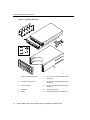
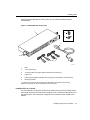
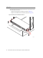
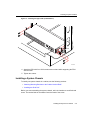
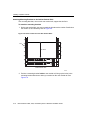
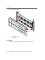
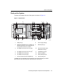
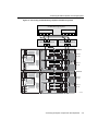
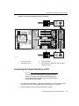
Stratus® ftServer® 2600, 4500, and 6300 Systems:
Hardware Installation Guide
Stratus Technologies
R640-02
Notice
The information contained in this document is subject to change without notice.
UNLESS EXPRESSLY SET FORTH IN A WRITTEN AGREEMENT SIGNED BY AN AUTHORIZED
REPRESENTATIVE OF STRATUS TECHNOLOGIES, STRATUS MAKES NO WARRANTY OR REPRESENTATION
OF ANY KIND WITH RESPECT TO THE INFORMATION CONTAINED HEREIN, INCLUDING WARRANTY OF
MERCHANTABILITY AND FITNESS FOR A PURPOSE. Stratus Technologies assumes no responsibility or obligation
of any kind for any errors contained herein or in connection with the furnishing, performance, or use of this document.
Software described in Stratus documents (a) is the property of Stratus Technologies Bermuda, Ltd. or the third party,
(b) is furnished only under license, and (c) may be copied or used only as expressly permitted under the terms of the
license.
Stratus documentation describes all supported features of the user interfaces and the application programming
interfaces (API) developed by Stratus. Any undocumented features of these interfaces are intended solely for use by
Stratus personnel and are subject to change without warning.
This document is protected by copyright. All rights are reserved. No part of this document may be copied, reproduced,
or translated, either mechanically or electronically, without the prior written consent of Stratus Technologies.
Stratus, the Stratus logo, ftServer, and the ftServer logo are registered trademarks of Stratus Technologies Bermuda,
Ltd.
The Stratus Technologies logo, the Stratus 24 x 7 logo, ActiveService, ftScalable, and Active Upgrade are trademarks
of Stratus Technologies Bermuda, Ltd.
The registered trademark Linux is used pursuant to a sublicense from the Linux Mark Institute, the exclusive licensee
of Linus Torvalds, owner of the mark on a world-wide basis. FLEXlm is a registered trademark of Macrovision
Corporation.
VMware, vSphere, ESX, and VMotion are registered trademarks or trademarks of VMware, Inc. in the United States
and/or other jurisdictions.
All other trademarks are the property of their respective owners.
Manual Name: Stratus ftServer 2600, 4500, and 6300 Systems: Hardware Installation Guide
Part Number: R640
Revision Number: 02
Software Release Number: ftServer System Software for the Windows Operating System, Release Number: 6.0.0
ftServer System Software for the Linux Operating System, Release Number: 7.0.4
ftServer System Software for VMware vSphere, Release Number: 3.0.0
Publication Date: February 2010
Stratus Technologies, Inc.
111 Powdermill Road
Maynard, Massachusetts 01754-3409
© 2010 Stratus Technologies Bermuda, Ltd. All rights reserved.
Contents
Preface
vii
1. Unpacking Your System
Checking the System Components
Inspecting the System
Verifying the System Serial Number
Safety Notices
Safety Considerations
1-1
1-1
1-3
1-4
1-4
1-10
2. Installing the System in a Cabinet
Numbering the Vertical Rails
Installing PDUs
Installing a System Chassis
Installing the System Enclosures
Next Steps
2-1
2-2
2-4
2-9
2-19
2-24
3. Connecting the System Components and Peripherals
PCI Adapters
Ports on the System
Managing Cables
Connecting a Monitor, Mouse, and Keyboard
Connecting the ftServer System to a Storage System
Connecting ftServer Systems to EMC Storage Systems
Connecting the Ethernet Ports to Networks
Connecting the VTM Ports to a Network
Connecting the Modem to a Phone Line
Connecting Tape Drives (Windows and Linux Systems)
Next Steps
3-1
3-1
3-3
3-4
3-4
3-5
3-6
3-10
3-11
3-11
3-12
3-13
Contents
iii
Contents
4. Connecting the System to Electrical Power
System Power Overview
Connecting the System to AC Power (Mains)
Connecting the System Directly to a UPS
Connecting Systems to Power Through PDUs
Next Steps
4-1
4-1
4-2
4-3
4-5
4-9
Appendix A. Hardware Replacement and System Support
A-1
Index
iv
Stratus ftServer 2600, 4500, and 6300 Systems: Hardware Installation Guide
Index-1
Figures
Figure 1-1.
Figure 2-1.
Figure 2-2.
Figure 2-3.
Figure 2-4.
Figure 2-5.
Figure 2-6.
Figure 2-7.
Figure 2-8.
Figure 2-9.
Figure 2-10.
Figure 2-11.
Figure 2-12.
Figure 2-13.
Figure 2-14.
Figure 2-15.
Figure 2-16.
Figure 2-17.
Figure 2-18.
Figure 2-19.
Figure 2-20.
Figure 2-21.
Figure 3-1.
Figure 3-2.
Figure 3-3.
Figure 3-4.
Figure 3-5.
Figure 3-6.
Figure 4-1.
Figure 4-2.
Figure 4-3.
Figure 4-4.
v
System Components
EIA Vertical Rail Hole Pattern
Numbering the Middle Hole of 6U
AAP87600F PDU Components
Cage Nut Locations: PDU
Inserting Cage Nuts
Installing the Lower PDU (at U Number 1)
Installing the Upper PDU (at U Number 2)
Screw Locations on the Rear Vertical Rails
Attaching the Mounting Brackets and Inserting Guide
Screws (Rear View)
Removing the Front Panel from the Shelf Unit
Removing the System Backplane
Cage Nut Locations on Front Vertical Rails
Mounting the Shelf Unit on the Mounting Brackets
Securing the Shelf Unit to the Front Rails
Securing the Shelf Unit to the Mounting Brackets
Reinstalling the System Backplane Assembly
Replacing the Front Panel in the Shelf Unit
Removing the Metal Plate from the Backplane
Installing the Modem Assembly
Installing the CPU-I/O Enclosures in a Cabinet
Installing the Bezel
System Ports
Connecting Symmetrix Storage Systems and ftServer
Systems
Connecting CLARiiON Storage Systems and ftServer
Systems
Connecting the Cable to the Modem
SFF-8470 Connector
Connecting a Tape Drive to an ftServer System
Connecting a System Directly to AC Power
Connecting a System to a UPS
Connecting the Systems Directly to PDUs
Connecting the Systems to PDUs and a UPS
Stratus ftServer 2600, 4500, and 6300 Systems: Hardware Installation Guide
1-2
2-2
2-4
2-5
2-6
2-7
2-8
2-9
2-10
2-11
2-12
2-13
2-14
2-15
2-16
2-17
2-18
2-19
2-20
2-21
2-22
2-24
3-3
3-7
3-9
3-12
3-13
3-13
4-3
4-5
4-7
4-8
Figures
vi
Stratus ftServer 2600, 4500, and 6300 Systems: Hardware Installation Guide
Preface
The Stratus ftServer 2600, 4500, and 6300 Systems: Hardware Installation Guide
describes how to:
• Unpack the system
• Install the system in a cabinet
• Connect the system components and peripherals
• Connect the system to electrical power
Revision Information
This manual is a revision. It includes information about ftServer System Software for
VMware® vSphere™
, Release 3.0.0.
NOTE
ftSSS for VMware vSphere is not available on
ftServer 2600 systems.
Notation Conventions
This document uses the notation conventions described in this section.
Warnings, Cautions, and Notes
Warnings, cautions, and notes provide special information and have the following
meanings:
!
WARNING
A warning indicates a situation where failure to take
or avoid a specified action could cause bodily harm
or loss of life.
Preface
vii
Preface
!
CAUTION
A caution indicates a situation where failure to take or
avoid a specified action could damage a hardware device,
program, system, or data.
NOTE
A note provides important information about the operation
of an ftServer system.
Typographical Conventions
The following typographical conventions are used in this document:
• The bold font emphasizes words in text or indicates text that you type, the name of
a screen object, or the name of a programming element. For example:
Before handling or replacing system components, make sure that you are
properly grounded by using a grounded wrist strap.
In the System Properties dialog box, click the Hardware tab.
Call the RegisterDeviceNotification function.
• The italic font introduces new terms and, in Windows® operating system contexts
indicates programming and command-line arguments that the user supplies. For
example:
Many hardware components are customer-replaceable units (CRUs), which
can be replaced on-site by system administrators with minimal training or tools.
copy filename1 filename2
Pass a pointer for the NotificationFilter parameter
• The monospace font indicates sample program code and output, including
message text. For example:
#include <iostream.h>
The operation completed successfully.
viii
Stratus ftServer 2600, 4500, and 6300 Systems: Hardware Installation Guide
Preface
• The monospace font also represents text that would appear on your display
screen. The monospace bold font represents text you must type in examples that
contain both user input and system output. The monospace italic font represents
terms in command lines that are to be replaced by literal values. For example:
To display the state of a CPU enclosure, type a command in the following
format:
/opt/ft/bin/ftsmaint ls n
If you type /opt/ft/bin/ftsmaint ls 0 at the prompt, the following
output appears:
H/W Path : 0
Description : CPU Node Assembly
.
.
.
• The percent sign (%), dollar sign ($), and number sign (#) are default prompt signs
that have a specific meaning at a Linux or VMware ESX™ command prompt.
Although a prompt is sometimes shown at the beginning of a command line as it
would appear on the screen, you do not type it.
– % or $ indicates you are logged in to a standard user account and are subject
to certain access limitations. The prompt displayed on the screen depends on
your shell environment, for example, csh (%) or bash ($).
– # indicates you are logged in to the system administrator account and have
superuser access. Users of this account are referred to as root. The # prompt
sign used in an example indicates the command can be issued only by root.
Getting Help
If you have a technical question about ftServer system hardware or software, try these
online resources first:
• Online documentation at the StrataDOC Web site. Stratus provides
complimentary access to StrataDOC, an online-documentation service that
enables you to view, search, download, and print customer documentation. You
can access StrataDOC at the following Web site:
http://stratadoc.stratus.com
Preface
ix
Preface
A copy of StrataDOC on supported media for your system is included with this
release. To order additional copies of the StrataDOC media or to obtain copies of
printed manuals, do one of the following:
– If you are in North America, call the Stratus Customer Assistance
Center (CAC) at (800) 221-6588 or (800) 828-8513, 24 hours a day, 7 days a
week.
– If you are located outside North America, contact your nearest Stratus sales
office, CAC office, or distributor; for CAC phone numbers outside the U.S., see:
http://www.stratus.com/support/cac/
• Online support from Stratus Customer Service. You can find the latest technical
information about an ftServer system through online product support at the Stratus
Technical Support Web site:
http://www.stratus.com/support/
• Online product support for Microsoft® products. Your primary source for
support is the computer manufacturer who provided your software, or an
authorized Microsoft Support Provider. You can also find the latest technical
information about Microsoft Windows® and other Microsoft products through online
product support at the Microsoft Help and Support Web site:
http://support.microsoft.com/
• Online product support for Red Hat® Linux products. Your primary source for
support is the manufacturer who provided your software, or Red Hat Global
Support Services. You can also find the latest technical information about Red Hat
Enterprise and Standard Linux through online product support at the Red Hat
Support Web site:
http://www.redhat.com/apps/support/
• Online product support for VMware vSphere products. You can find the latest
technical information about VMware vSphere through online product support at the
VMware Support Web site:
http://www.vmware.com/support/
If you are unable to resolve your questions with the help available at these online sites,
and the ftServer system is covered by a service agreement, please contact the Stratus
Customer Assistance Center (CAC) or your authorized Stratus service representative.
For information about how to contact the CAC, see the following Web site:
http://www.stratus.com/support/cac/
x
Stratus ftServer 2600, 4500, and 6300 Systems: Hardware Installation Guide
Preface
Commenting on the Documentation
To provide corrections and suggestions on the documentation, send your comments in
one of the following ways:
• By clicking the site feedback link at the bottom of a Help topic. Information to
identify the topic is supplied in the StrataDOC Web Site Feedback form.
• By email to [email protected]. If it is possible, please include specific
information about the documentation on which you are commenting:
– For a printed document or a document in PDF format, include the title and part
number from the Notice page and the page numbers.
– For online documentation, include the Help subject and topic title.
This information will assist Stratus Information Development in making any needed
changes to the ftServer system documentation. Your assistance is most appreciated.
Regulatory Notice
All regulatory notices are provided in the site planning guide for your system.
Preface
xi
Preface
xii
Stratus ftServer 2600, 4500, and 6300 Systems: Hardware Installation Guide
Chapter 1
Unpacking Your System
1-
When you receive your system, unpack it as described in the Read Me First booklet
that accompanies the system.
After you unpack the system, do the following:
• Make sure you have the components you require and have ordered.
• Inspect the system to make sure nothing was damaged during shipment.
• Verify that the system serial number on the system label and on the packing list
match.
• Make sure you understand safety considerations.
Checking the System Components
Refer to the packing list on the box and make sure you have all of the ordered
components:
• The components shown in Figure 1-1 and the accessories box
• In the accessories box, components that typically include the following items
(though the exact contents vary according to the system ordered):
– Software DVDs – both operating system and ftServer System Software
– Stratus hard copy manuals
– Power cords
– Stratus bezel
– Keyboard and mouse (if ordered)
– Supplier data sheets and driver disks that might accompany purchased options
(i.e., disk drives, PCI cards, etc.)
– Bag of screws, cage nuts, and washers, and the rack mount kit for mounting
the system in a cabinet
– ESD wrist strap
Unpacking Your System
1-1
Checking the System Components
Figure 1-1. System Components
1
2
3
6
9
7
10
8
4
5
dco023a
1-2
1
Rear mounting brackets (2)
6
10-32 x 1/2 in. flat-head Phillips-head
screws (8)
2
CPU-I/O enclosures (2)
7
10-32 x 5/8 in. flat-head Phillips-head
screws (4)
3
Power cords (2)
8
10-32 x 1/2 panhead screws with cup
washer (4)
4
Shelf unit
9
10-32 cage nuts (8)
5
Bezel
10
10/32 countersunk lock washers (12)
Stratus ftServer 2600, 4500, and 6300 Systems: Hardware Installation Guide
Inspecting the System
NOTE
Each ftServer 2600, 4500, and 6300 system ships with
two AW-B50107-07 power cords as standard equipment.
If these are not appropriate for use in your country or
configuration, refer to the power cord tables in the Stratus
ftServer 2600, 4500, and 6300 Systems: Site Planning
Guide (R638) to select the power cord that meets your
configuration and country’s power connection
requirements.
• The following components, if ordered:
– ftScalable™ Storage systems
– Pairs of U539F Single-Port Optical Fibre Channel PCI Adapters or, for VMware
ESX systems, U777F Single-Port Optical Fibre Channel PCI Adapters, for
connecting the server to ftScalable Storage systems or EMC® storage systems
One adapter from each pair is installed in each CPU- I ⁄ O enclosure.
– Pairs of network adapters, one of each pair installed in each
CPU- I ⁄ O enclosure. Supported models are U104 Dual-Port Fiber Gigabit
Ethernet PCI-Express Adapters, U105 Dual-Port 10/100/1000 Base-T
Ethernet PCI-Express Adapters, and U108 Single-Port Fiber 10-Gigabit
Ethernet PCI-Express Adapters. (Contact your account team for information on
the availability (on Linux systems only) of the U108 PCIe adapter.)
– A U106 Eight-Port SAS PCI-Express Adapter, installed in a single
CPU- I ⁄ O enclosure
– Rack-mounted flat-panel LCD monitor unit
– PDUs
Each CPU- I ⁄ O enclosure contains a CPU element and an I/O element joined to the
same board. The CPU elements and I/O elements are numbered as follows:
• Upper enclosure: CPU element - 0 and I/O element - 10
• Lower enclosure: CPU element - 1 and I/O element - 11
Inspecting the System
Inspect all equipment for damage. Verify that the equipment has no dents, scratches,
or scrapes. If you notice damage, contact the Stratus Customer Assistance
Center (CAC) or your authorized Stratus service representative.
Unpacking Your System
1-3
Verifying the System Serial Number
Verifying the System Serial Number
Make sure that the serial numbers on the system and on the packing list match.
1. Find the label that contains the serial number and site ID affixed to the bottom rear
of the shelf unit.
2. Compare the serial number on the label with the serial number on the packing list.
If the serial numbers do not match, contact the CAC or your authorized Stratus service
representative before installing the system.
Safety Notices
!
WARNING
Risk of explosion if battery is replaced by an incorrect
type. Dispose of used batteries according to the
instructions provided with the battery.
!
WARNING
The system uses two power cords to provide
redundant sources of power. To fully remove power
from a system, disconnect both power cords. To
reduce the risk that electrical shock could injure a
person or damage the system, exercise caution when
working in the unit even when only one power cord is
connected.
!
WARNING
To prevent a cabinet from tipping over and injuring a
person or damaging the system, start installing
systems from the bottom of the cabinet upward.
!
WARNING
If you replace the modem cable supplied by Stratus,
use a cable with a gauge of at least a UL-approved
26 AWG to prevent fire.
1-4
Stratus ftServer 2600, 4500, and 6300 Systems: Hardware Installation Guide
Safety Notices
!
WARNING
To avoid fire, electric shock, and equipment
breakdown, prevent water or foreign objects from
getting into the equipment. Do not let water or foreign
objects, such as pins or paper clips, enter the
equipment.
!
WARNING
To prevent fire or current leakage, do not plug the
power cord into a nonconforming outlet. Use a power
outlet with appropriate voltage and power type, as
specified in this guide.
!
WARNING
Do not install the equipment where you may need an
extension cord. Use of an extension cord that does
not meet the power specifications introduces a risk of
overheating that could lead to a fire.
!
WARNING
Disconnect the power cords from the server or power
source before you install or relocate the equipment.
All voltage is removed only when the power cords are
disconnected.
!
WARNING
Do not install or store the equipment in an unsuitable
place. Install or store the equipment in a place that
meets the requirements specified in this guide. Avoid
the following conditions to avoid the risk of fire:
• Dust
• High humidity, such as a place near a boiler
• Direct sunlight
• Instability, such as places not stabilized against
earthquakes
Unpacking Your System
1-5
Safety Notices
!
WARNING
Do not use or store this product in a corrosive
environment.
Avoid using or storing this product in an environment
which may contain corrosive gases. Such gases
include, but are not limited to, sulfur dioxide,
hydrogen sulfide, nitrogen dioxide, chlorine,
ammonia, or ozone.
Avoid installing this product in a dusty environment
or one that may contain corrosive materials such as
sodium chloride or sulfur.
Avoid installing this product in an environment which
may contain excessive metal flakes or conductive
particles in the air.
Such environments may cause corrosion or short
circuits within this product, resulting in not only
damage to this product, but also fire.
If there are any concerns regarding the environment
at the planned site of installation or storage, please
contact the CAC or your authorized Stratus service
representative.
!
WARNING
When installing a system or CRU, always connect the
power cord first, before adding communications
cables. The power cord contains the protective earth
connection; it should be connected first and
disconnected last, to maintain a grounded chassis.
Before attempting to remove a CRU from the system
chassis, make sure to power off the CRU, disconnect
communications cables, and then disconnect the
power cord.
Never connect a power cord to a CRU when it is not
located within the system chassis.
1-6
Stratus ftServer 2600, 4500, and 6300 Systems: Hardware Installation Guide
Safety Notices
!
WARNING
Do not disassemble, repair, or alter the server, except
as described in the Stratus ftServer 2600, 4500, and
6300 Systems: Operation and Maintenance
Guide (R639). There is a risk of an electric shock or
fire as well as equipment malfunction if you do not
observe the instructions in the Stratus ftServer 2600,
4500, and 6300 Systems: Operation and Maintenance
Guide (R639).
!
WARNING
Do not place any object on top of the server. The
object may fall off and cause injuries, damage to
hardware, or a fire.
!
WARNING
Do not leave the DVD tray ejected. Dust may enter the
equipment and cause it to malfunction. The ejected
tray may also become a cause of injuries.
!
WARNING
!
WARNING
Unpacking Your System
1-7
Safety Notices
1-8
!
WARNING
!
WARNING
!
WARNING
!
WARNING
!
WARNING
!
WARNING
Stratus ftServer 2600, 4500, and 6300 Systems: Hardware Installation Guide
Safety Notices
!
WARNING
|
!
WARNING
!
WARNING
!
WARNING
Unpacking Your System
1-9
Safety Considerations
!
WARNING
!
WARNING
Safety Considerations
Before installing the system, take the following important precautions:
• Observe all applicable industry safety standards. See the “Safety Notices” on
page 1-4.
• Provide the necessary space and light to safely perform the installation.
• Do not wear conducting objects, such as rings, bracelets, and keys.
1-10
Stratus ftServer 2600, 4500, and 6300 Systems: Hardware Installation Guide
Chapter 2
Installing the System in a Cabinet
2-
Before installing the system components, make sure that:
• Your cabinet meets the system requirements.
• The site has been properly prepared.
The requirements for the cabinet and for site planning are described in the Stratus
ftServer 2600, 4500, and 6300 Systems: Site Planning Guide (R638), which is
available on the StrataDOC disk that is shipped with your system and on the
StrataDOC Web site at http://stratadoc.stratus.com. Many of the basic procedures
covered in this document are also demonstrated in an Adobe® Flash™ movie at the
following Web site:
http://stratadoc.stratus.com/flash/fusionh/chassis_install_6300.html
To install the system components in a cabinet, see the following topics and refer to
Figure 1-1, which identifies the system components:
• “Numbering the Vertical Rails” on page 2-2
• “Installing PDUs” on page 2-4
• “Installing a System Chassis” on page 2-9
• “Installing the System Enclosures” on page 2-19
• “Next Steps” on page 2-24
Tools required for installing a cabinet system:
• A #2 Phillips-head screwdriver
• A flat-head screwdriver and a cage-nut insertion/extraction tool
!
WARNING
Two people are required to install a cabinet.
Installing the System in a Cabinet
2-1
Numbering the Vertical Rails
Numbering the Vertical Rails
If your rack is not already numbered, use a marker or pencil to number the middle hole
of at least the following:
• The 4U in which to install each system
• The 2U in which to install each storage enclosure, if ordered
• The 1U in which to install a rack-mountable LCD monitor unit, if ordered
NOTE
The cabinet rails, system, and various components are
measured in Electronic Industries Alliance (EIA) rack
units (U). Every three holes on the EIA square-hole
pattern on the vertical rail equals one U (1.75 in.,
4.45 cm). The holes on EIA rails are located in a repeating
pattern of 1/2 in. (1.27 cm), 5/8 in. (1.59 cm), 5/8 in.
(1.59 cm), as shown in Figure 2-1. The middle hole of
each U has equal spacing between it and the holes
adjacent to it. In some cabinets, numbers on the vertical
rails identify the middle hole of each U.
Figure 2-1. EIA Vertical Rail Hole Pattern
1U
5/8 in.
(1.59 cm)
1U
5/8 in.
(1.59 cm)
1/2 in.
(1.27 cm)
cnut005
2-2
Stratus ftServer 2600, 4500, and 6300 Systems: Hardware Installation Guide
Numbering the Vertical Rails
To number the vertical rails in a cabinet
1. On each of the front and rear rails, number the two U where you will install the
PDUs. Mark the number 1 next to the middle hole of the first U and the number 2
next to the middle hole of the second U, as shown in Figure 2-2.
2. On each of the front and rear rails, number the middle hole of the four U where you
will install the system. Mark the number 3 next to the middle hole of the third U, the
number 4 next to the middle hole of the fourth U, the number 5 next to the middle
hole of the fifth U, and the number 6 next to the middle hole of the sixth U, as shown
in Figure 2-2
3. If you are installing additional systems in the same cabinet, continue numbering the
middle hole of another 4U for each system.
4. If you are installing a rack-mountable LCD monitor unit, number 1U for each LCD
monitor unit.
5. If you are installing ftScalable Storage systems, number 2U for each storage
system.
To ensure that the components will be level when you install them, mark the same
holes on the rear rails that you marked on the front vertical rails.
Installing the System in a Cabinet
2-3
Installing PDUs
Figure 2-2. Numbering the Middle Hole of 6U
6
6
5
5
4
4
3
3
2
2
1
1
cnut006
Installing PDUs
To install PDUs, see:
• “PDU Components”
• “Installing PDUs in a Cabinet”
To connect the PDUs to AC power, see “Connecting Systems to Power Through PDUs”
on page 4-5.
PDU Components
The PDUs are ordered and shipped in pairs. Each PDU is shipped with mounting
brackets attached.
The model AA-P87600 PDU (Figure 2-3) supports ftServer 2600, 4500, and 6300
systems. Verify that you have the components shown for your PDU, and inspect the
components to ensure that they are not damaged. If you notice damage, contact the
2-4
Stratus ftServer 2600, 4500, and 6300 Systems: Hardware Installation Guide
Installing PDUs
Stratus Customer Assistance Center (CAC) or your authorized Stratus service
representative.
Figure 2-3. AAP87600F PDU Components
1
2
3
4
6
5
pdu001a
1
PDU
2
10-32 cage nuts (4)
3
10-32 pan-head screws with captive external tooth washers (4)
4
Power cord
5
Power (jumper) cables (one black and one gray) from the system’s accessories box
6
Mounting brackets†
† To ensure a proper ground connection from the PDU to the cabinet, the mounting
brackets must remain on the non-painted surface of the PDU.
Installing PDUs in a Cabinet
You can install one or two pairs of PDUs in a cabinet, for a total of four PDUs. Install
the first pair of PDUs in the bottom two contiguous one-U locations of the cabinet, and
the second pair in two convenient, contiguous one-U locations in the middle of the
cabinet.
Installing the System in a Cabinet
2-5
Installing PDUs
For each pair of PDUs, the PDU in the top U provides A-side power. That is, the PDU
in the top location powers one CPU- I ⁄ O enclosure and one side of an external storage
enclosure, and is the only source of power to tape drives and LCD monitor units. The
PDU in the bottom location provides B-side power. That is, it provides power to the
other CPU- I ⁄ O enclosure and to the other side of an external storage enclosure.
Removable fasteners attach two reversible mounting brackets to the body of the PDU.
To install a PDU
1. For each PDU, insert four cage nuts in the rear vertical cabinet rails. Insert two
cage nuts in each rear rail, in the top and bottom holes of U positions 1 and 2. The
locations in which to install the cage nuts for two PDUs are indicated in Figure 2-4.
Figure 2-4. Cage Nut Locations: PDU
2
1
cnut002a
NOTE
To insert cage nuts, position them so that the tabs are on
the top and bottom (Figure 2-5). Then insert the cage nut
so that its top overlaps the vertical rails, and use a
cage-nut insertion tool or your fingers to pull the rest of the
cage nut through so that the bottom tab overlaps the
vertical rail.
2-6
Stratus ftServer 2600, 4500, and 6300 Systems: Hardware Installation Guide
Installing PDUs
Figure 2-5. Inserting Cage Nuts
dco022
2. Hold the PDU at the back of the cabinet, so that the power outlets and controls face
you, and the blank side of the PDU faces the inside of the cabinet, as shown in
Figure 2-6.
Installing the System in a Cabinet
2-7
Installing PDUs
3. Align the screw holes on the mounting brackets with the top and bottom holes of
the U with cage nuts, as follows:
• Align the first PDU with the U numbered 1 (as shown in Figure 2-6).
• Align the second PDU with the U numbered 2 (as shown in Figure 2-7).
Figure 2-6. Installing the Lower PDU (at U Number 1)
TV L-N
S
PW L-L
R
U1
GR
D
dco024
2-8
Stratus ftServer 2600, 4500, and 6300 Systems: Hardware Installation Guide
Installing a System Chassis
Figure 2-7. Installing the Upper PDU (at U Number 2)
TV L-N
S
PW L-L
R
U2
GR
D
dco024a
4. Attach the PDU with four 10-32 screws with one hand while supporting the PDU
with the other.
5. Tighten the screws.
Installing a System Chassis
To install your system chassis in a cabinet, see the following sections:
• “Attaching Mounting Brackets to the Cabinet Vertical Rails”
• “Installing the Shelf Unit”
Before you start assembling the system chassis, add a lock washer to each flat-head
screw. The toothed side of the washer faces the head of the screw.
Installing the System in a Cabinet
2-9
Installing a System Chassis
Attaching Mounting Brackets to the Cabinet Vertical Rails
Two mounting brackets, one on each rear vertical rail, support the shelf unit.
To attach the mounting brackets
1. On the rear vertical rails, use a pen to mark the hole above the number 5 and below
the number 4, as indicated by dots in Figure 2-8.
Figure 2-8. Screw Locations on the Rear Vertical Rails
Dot
7
7
6
6
1U
5
5
1U
4
4
1U
3
3
1U
2
2
1
1
4U Total
Cabinet Rear View
dco057
2. Position a mounting bracket inside a rear vertical rail, lining up the holes in the
mounting bracket with the two holes you marked on the rear vertical rail. See
Figure 2-9.
2-10
Stratus ftServer 2600, 4500, and 6300 Systems: Hardware Installation Guide
Installing a System Chassis
3. Insert and tighten two 10-32 x 1/2-in. pan-head crest-cup screws (number 1 in
Figure 2-9) through the marked holes in the rear vertical rails and into the holes in
the mounting bracket.
4. Repeat steps 2 and 3 for the second mounting bracket.
Figure 2-9. Attaching the Mounting Brackets and Inserting Guide Screws (Rear View)
4
3
2
6
5
4
5
1
3
dco056
1
10-32 x 1/2 pan-head crest-cup screw
4
Third hole from rear
2
First hole from rear
5
3
Second hole from rear
Guide screw (to be inserted in one of
three indicated holes)
5. Measure the distance between the front and rear vertical rails in the cabinet and
install one guide screw and washer at the top of each mounting bracket, as follows:
• If the rail depth is less than 27 in. (68.58 cm), install a flat-head screw with
countersunk lock washer in the hole closest to the rear of the cabinet
(number 2 in Figure 2-9).
• If the rail depth is 27 in. (68.58 cm), install a flat-head screw with countersunk
lock washer in the second hole from the rear (number 3).
• If the rail depth is greater than 27 in. (68.58 cm), install a flat-head screw with
countersunk lock washer in the third hole from the cabinet rear (number 4).
Installing the System in a Cabinet
2-11
Installing a System Chassis
Installing the Shelf Unit
The shelf unit comes with a front panel and the system backplane installed. Before
installing the shelf unit in the cabinet, you must remove the front panel and system
backplane from the shelf unit in order to be able to gain access to the screw holes at
the rear of the shelf unit.
1. To remove the front panel (number 1 in Figure 2-10):
a. Loosen the captive thumbscrew (number 2) at the bottom of the front panel.
b. Gripping the bracket (number 3) on the right side of the panel, pull the front
panel straight out of its slot and out of the shelf unit.
Figure 2-10. Removing the Front Panel from the Shelf Unit
3
1
2
dco028b
1
Front panel
2
Captive thumbscrew
3
Bracket
2. To remove the system backplane (number 1 in Figure 2-11), loosen the two
thumbscrews (number 3) on the right side of the system backplane assembly.
2-12
Stratus ftServer 2600, 4500, and 6300 Systems: Hardware Installation Guide
Installing a System Chassis
Figure 2-11. Removing the System Backplane
1
4
2
3
dco016a
1
System backplane assembly
3
System backplane thumbscrews
2
Guide pins
4
Retaining tab
3. Slide the system backplane assembly to the right, out from beneath the retaining
tab (number 4), and pull the assembly out of the shelf unit.
4. At the front of the cabinet, insert two cage nuts into each vertical rail in the locations
shown in Figure 2-12.
Installing the System in a Cabinet
2-13
Installing a System Chassis
Figure 2-12. Cage Nut Locations on Front Vertical Rails
NOTE
To insert cage nuts, position the cage nuts so that the tabs
are on the top and bottom (Figure 2-5). Then insert the
cage nut so that the top tab on the cage nut overlaps the
vertical rails. Use a cage-nut insertion tool or your fingers
to pull the rest of the cage nut through so that the bottom
tab overlaps the vertical rail.
!
WARNING
To avoid personal injury or damage to the shelf unit,
two persons are required to insert the shelf unit into
the cabinet and onto the mounting brackets.
5. With one person at the front of the cabinet and one person at the rear of the
cabinet, insert the shelf unit into the cabinet and onto the mounting brackets.
a. At the front of the cabinet, slide the shelf unit into the cabinet.
b. At the rear of the cabinet, flex the right (from the rear) mounting bracket
towards the side of the cabinet, and guide the shelf unit so that the guide slot
(number 1 in Figure 2-13) at the top right of the shelf unit aligns with the guide
screw (number 2) on your right.
2-14
Stratus ftServer 2600, 4500, and 6300 Systems: Hardware Installation Guide
Installing a System Chassis
c. Perform the same action on the other side of the cabinet.
Figure 2-13. Mounting the Shelf Unit on the Mounting Brackets
1
2
dco025
1
Guide slots (2)
2
Guide screws (2)
6. At the front of the cabinet, slide the shelf unit all the way in.
7. In the locations shown in Figure 2-14, secure the shelf unit to the vertical rails by
inserting and tightening two 10-32 x 5/8 flat-head screws (number 1) with
countersunk lock washers (number 2) into each mounting flange on the shelf unit
and into countersunk lock washers.
Installing the System in a Cabinet
2-15
Installing a System Chassis
Figure 2-14. Securing the Shelf Unit to the Front Rails
2
1
1
10-32 x 5/8 flat-head screws (4)
2
Countersunk lock washers (4)
8. Tighten the two guide screws.
9. Secure each side of the shelf unit to a rear mounting bracket (number 1 in
Figure 2-15) with three 10-32 x 1/2-in. flat-head screws (number 2) with
countersunk lock washers on each side, as shown in Figure 2-15.
Tighten the six screws.
2-16
Stratus ftServer 2600, 4500, and 6300 Systems: Hardware Installation Guide
Installing a System Chassis
Figure 2-15. Securing the Shelf Unit to the Mounting Brackets
2
1
dco027
1
Mounting brackets (2)
2
10-32 x 1/2 in. flat-head screws with countersunk lock washers (6)
10. Reinstall the system backplane assembly as follows:
a. Position the system backplane assembly as shown in Figure 2-16. Note the
position of the guide pins (number 2).
Installing the System in a Cabinet
2-17
Installing a System Chassis
Figure 2-16. Reinstalling the System Backplane Assembly
1
4
2
3
dco016a
1
System backplane assembly
3
System backplane thumbscrews
2
Guide pins
4
Retaining tab
b. Insert the system backplane assembly into the shelf unit, then slide the
backplane to the left and beneath the retaining tab (number 4).
c. The thumbscrews (number 3) on the assembly should line up with the screw
holes on the rear of the shelf unit.
d. Tighten the two thumbscrews on the system backplane assembly to fasten it
to the shelf unit.
11. Reinstall the front panel into the shelf unit as follows:
a. Align the front panel with the slot in the front right side of the shelf unit and push
it straight into the slot, as shown in Figure 2-17.
2-18
Stratus ftServer 2600, 4500, and 6300 Systems: Hardware Installation Guide
Installing the System Enclosures
Figure 2-17. Replacing the Front Panel in the Shelf Unit
3
1
2
dco028b
1
Front panel
2
Captive thumbscrew
3
Bracket
b. Tighten the captive thumbscrew (number 2 in Figure 2-10) at the bottom of the
panel.
Installing the System Enclosures
After you have installed the shelf unit (and reinstalled the system backplane assembly
and the front panel), you must install the modem (if one was ordered), the CPU-I/O
enclosures, and the bezel.
1. Install the modem assembly, if one was ordered.
a. At the rear of the system, remove the metal plate (number 1 in Figure 2-18)
from the system backplane by removing the two Phillips head screws.
Installing the System in a Cabinet
2-19
Installing the System Enclosures
Figure 2-18. Removing the Metal Plate from the Backplane
1
dco017
1
Metal plate
b. Insert the modem assembly (number 1 in Figure 2-19) into its slot on the
backplane.
c. Tighten the thumbscrews (number 2).
2-20
Stratus ftServer 2600, 4500, and 6300 Systems: Hardware Installation Guide
Installing the System Enclosures
Figure 2-19. Installing the Modem Assembly
1
2
2
dco017a
1
Modem assembly
2
Thumbscrews (2)
2. Install the CPU- I ⁄ O enclosures.
a. Place each CPU- I ⁄ O enclosure on a flat surface and pull the two ejector levers
(number 1 and shown boxed in Figure 2-20) down.
NOTE
If your shipment contains an operating system DVD, the
operating system and the ftServer System Software were
installed at the factory. In this case, install the
CPU- I ⁄ O enclosure that contains the boot disk (labeled
boot) in the top CPU-I/O slot.
Installing the System in a Cabinet
2-21
Installing the System Enclosures
b. With the ejector levers in the open (down) position, slide each
CPU- I ⁄ O enclosure into the shelf unit.
!
WARNING
Lifting a CPU-I/O enclosure requires two persons.
Figure 2-20. Installing the CPU-I/O Enclosures in a Cabinet
1
3
2
dco029
2-22
1
Ejector lever in open position
2
Ejector lever engaged with positioning pin
3
Thumbscrew
Stratus ftServer 2600, 4500, and 6300 Systems: Hardware Installation Guide
Installing the System Enclosures
c. With the bottom of the ejector levers engaged with the positioning pin
(number 2), push the ejector levers up into the closed position and tighten the
thumbscrews (number 3) to install the system securely into the rack.
!
CAUTION
Be sure to press the ejector levers flush against the front
of the system before tightening the thumbscrews;
otherwise, the thumbscrew threads will be stripped.
3. Attach the bezel.
a. Facing the front of the system, hold the bezel so that the LED light pipes inside
the bezel (number 1 Figure 2-21) are on the right. Align the light pipes with the
four front-panel system LEDs.
!
CAUTION
The bezel light pipes extend about 0.25 in. (0.635 cm) out
from the inside of the bezel. Be careful not to bend or hit
the light pipes when installing the bezel.
b. Holding the bezel in front of the mounting rails, align its ball-stud holes with the
ball studs (number 2 in Figure 2-21) on the sides of the system (two on the left
side and two on the right).
Figure 2-21 shows the front of the system, with the bezel aligned with the cabinet
for installation.
Installing the System in a Cabinet
2-23
Next Steps
Figure 2-21. Installing the Bezel
1
2
dco003
1
Light pipes (an array of 4)
2
Ball studs (4)
Next Steps
Connect the system components and peripherals, as described in Chapter 3.
2-24
Stratus ftServer 2600, 4500, and 6300 Systems: Hardware Installation Guide
Chapter 3
Connecting the System Components
and Peripherals
3-
To connect your system components and peripherals, see:
• “PCI Adapters” on page 3-1
• “Ports on the System” on page 3-3
• “Managing Cables” on page 3-4
• “Connecting a Monitor, Mouse, and Keyboard” on page 3-4
• “Connecting the ftServer System to a Storage System” on page 3-5
• “Connecting the Ethernet Ports to Networks” on page 3-10
• “Connecting the VTM Ports to a Network” on page 3-11
• “Connecting the Modem to a Phone Line” on page 3-11
• “Connecting Tape Drives (Windows and Linux Systems)” on page 3-12
• “Next Steps” on page 3-13
No tools are required for these tasks.
PCI Adapters
Each ftServer 2600 CPU-I/O enclosure supports two low-profile adapter slots. Each
ftServer 4500 and ftServer 6300 CPU-I/O enclosure contains two low-profile PCI
adapter slots and optional PCIe or PCI-X riser assemblies. The low-profile PCI adapter
slots appear as slots 1 and 2 (numbers 5 and 6, respectively) in Figure 3-1. The riser
assembly can provide two additional PCI adapter slots that can accept full-height
adapters (PCI slots 3 and 4; numbers 3 and 4, respectively, in Figure 3-1).
When you receive your system from the manufacturer, PCI adapters that were ordered
at the same time the system was ordered are installed. To install additional PCI
adapters, see the Stratus ftServer Systems: PCI Adapter Guide (R461) and the Stratus
ftServer 2600, 4500, and 6300 Systems: Operation and Maintenance Guide (R639).
Connecting the System Components and Peripherals
3-1
PCI Adapters
Use only Stratus-approved PCI adapters in your Stratus system. Before approving an
adapter, Stratus thoroughly tests it to make sure that it interacts properly with Stratus
systems, including failover to a duplexed partner if an active adapter or CPU-I/O
enclosure fails or is removed from service. Customers who have attempted to use
inadequately tested PCI adapters in their systems have frequently experienced
problems that proved difficult to isolate and diagnose and resulted in delayed projects.
Stratus provides ftReady third-party PCI adapter testing and driver-hardening services.
To find out more about these professional service offerings, please contact your local
Stratus sales or service representative.
You should thoroughly test any new PCI adapter, including adapters sold or approved
by Stratus, with your applications in a test environment before using it in a production
environment.
3-2
Stratus ftServer 2600, 4500, and 6300 Systems: Hardware Installation Guide
Ports on the System
Ports on the System
The ports are located at the rear of the system, as shown in Figure 3-1.
Figure 3-1. System Ports
1
14
2
13
3 4
12
11
5
10
6
9
7
8
1
USB ports (3)
8
Power supply LED (2)
2
Modem and telephone port. A modem is an
optional component, so the telephone port
is not present if there is no modem.
9
Ethernet ports (4)
3
PCI adapter slot 3 (PCIe or PCI-X) (2)†
10
CPU-I/O enclosure green
identification LED (2)
4
PCI adapter slot 4 (PCIe or PCI-X) (2)†
11
VTM Ethernet port (2)
5
PCI adapter slot 1 (PCIe) (2)
12
System backplane
6
PCI adapter slot 2 (PCIe) (2)
13
Serial (COM) ports (2)
7
CPU-I/O enclosure power receptacle (2)
14
VGA (monitor) port
dco002b
† Available only if an optional PCIe riser assembly or PCI-X riser assembly is installed.
Slot 3 and slot 4 are of the same type: either both PCIe or both PCI-X.
Connecting the System Components and Peripherals
3-3
Managing Cables
Managing Cables
When routing cables within the cabinet, keep all power cords as separate as possible
from peripheral and communication cables. For example, route all power cords on one
side of the cabinet and all peripheral and communications cables on the other side of
the cabinet, using the cable management rings on your cabinet to constrain the cords
and cables.
Connecting a Monitor, Mouse, and Keyboard
You can connect one of the following to your ftServer system:
• A monitor that you supply, and the V115 mouse and keyboard supplied by Stratus
• A V132 rack-mounted LCD monitor unit
NOTE
Other keyboards and mice have not been tested and may
not work properly.
Connecting a Generic Monitor
1. Connect the USB cable from the mouse to a USB port located at the back of the
keyboard.
NOTE
Remove the green USB-to-PS2 converter on the USB
cable from the mouse supplied by Stratus.
2. Connect the USB cable from the keyboard to another of the system’s USB ports.
(number 1 in Figure 3-1).
3. Connect the 15-pin D-sub connector on the VGA cable from the monitor to the
system’s VGA port (number 14 in Figure 3-1).
4. Connect the VGA cable to the monitor.
Connecting a V132 Rack-Mounted LCD Monitor Unit
1. Connect the 15-pin D-sub connector of the VGA cable from the LCD monitor unit
to the system’s VGA port (number 14 in Figure 3-1).
2. Connect the USB cable from the LCD monitor unit to one of the system’s USB ports
(number 1 in Figure 3-1).
See the Stratus V132 and V128 LCD Monitor Unit: Installation and User’s
Guide (R549) for more information about installing and using the rack-mounted LCD
monitor unit.
3-4
Stratus ftServer 2600, 4500, and 6300 Systems: Hardware Installation Guide
Connecting the ftServer System to a Storage System
Connecting the ftServer System to a Storage System
ftServer systems support connections to ftScalable Storage systems, EMC
CLARiiON® storage systems, and EMC Symmetrix® storage systems.
For ftServer systems running ftSSS for the Windows Operating System and ftSSS for
the Linux Operating System:
• Directly attach the Fibre Channel cables between one or two ftServer systems and
the RAID controller trays of an ftScalable Storage system
• For Windows systems only, connect the Fibre Channel cables from one or two
ftServer systems directly to an EMC storage system
• Connect multiple ftServer systems to ftScalable Storage systems through a
storage area network (SAN)
• Connect up to six ftServer systems to EMC storage systems through a SAN
For ftServer systems running ftSSS for VMware vSphere:
• Directly attach the Fibre Channel cables between a single ftServer system and the
RAID controller trays of an ftScalable Storage system
• Connect multiple ftServer systems to ftScalable Storage systems through a
storage area network (SAN)
• Connect up to six ftServer systems to EMC storage systems through a SAN
If you are connecting an external storage system for data storage only, make the
connections after you install the operating system and verify that the operating system
is operating properly.
For Linux and VMware ESX systems only, if you are installing the system software on
a volume or LUN (logical unit number) of an external storage system to create a boot
volume, make the connections before you install the software.
For information about connecting and configuring your external storage system, see
one of the following:
• For ftScalable Storage systems, see the ftScalable Storage: Getting Started
Guide (R601), which describes how to install and initially configure an
ftScalable Storage system and how to connect the Fibre Channel cables between
an ftServer system and the ftScalable Storage system.
• For EMC CLARiiON and Symmetrix storage systems, see “Connecting ftServer
Systems to EMC Storage Systems” on page 3-6 and the documentation for your
storage systems and switches.
Connecting the System Components and Peripherals
3-5
Connecting the ftServer System to a Storage System
For VMware ESX systems, also see the VMware Fibre Channel SAN Guide, which
explains the best practices for configuring storage systems in a VMware vSphere
environment and provides information about managing VMware ESX systems that use
a SAN.
Connecting ftServer Systems to EMC Storage Systems
This section explains how to connect Fibre Channel cables from ftServer systems to
switches that connect to EMC storage systems.
NOTE
Follow EMC's RPQ (Request for Price Quote) process for
approval before installing EMC storage systems with
ftServer System Software for the Linux Operating System.
You can connect a maximum of six ftServer systems in a SAN configuration. To make
the connections, make sure that:
• One supported Fibre Channel PCI adapter is installed in each ftServer CPU-I/O
enclosure.
• You have a minimum of two switches.
To connect ftServer systems to EMC Symmetrix Storage Systems
1. To connect the ftServer system to the pair of switches, do the following:
a. Connect one end of a Fibre Channel cable to port 1 of Fibre Channel switch A.
Connect the other end of this cable to the Fibre Channel PCI adapter in the
upper CPU-I/O enclosure (CPU element 0, I/O element 10) of the server.
b. Connect one end of a Fibre Channel cable to port 1 of Fibre Channel switch B.
Connect the other end of this cable to the Fibre Channel PCI adapter in the
lower CPU-I/O enclosure of the server (CPU element 1, I/O element 11).
2. To connect the Symmetrix storage system to the switches, do the following:
• Connect a port on a Fibre Channel adapter in the storage system to port 0 of
Fibre Channel switch A.
• Connect a port on another Fibre Channel adapter in the storage system to
port 0 of the Fibre Channel switch B.
See Figure 3-2 for an illustration of these connections.
3-6
Stratus ftServer 2600, 4500, and 6300 Systems: Hardware Installation Guide
Connecting the ftServer System to a Storage System
Figure 3-2. Connecting Symmetrix Storage Systems and ftServer Systems
Symmetrix Storage System
FA1 FA2 FA3 FA4
4
0
Fibre Channel Switch A
2
1
4
0
Fibre Channel Switch B
1
2
CPU 0
I/O 10
CPU 1
I/O 11
dco044
To connect ftServer systems to EMC CLARiiON Storage Systems
The following procedure describes a sample connection configuration (illustrated in
Figure 3-3). Other configurations that connect the Fibre Channel switch to the system
enclosures are also possible.
1. To connect the first ftServer system to the pair of switches, do the following:
a. Connect one end of a Fibre Channel cable to port 1 of Fibre Channel switch A.
Connect the other end of this cable to the Fibre Channel PCI adapter in the
upper CPU-I/O enclosure of the server (CPU element 0, I/O element 10).
b. Connect one end of a Fibre Channel cable to port 1 of Fibre Channel switch B.
Connect the other end of this cable to the Fibre Channel PCI adapter in the
lower CPU-I/O enclosure of the server (CPU element 1, I/O element 11).
Connecting the System Components and Peripherals
3-7
Connecting the ftServer System to a Storage System
2. To connect a second ftServer system to the pair of switches, do the following:
a. Connect one end of a Fibre Channel cable to port 2 of Fibre Channel switch A.
Connect the other end of this cable to the Fibre Channel PCI adapter in the
upper CPU-I/O enclosure of the server.
b. Connect one end of a Fibre Channel cable to port 2 of Fibre Channel switch B.
Connect the other end of this cable to the Fibre Channel PCI adapter in the
lower CPU-I/O enclosure of the server.
3. To connect a CLARiiON storage system to the switches, do the following:
a. Connect a port (for example, port 1) from storage processor (SP) A on the
storage system to switch A and another port (for example, port 2) from the
same SP A to switch B.
b. Connect a port (for example port 1) from SP B to switch B and another port (for
example, port 2) from the same SP B to switch A.
3-8
Stratus ftServer 2600, 4500, and 6300 Systems: Hardware Installation Guide
Connecting the ftServer System to a Storage System
Figure 3-3. Connecting CLARiiON Storage Systems and ftServer Systems
CLARiiON Storage System
SP A
1
2
3
SP B
4
4
0
Fibre Channel Switch A
2
1
1
2
3
4
4
0
Fibre Channel Switch B
1
2
Server 1
CPU 0
I/O 10
CPU 1
I/O 11
Server 2
CPU 0
I/O 10
CPU 1
I/O 11
dco045
Connecting the System Components and Peripherals
3-9
Connecting the Ethernet Ports to Networks
Connecting the Ethernet Ports to Networks
!
CAUTION
For security on Windows systems, you may prefer to
isolate the ftServer system from networks and other
communicating hosts until you have started the system
and performed the initial configuration. If applicable,
connect the Ethernet PCI adapters to the network only
after you have completed the procedures for installing the
operating system. (For VMware ESX systems, you must
connect the network before the software installation
process.)
1. Connect the ports for the embedded Ethernet controllers to networks. Obtain the
appropriate cables and connectors (see Stratus ftServer Systems: PCI Adapter
Guide (R461)) for each of the four system Ethernet ports you plan to use. Connect
one end of each cable to a network port on the system and the other end to an
Ethernet wall jack or switch. Item 9 in Figure 3-1 shows the network ports on the
systems.
2. If the system contains Ethernet adapters in PCI slots, connect them to a network.
• For ports on copper gigabit Ethernet adapters, use UTP cables with RJ-45
connectors.
• For ports on fiber gigabit Ethernet adapters, use multimode 62.5- or 50-micron,
DUAL fiber cable with LC-type connectors to the PCI adapter, and connectors
on the other end that are compatible with the network switch.
NOTES
1. If you are installing the adapters, install them in pairs,
one in the same slot in each CPU- I ⁄ O enclosure.
2. Add cables in pairs, a cable connected to the same
port in the same slot in each CPU- I ⁄ O enclosure. If
you are using a single pair of ports, attach cables to
the top port(s) of each card and attach both cables to
the same network.
After you connect the cables and install the software, and when the system is running,
configure Ethernet ports into teams (on Windows systems), channel-bond interfaces
(on Linux systems), or port groups (on VMware ESX systems). For detailed
information, see the system administration guide for your operating system.
3-10
Stratus ftServer 2600, 4500, and 6300 Systems: Hardware Installation Guide
Connecting the VTM Ports to a Network
Connecting the VTM Ports to a Network
Each ftServer 2600, 4500, and 6300 system includes two integrated Virtual Technician
Module (VTM) ports (see item 11 in Figure 3-1), which enable the VTM console. The
VTM console enables system administrators, the CAC or your authorized Stratus
service representative to remotely control, monitor, and diagnose problems on your
system, even when the operating system is not responsive.
To connect the VTMs to a network, you need two UTP cables with RJ-45 connectors.
Connect one end of each cable to a VTM network port. Attach the other end of each
cable to an Ethernet wall jack or a switch.
After installing and starting the operating system, configure and test the VTMs. See
Stratus ftServer System Software: Installation and Configuration for Windows
Systems (R002W), Stratus ftServer System Software: Installation for Linux
Systems (R013L), or Stratus ftServer System Software: Installation and Configuration
for VMware vSphere Systems (R004E).
For complete information about using the VTM console, see the Stratus ftServer Virtual
Technician Module User’s Guide (R642) or the VTM console help.
Connecting the Modem to a Phone Line
The phone line connection provides a way for you or the CAC or your authorized
Stratus service representative to perform remote management and troubleshooting of
your system.
1. Connect the modem cable (Figure 3-4) to the RJ-11 line jack on the modem.
2. If necessary, attach a Telco adapter to the modem cable.
3. Connect the modem cable to a telephone jack.
For Windows systems, after installing and starting the operating system, configure the
modem as described in the Stratus ftServer System Software: Installation and
Configuration for Windows Systems (R002W) guide.
Connecting the System Components and Peripherals
3-11
Connecting Tape Drives (Windows and Linux Systems)
Figure 3-4. Connecting the Cable to the Modem
1
dco017c
1
Modem cable
Connecting Tape Drives (Windows and Linux Systems)
Connect a tape drive to a Windows or Linux system with the cable supplied with the
tape drive enclosure.
NOTE
ftSSS for VMware vSphere does not support tape drives.
To connect a tape drive to the system
1. At the rear of the system, connect the cable connector to the port on the U106
Eight-Port SAS PCI-Express Adapter that is installed in one of the
CPU- I ⁄ O enclosures. Use thumbscrews to lock the connector in place.
2. Support the cable by routing it through cable management rings or by tying it with
tie wraps.
3. Connect the cable SFF-8470 connector, shown in Figure 3-5, to the tape drive.
3-12
Stratus ftServer 2600, 4500, and 6300 Systems: Hardware Installation Guide
Next Steps
Figure 3-5. SFF-8470 Connector
mpci092
Figure 3-6 illustrates an example of connecting a tape drive to an ftServer system.
Figure 3-6. Connecting a Tape Drive to an ftServer System
dco046
For more information about installing and connecting the tape drive, see the tape drive
documentation.
Next Steps
Connect the system to electrical power as described in Chapter 4.
Connecting the System Components and Peripherals
3-13
Next Steps
3-14
Stratus ftServer 2600, 4500, and 6300 Systems: Hardware Installation Guide
Chapter 4
Connecting the System to Electrical
Power
4-
To connect your ftServer system to electrical power, see the following topics:
• “System Power Overview” on page 4-1
• “Connecting the System to AC Power (Mains)” on page 4-2
• “Connecting the System Directly to a UPS” on page 4-3
• “Connecting Systems to Power Through PDUs” on page 4-5
• “Next Steps” on page 4-9
No tools are required for these tasks.
System Power Overview
Your system requires at least two separate and independent AC power outlets, an
A-side power source and a B-side power source. Either source must be capable of
continuing to provide power if power to the other source is lost.
The A-side power source provides power to the top CPU- I ⁄ O enclosure, to one-half of
a storage enclosure, as well as to other components such as a rack-mounted monitor.
If you use an uninterruptible power supply (UPS), the UPS is the A-side power source.
NOTE
The use of a UPS is fully supported only with Windows
systems. For more information about UPS restrictions,
see the Stratus ftServer 2600, 4500, and 6300 Systems:
Site Planning Guide (R638).
The B-side power source provides power to the bottom CPU- I ⁄ O enclosure and to the
second half of a storage enclosure.
A pair of PDUs supplies power to multiple systems and components in a cabinet. The
top PDU in the cabinet provides A-side power. The bottom PDU in the cabinet provides
B-side power. See “Installing PDUs” on page 2-4 for more information about installing
PDUs and using them with your system.
Connecting the System to Electrical Power
4-1
Connecting the System to AC Power (Mains)
!
WARNING
Use only the power cords or cables you receive from
Stratus.
DO NOT MODIFY THE POWER CORDS OR CABLES
you receive with your system.
Failure to comply with this warning will void agency
certification.
Failure to comply with this warning can cause a fire
hazard.
NOTE
When routing cables within the cabinet, keep all power
cords as separate as possible from peripheral and
communication cables. For example, route all power
cords on one side of the cabinet and all peripheral and
communications cables on the other side of the cabinet,
using the cable management rings on your cabinet to
constrain the cords and cables.
Connecting the System to AC Power (Mains)
1. From the front of the system, make sure that the CPU- I ⁄ O enclosures are fully
inserted into the shelf unit by tightening the thumbscrews, if necessary.
2. Locate two black power cords and two labels, A and B.
3. Attach an A label to one power cord. Connect the female end to the receptacle on
the top CPU- I ⁄ O enclosure. (Lift the small power-cord locking bar above the
receptacle to insert the power cord into the enclosure.) Connect the other end to a
power source.
4. Attach a B label to the second power cord. Connect the female end to the
receptacle on the bottom CPU- I ⁄ O enclosure. Connect the other end to a second,
separate, power source.
Figure 4-1 shows where the two power cords connect to the system.
4-2
Stratus ftServer 2600, 4500, and 6300 Systems: Hardware Installation Guide
Connecting the System Directly to a UPS
Figure 4-1. Connecting a System Directly to AC Power
A
4
3
4
3
1
B
2
dco040
1
A-side power cord
3
AC power outlets
2
B-side power cord
4
AC power (mains) distribution circuit breakers
(maximum of 20A)
Connecting the System Directly to a UPS
NOTE
The use of a UPS is fully supported only with Windows
systems. For more information about UPS restrictions,
see the Stratus ftServer 2600, 4500, and 6300 Systems:
Site Planning Guide (R638).
1. From the front of the system, make sure that the CPU- I ⁄ O enclosures are fully
inserted into the shelf unit by tightening the thumbscrews, if necessary.
2. Locate two black power cords and two labels, A and B.
Connecting the System to Electrical Power
4-3
Connecting the System Directly to a UPS
3. Attach an A label to one power cord.
Connect the IEC-C13 end of the cable to the receptacle on the top
CPU- I ⁄ O enclosure. (Lift the small power-cord locking bar above the receptacle to
insert the power cord into the enclosure.) Connect the other, country-specific, end
to the UPS.
4. Attach a B label to the second power cord.
Connect the IEC-C13 end of the cable to the receptacle on the bottom
CPU- I ⁄ O enclosure. Connect the other end to a second, separate, power source.
To configure the system to communicate with a UPS in the case of a power outage,
see the Stratus ftServer System Software: Installation and Configuration for Windows
Systems (R002W) guide.
Figure 4-2 shows how the rack-mounted system connects to power through a UPS.
4-4
Stratus ftServer 2600, 4500, and 6300 Systems: Hardware Installation Guide
Connecting Systems to Power Through PDUs
Figure 4-2. Connecting a System to a UPS
4
A
6
5
1
3
6
5
B
2
dco041
1
A-side power cord
4
UPS power cord
2
B-side power cord
5
AC power outlets
3
UPS
6
AC power (mains) distribution circuit
breakers (maximum of 20A)
Connecting Systems to Power Through PDUs
1. From the front of the system, make sure that the CPU- I ⁄ O enclosures are fully
inserted into the shelf unit by tightening the thumbscrews, if necessary.
2. Locate two black power cables and two labels, A and B.
3. Connect the A-side and B-side PDUs to separate AC power sources. For each
PDU, do the following:
a. At the back of the cabinet, attach the IEC 320-C19 connector end of the
country-specific external power cord (number 5 in Figure 4-3 or Figure 4-4) to
the single PDU inlet connector on the right side of the PDU.
Connecting the System to Electrical Power
4-5
Connecting Systems to Power Through PDUs
b. Connect the country-specific connector end to a power source.
c. Attach the appropriate label to the power cable to indicate A- or B-side power.
Figure 4-3 shows how to connect PDUs to ftServer systems and directly to
power sources. Figure 4-4 shows how to connect PDUs to ftServer systems
and to power sources when one source is a UPS. In this case, connect the
A-side PDU to the UPS.
NOTE
The use of a UPS is fully supported only with Windows
systems. For more information about UPS restrictions,
see the Stratus ftServer 2600, 4500, and 6300 Systems:
Site Planning Guide (R638).
4. Locate one black and one gray power cable (jumper).
5. Connect the IEC-C13 end of the gray power cable (number 4) to the receptacle on
the top CPU- I ⁄ O enclosure. (Lift the small power-cord locking bar above the
receptacle to insert the power cord into the enclosure.) Connect the other end of
the gray cable to the top PDU.
6. Connect the IEC-C13 end of the black cable (number 3) to the receptacle on the
bottom CPU- I ⁄ O enclosure. Connect the other end of the black cable to the
bottom PDU.
7. If applicable, repeat steps 4 through 6 for additional systems.
Figures 4-3 and 4-4 show the color-coded power cords connected to the systems and
PDUs.
4-6
Stratus ftServer 2600, 4500, and 6300 Systems: Hardware Installation Guide
Connecting Systems to Power Through PDUs
Figure 4-3. Connecting the Systems Directly to PDUs
1
6
7
4
4
3
3
7
6
5
5
2
dco043a
1
A-side PDU
5
PDU power cords
2
B-side PDU
6
AC power outlets
3
B-side system power cords (black)
7
AC power (mains) distribution circuit breaker
(maximum of 20A)
4
A-side system power cords (gray)
Connecting the System to Electrical Power
4-7
Connecting Systems to Power Through PDUs
Figure 4-4. Connecting the Systems to PDUs and a UPS
7
1
8
9
6
4
4
3
3
9
8
5
5
2
dco042a
4-8
1
A-side PDU
6
UPS
2
B-side PDU
7
UPS power cord
3
B-side system power cords (black)
8
AC power outlets
4
A-side system power cords (gray)
9
AC power (mains) distribution circuit
breaker (maximum of 20A)
5
PDU power cords
Stratus ftServer 2600, 4500, and 6300 Systems: Hardware Installation Guide
Next Steps
Next Steps
See the following guides for further information:
• Stratus ftServer System Software: Installation and Configuration for Windows
Systems (R002W)
• Stratus ftServer System Software: Installation for Linux Systems (R013L)
• Stratus ftServer System Software: Installation and Configuration for VMware
vSphere Systems (R004E)
If the system software was already installed at the factory, follow the instructions for
starting your system for the first time. If the system software was not installed, follow
the instructions for installing the operating system and ftSSS.
Connecting the System to Electrical Power
4-9
Next Steps
4-10
Stratus ftServer 2600, 4500, and 6300 Systems: Hardware Installation Guide
Appendix A
Hardware Replacement and System
Support
A-
Hardware replacement and system support services require a service agreement and
are handled through the CAC or an authorized Stratus service representative. Support
services are facilitated by the Stratus ActiveService Network (ASN), a worldwide
network with secure dial-back capabilities.
If the system is covered by a service agreement, you can receive advanced parts
exchange and support services as outlined in your agreement. Support coverage can
include remote system support and monitoring, telephone support, electronic support
services, and hardware remedial services.
The Stratus service model enables you to replace customer-replaceable units (CRUs)
in accordance with the procedures explained in the documentation provided with your
system. All field-replaceable units (FRUs) require replacement by authorized service
personnel. If you are unsure whether the part needing replacement is a CRU or a FRU,
contact the CAC or your authorized Stratus service representative, or see the following
Stratus Web page:
http://www.stratus.ecacsupport.com/servicedocinternal/ftserveripb/ftserverframe.htm
This Web page provides links to illustrations of the CRUs and FRUs in Stratus systems.
If you suspect that a CRU has failed, and the system is not covered by a service
agreement but is still under warranty, contact the party from whom you purchased
your system for return instructions. You can also obtain return instructions from:
• Your local Stratus sales offices
• The Stratus ftServer Service Warranty Parts Replacement Process and Return
Instructions Web page at http://www.stratus.com/support/ftserver/partreturn.htm
• Your local authorized Stratus service representative
These sources can also provide information about the customer service assistance
options available.
Hardware Replacement and System Support
A-1
Hardware Replacement and System Support
A-2
Stratus ftServer 2600, 4500, and 6300 Systems: Hardware Installation Guide
Index-
Index
A
F
accessories box, contents, 1-1
adapters. See PCI adapters
A-side power source, 4-1
front vertical rails, cage nut locations, 2-14
ftScalable Storage systems, 1-3
documentation, 3-5
B
H
bezel
illustrated, 1-2
installing, 2-23
B-side power source, 4-1
hardware
replacement and system support, A-1
C
cables
Ethernet network, 3-10
managing, 3-4, 4-2
routing, 3-4, 4-2
cage nuts
front rail locations, 2-14
illustrated, 1-2
inserting, 2-6
CPU elements, 1-3
CPU-I⁄O enclosures
installing, 2-21
D
damage, inspecting for, 1-3
documentation
ftScalable storage systems, 3-5
VMware ESX, 3-6
I
I/O elements, 1-3
inspecting the system, 1-3
K
keyboards, connecting to system, 3-4
L
LCD monitor units, connecting, 3-4
M
modem assembly
connecting cable, 3-11
installing, 2-19
monitor, connecting
rack-mount, 3-4
table top, 3-4
mounting brackets
system, 2-10
mouse, connecting to keyboard, 3-4
E
elements (CPU, I/O), 1-3
Ethernet networks
connecting to PCI adapters, 3-10
P
PCI adapters, 3-2
connecting, 3-10
Ethernet, 3-10
installed, 3-1
slots, 3-1
Index-1
Index
PDUs, 2-4
A-side, B-side power, 2-6
components, 2-5
illustrated, 2-5
connecting to power sources, 4-5
connecting to system, 4-6, 4-8
installing, 2-5, 2-6
maximum number in a cabinet, 2-5
power cords, 2-5
ports, illustrated, 3-3
power cords
color coded, 4-6, 4-8
illustrated, 1-2
PDU, 2-5
connecting to AC, 4-5
safety precautions, 4-2
system, connecting, 4-2, 4-3
power distribution units. See PDUs
power, AC
connecting directly to AC mains, 4-2
connecting with PDUs, 4-5
connecting with UPS, 4-3
sources, 4-1
R
rack unit (U). See U (rack unit)
rails, numbering, 2-3
rear vertical rails, screw locations, 2-10
removing power, 1-4
replacement systems
hardware replacement, A-1
connecting data cables, 3-4
inspecting for damage, 1-3
installing in cabinet, 2-1
reporting damage, 1-3
support, A-1
T
tape drives, connecting to systems, 3-12
tools, for installation, 2-1
U
U (rack unit)
defined, 2-2
numbering, 2-3
requirements, 2-3
UPS, connecting, 4-3
URLs
StrataDOC, 2-1
V
VMware ESX
documentation, 3-6
VTM ports, connecting to network, 3-11
W
Web pages
StrataDOC, 2-1
S
safety
installation, 1-10
notices, 1-4
SAN. See storage area network (SAN)
screw locations
front rails, 2-14
rear rails, 2-10
serial numbers, system, 1-4
storage area network (SAN), 3-6
StrataDOC, 2-1
systems
accessories, listed, 1-1
components
illustrated, 1-2
listed, 1-1
Index-2
Stratus ftServer 2600, 4500, and 6300 Systems: Hardware Installation Guide