1
HP-UX Operating System:
Peripherals Configuration
HP-UX version 11.00.01
Stratus Technologies
R1001H-05
Notice
The information contained in this document is subject to change without notice.
UNLESS EXPRESSLY SET FORTH IN A WRITTEN AGREEMENT SIGNED BY AN AUTHORIZED
REPRESENTATIVE OF STRATUS TECHNOLOGIES, STRATUS MAKES NO WARRANTY OR REPRESENTATION
OF ANY KIND WITH RESPECT TO THE INFORMATION CONTAINED HEREIN, INCLUDING WARRANTY OF
MERCHANTABILITY AND FITNESS FOR A PURPOSE. Stratus Technologies assumes no responsibility or obligation
of any kind for any errors contained herein or in connection with the furnishing, performance, or use of this document.
Software described in Stratus documents (a) is the property of Stratus Technologies Bermuda, Ltd. or the third party,
(b) is furnished only under license, and (c) may be copied or used only as expressly permitted under the terms of the
license.
Stratus documentation describes all supported features of the user interfaces and the application programming
interfaces (API) developed by Stratus. Any undocumented features of these interfaces are intended solely for use by
Stratus personnel and are subject to change without warning.
This document is protected by copyright. All rights are reserved. No part of this document may be copied, reproduced,
or translated, either mechanically or electronically, without the prior written consent of Stratus Technologies.
Stratus, the Stratus logo, ftServer, Continuum, Continuous Processing, StrataLINK, StrataNET, DNCP, SINAP, and FTX
are registered trademarks of Stratus Technologies Bermuda, Ltd.
The Stratus Technologies logo, the ftServer logo, Stratus 24 x 7 with design, The World’s Most Reliable Servers, The
World’s Most Reliable Server Technologies, ftGateway, ftMemory, ftMessaging, ftStorage, Selectable Availability, XA/R,
SQL/2000, The Availability Company, RSN, and MultiStack are trademarks of Stratus Technologies Bermuda, Ltd.
Hewlett-Packard, HP, and HP-UX are registered trademarks of Hewlett-Packard Company.
UNIX is a registered trademark of X/Open Company, Ltd., in the U.S.A. and other countries.
Wyse is a registered trademark of Wyse Technology, Inc.
Hayes is a trademark of Hayes Corporation.
All other trademarks are the property of their respective owners.
Manual Name: HP-UX Operating System: Peripherals Configuration
Part Number: R1001H
Revision Number: 05
Operating System: HP-UX version 11.00.01
Publication Date: May 2003
Stratus Technologies, Inc.
111 Powdermill Road
Maynard, Massachusetts 01754-3409
© 2003 Stratus Technologies Bermuda, Ltd. All rights reserved.
Contents
Preface
Revision Information
Audience
Notation Conventions
Product Documentation
Online Documentation
Notes Files
Man Pages
Related Documentation
Ordering Documentation
Commenting on This Guide
Customer Assistance Center (CAC)
ix
ix
ix
xii
xiii
xiii
xiii
xiii
xiv
xv
xv
1. Getting Started
Peripherals and Fault Tolerant Hardware
Differences from Hewlett-Packard Systems
Peripheral Configuration in Its Simplest Terms
Using SAM to Configure Peripherals
Using Commands to Configure Peripherals
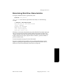
Understanding Device Special File Names
Sample Device Special File Names
Viewing System Configuration with ioscan
Terse Listing of ioscan
Understanding Hardware Addresses
Understanding the Description in ioscan
Full Listing of ioscan
Understanding Class and Instance
Card Instances and Device Files
Decoding Device Special Files with lssf
Finding Device Special Files
Using ftsmaint to Administer System Hardware
Displaying Hardware Information
1-1
1-2
1-3
1-4
1-5
1-5
1-6
1-6
1-7
1-7
1-8
1-9
1-9
1-11
1-12
1-12
1-12
1-14
1-14
2. Configuring Interface Cards
Removing and Replacing Components
Downloading Firmware
Configuring a Peripheral (A Summary)
2-1
2-1
2-2
2-6
HP-UX version 11.00.01
Contents
iii
Contents
3. Configuring Serial Ports for Terminals
and Modems
Configuring Console Controller Serial Ports
Configuring the Console Terminal
Configuring Other Terminals
3-1
3-1
3-6
3-7
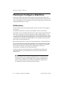
4. Configuring Disk Drives
Planning to Configure a Disk Drive
Performance
Managing Disk Devices
Adding a Disk Drive
Replacing a Broken Disk Drive
Replacing an Online Disk Drive
Moving a Disk Drive
Deleting a Disk Drive
Determining Disk Drive Characteristics
After Configuring the Disk Drive
4-1
4-2
4-2
4-3
4-3
4-4
4-6
4-8
4-11
4-13
4-14
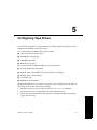
5. Configuring Tape Drives
Configuring a Tape Drive
After Configuring a Tape Drive
5-1
5-2
5-4
6. Configuring CD-ROM Drives
Configuring a CD-ROM Drive
6-1
6-2
7. Configuring Asynchronous Serial Interfaces
Hardware Support
Loading the Asynchronous Card Firmware
Creating Device Special Files
Attaching Devices to the Asynchronous Serial Interface
Cable Connection and Flow Control
DTE and DCE Controllers
Null Modem Cabling
Configuring in the Device
Configuring an Asynchronous Terminal
Modem Interface Configuration
Additional References
7-1
7-1
7-2
7-2
7-4
7-4
7-4
7-4
7-5
7-6
7-7
7-9
Index
iv
Peripherals Configuration (R1001H)
Index-1
HP-UX version 11.00.01
Figures
Figure 1-1.
Figure 1-2.
Figure 1-3.
Figure 1-4.
Figure 1-5.
Figure 1-6.
Figure 1-7.
Figure 1-8.
Figure 2-1.
Figure 2-2.
Figure 5-1.
Figure 6-1.
Figure 7-1.
Figure 7-2.
Sample Listing of ioscan
Sample ioscan -H Output
Sample ioscan -f Output
Class and Instance in ioscan Display
Device Special Files Associated with a Peripheral
ftsmaint Output
ftsmaint Output for 1/0
ftsmaint Output for 0/2/7/2
Sample download.conf File
Sample personality.conf File
Sample Continuum System ftsmaint output, LSM portion
Sample Continuum System ftsmaint output, LSM portion
ioscan -fk -C tty Command Output
Null Modem Cable Pin-Outs
HP-UX version 11.00.01
1-8
1-9
1-10
1-11
1-13
1-16
1-17
1-18
2-3
2-4
5-2
6-2
7-1
7-5
Figures
v
Tables
Table 3-1.
Table 5-1.
Table 5-2.
Console, RSN, and Auxiliary Port Configuration
Tape-Drive Commands and Special Files
Unsupported Commands
HP-UX version 11.00.01
3-2
5-4
5-6
Tables
vii
Preface <Preface>
Preface
This manual describes how to configure peripherals for Continuum systems.
Revision Information
This manual has been revised to reflect support for Continuum systems using
suitcases with the PA-8600 CPU modules, additional PCI card and storage device
models, company and platform1 name changes, and miscellaneous corrections to
existing text.
Audience
This document is intended for system administrators who install and configure the
HP-UX™ operating system.
Notation Conventions
This document uses the following conventions and symbols:
■
The following font conventions apply both to general text and to text in
displays:
–
Monospace represents text that would appear on your screen (such as
commands and system responses, functions, code fragments, file names,
directories, prompt signs, messages). For example,
Broadcast Message from ...
1. Some Continuum systems were previously called Distributed Network
Control Platform (DNCP) systems. References to DNCP still appear in some
documentation and code.
HP-UX version 11.00.01
Preface
ix
Notation Conventions
–
Monospace bold represents user input in screen displays. For example,
ls -a
■
Monospace italic represents variables in commands for which the user
must supply an actual value. For example,
cp filename1 filename2
It also represents variables in prompts and error messages for which the
system supplies actual values. For example,
cannot create temp filename filename
■
Helvetica represents all window titles, fields, menu names, and menu items in
swinstall windows and System Administration Manager (SAM) windows.
For example,
Select Mark Install from the Actions menu.
■
Italic emphasizes words in text. For example,
…does not support…
It is also used for book titles. For example,
HP-UX Operating System: Peripherals Configuration (R1001H)
■
Bold introduces or defines new terms. For example,
An object manager is an OSNM process that …
■
The notation <Ctrl> – <char> indicates a control–character sequence. To type a
control character, hold down the control key (usually labeled <Ctrl>) while you
type the character specified by <char>. For example, <Ctrl> – <c> means hold down the
<Ctrl> key while pressing the <c> key; the letter c does not appear on the screen.
■
Angle brackets (< >) enclose input that does not appear on the screen when
you type it, such as passwords. For example,
<password>
■
Brackets ([ ]) enclose optional command arguments. For example,
cflow [–r] [–ix] [–i_] [–d num] files
■
The vertical bar (|) separates mutually exclusive arguments from which you
choose one. For example,
command [arg1 | arg2]
■
Ellipses (…) indicate that you can enter more than one of an argument on a
single command line. For example,
cb [–s] [–j] [–l length] [–V] [file …]
x Peripherals Configuration (R1001H)
HP-UX version 11.00.01
Notation Conventions
■
A right-arrow (>) on a sample screen indicates the cursor position. For
example,
>install - Installs Package
■
A name followed by a section number in parentheses refers to a man page for
a command, file, or type of software. The section classifications are as follows:
–
1 – User Commands
–
1M – Administrative Commands
–
2 – System Calls
–
3 – Library Functions
–
4 – File Formats
–
5 – Miscellaneous
–
7 – Device Special Files
–
8 – System Maintenance Commands
For example, init(1M) refers to the man page for the init command used by
system administrators.
■
Document citations include the document name followed by the document
part number in parentheses. For example, HP-UX Operating System: Peripherals
Configuration (R1001H) is the standard reference for this document.
■
Note, Caution, Warning, and Danger notices call attention to essential
information.
NOTE
Notes call attention to essential information, such as tips or advice on
using a program, device, or system.
CAUTION
Caution notices alert you to conditions that could damage a program,
device, system, or data.
WARNING
Warning notices alert you to conditions that are potentially hazardous
to people. These hazards can cause personal injury if the warnings are
ignored.
HP-UX version 11.00.01
Preface
xi
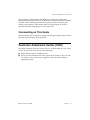
Product Documentation
DANGER
Danger notices alert you to conditions that are potentially lethal or
extremely hazardous to people.
Product Documentation
The HP-UX operating system is shipped with the following documentation:
■
HP-UX Operating System: Peripherals Configuration (R1001H) — provides
information about configuring peripherals on a Continuum system
■
HP-UX Operating System: Installation and Update (R1002H) — provides
information about installing or upgrading the HP-UX operating system on a
Continuum system
■
HP-UX Operating System: Read Me Before Installing (R1003H) — provides
updated preparation and reference information, and describes updated
features and limitations
■
HP-UX Operating System: Fault Tolerant System Administration (R1004H) —
provides information about administering a Continuum system running the
HP-UX operating system
■
HP-UX Operating System: LAN Configuration Guide (R1011H) — provides
information about configuring a LAN network on a Continuum system
running the HP-UX operating system
■
HP-UX Operating System: Site Call System User’s Guide (R1021H) — provides
information about using the Site Call System utility
■
Managing Systems and Workgroups (B2355-90157) — provides general
information about administering a system running the HP-UX operating
system (this is a companion manual to the HP-UX Operating System: Fault
Tolerant System Administration (R1004H))
Additional platform-specific documentation is shipped with complete systems
(see “Related Documentation”).
xii Peripherals Configuration (R1001H)
HP-UX version 11.00.01
Product Documentation
Online Documentation
When you install the HP-UX operating system software, the following online
documentation is installed:
■
notes files
■
manual (man) pages
Notes Files
The /usr/share/doc/RelNotes.fts file contains the final information about
this product.
The /usr/share/doc/known_problems.fts file documents the known
problems and problem-avoidance strategies.
The /usr/share/doc/fixed_list.fts file lists the bugs that were fixed in
this release.
Man Pages
The operating system comes with a complete set of online man pages. To display
a man page on your screen, enter
man name
name is the name of the man page you want displayed. The man command
includes various options, such as retrieving man pages from a specific section (for
example, separate term man pages exist in Sections 4 and 5), displaying a version
list for a particular command (for example, the mount command has a separate
man page for each file type), and executing keyword searches of the one-line
summaries. See the man(1) man page for more information.
Related Documentation
In addition to the operating system manuals, the following documentation
contains information related to administering a Continuum system running the
HP-UX operating system:
■
The Continuum Series 400-CO: Site Planning Guide (R454), the Continuum 400
Series: Site Planning Guide (R411), or the Continuum 600 and 1200 Series: Site
Planning Guide (R391) provides a system overview, site requirements (for
example, electrical and environmental requirements), cabling and connection
information, equipment specification sheets, and site layout models that can
assist in your site preparation for the respective system.
HP-UX version 11.00.01
Preface
xiii
Product Documentation
■
The HP-UX Operating System: Continuum Series 400 Hardware Installation
Guide (R002H) or the HP-UX Operating System: Continuum Series 400-CO
Hardware Installation Guide (R021H) describes how to install a complete
Continuum Series 400 or 400-CO system from unpacking the system
components to booting the machine.
■
The HP-UX Operating System: Continuum Series 400-CO Operation and
Maintenance Guide (R025H), the HP-UX Operating System: Continuum Series 400
Operation and Maintenance Guide (R001H), or the HP-UX Operating System:
Continuum Series 600 and 1200 Operation and Maintenance Guide (R024H)
provides detailed descriptions and diagrams, along with instructions about
installing and maintaining the system components for the respective system.
■
The D859 CD-ROM Drive Installation and Operation Guide (R720) or the
Continuum Series 600 and 1200: D758 CD-ROM Drive Guide (R447) describes
how to install, operate, and maintain CD-ROM drives for the respective
system.
■
The Continuum Series 400-CO: Tape Drive Operation Guide (R719), the Continuum
Series 400 and 400-CO: Tape Drive Operation Guide (R716), or the Continuum 600
and 1200 Series: Tape-Drive Operation Guide (R442) describes how to operate
and maintain tape drives for the respective system.
■
The Continuum 600 and 1200 Series: PMC-Card Installation Guide (R443) describes
how to install PMC cards into Continuum Series 600 and 1200 systems.
■
Each PCI card installation guide describes how to install that PCI card into a
Continuum system.
■
The sam(1M) man page provides information about using the System
Administration Manager (SAM).
■
For information about manuals available from Hewlett-Packard™, see the
Hewlett-Packard documentation web site at http://www.docs.hp.com.
Ordering Documentation
HP-UX operating system documentation is provided on CD-ROM (except for the
Managing Systems and Workgroups (B2355-90157) which is available as a separate
printed manual). You can order a documentation CD-ROM or other printed
documentation in either of the following ways:
■
Call the CAC (see “Customer Assistance Center (CAC)”).
■
If your system is connected to the Remote Service Network (RSN), add a call
using the Site Call System (SCS). See the scsac(1) man page for more
information.
xiv Peripherals Configuration (R1001H)
HP-UX version 11.00.01
Customer Assistance Center (CAC)
When ordering a documentation CD-ROM please specify the product and
platform documentation you desire, as there are several documentation CD-ROMs
available. When ordering a printed manual, please provide the title, the part
number, and a purchase order number from your organization. If you have
questions about the ordering process, contact the CAC.
Commenting on This Guide
Stratus welcomes any corrections or suggestions for improving this guide. Contact
the CAC to provide input about this guide.
Customer Assistance Center (CAC)
The Stratus Customer Assistance Center (CAC), is available 24 hours a day, 7 days
a week. To contact the CAC, do one of the following:
■
Within North America, call 800-828-8513.
■
For local contact information in other regions of the world, see the CAC web
site at http://www.stratus.com/support/cac and select the link for the
appropriate region.
HP-UX version 11.00.01
Preface
xv
1
Getting Started
1-
When you physically install a disk drive, tape drive, expansion cabinet, or other
peripheral device, you sometimes must configure the HP-UX operating system to
communicate with it. Many portions of a Continuum system are preconfigured and
do not require additional administrator actions, but some peripherals require
configuration in order for Continuum systems to recognize them. For many
peripherals, Stratus provides a simple value-added process that allows you to add (or
remove) peripherals dynamically without the need for an HP-UX operating system
reboot.
This manual provides the software information needed by system administrators to
configure peripheral devices supported on Continuum systems running the HP-UX
operating system.
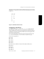
Read this chapter for:
■
an overview of peripherals configuration
■
syntax of device special file names
■
information on using ftsmaint and ioscan commands to display information
and administer hardware
NOTE
Most administrative commands and utilities reside in standard locations.
In this guide, only the command name, not the full path name, is provided
if that command resides in a standard location. The standard locations are
/usr/sbin, /bin, /usr/bin, and /etc. Full path names are provided
when the command is located in a nonstandard directory. You can
determine file locations through the find and which commands. See the
find(1) and which(1) man pages for more information.
HP-UX version 11.00.01
1-1
Peripherals and Fault Tolerant Hardware
Keep this manual, the online man pages, and any other manuals that were shipped
with your Continuum system available for reference when installing and
configuring peripheral devices.
Commands such as mksf, insf, and ioscan, as well as the Stratus value-added
ftsmaint command, make it unnecessary to manipulate the device special minor
number literally. The Stratus-developed utilities for the HP-UX operating system
provide the ftsmaint command, which provides similar functionality to the
ioscan command, but with added capabilities for administration of Stratus fault
tolerant hardware.
NOTE
Configuring a peripheral device requires that you operate with root
privileges. Exercise caution when acting as super-user.
Peripherals and Fault Tolerant Hardware
Continuum systems employ fault tolerant hardware and hot-plugging features
that simplify your tasks in configuring Continuum systems for peripheral support.
See the HP-UX Operating System: Fault Tolerant System Administration (R1004H) for
information about fault tolerant features. See the hardware documentation for
information about installing and maintaining Continuum system components.
Continuum system components are identified by hardware paths. Hardware paths
specify the addresses of the hardware components leading to specific devices.
Hardware paths consist of a numerical string of hardware addresses, notated
sequentially from the bus address to the device address. Typically, the initial
number is appended by a slash (/) to represent a bus converter or adapter and
subsequent numbers are separated by a dot (.). In order to understand how to
configure Continuum systems for peripherals, you need to know how hardware
paths map to the physical and logical hardware components. See the
“Administering Fault Tolerant Hardware” chapter in the HP-UX Operating System:
Fault Tolerant System Administration (R1004H) for information about how to
determine hardware paths.
1-2
Peripherals Configuration (R1001H)
HP-UX version 11.00.01
Peripherals and Fault Tolerant Hardware
Differences from Hewlett-Packard Systems
Stratus and Hewlett-Packard systems do not support the same set of peripheral
devices.
Continuum systems do not support the following types of peripherals and
supporting hardware:
■
floppy disk drives
■
disk arrays
■
magneto-optical devices
■
printers and plotters (except through the optional asynchronous interface)
■
graphics cards
■
ISA cards
Continuum systems do support:
■
A CD-ROM drive on the external SCSI bus. You cannot configure in a
CD-ROM drive in place of one of the base unit disk drives.
■
Adding most peripherals without shutting down and rebooting the system. If
you are familiar with using the HP-UX operating system on a
non-fault-tolerant system, you should make a special effort to familiarize
yourself with these differences.
Continuum systems differ in the way they support:
■
Uninterruptible Power Supply (UPS)
■
Modems. See Chapter 3, “Configuring Serial Ports for Terminals and
Modems,” for more information.
HP-UX version 11.00.01
Getting Started
1-3
Peripheral Configuration in Its Simplest Terms
Peripheral Configuration in Its Simplest
Terms
A peripheral device requires two or three configuration steps to communicate with
the HP-UX operating system: configure, install, and (if needed) reboot. Most
devices supported by Continuum systems do not need a system reboot to be
recognized by the system. Standard device drivers are already present in the
kernel.
1.
Configure the device drivers into the kernel.
Device drivers are like translators that speak both the language of the
peripheral device and the language of the computer. The needed device
drivers for Stratus-qualified peripherals are already part of the kernel. In some
cases, you will have to run the addhardware command to associate the
device with its driver.
2.
Install the hardware.
Perform any hardware-specific installation procedures required to physically
connect the peripheral device to your computer. Then, turn on the power to the
peripheral devices. For most peripherals associated with Continuum systems,
the HP-UX operating system will bring the device online through a process
known as hot-plugging, meaning that it is not necessary to turn off the power
to the system.
3.
Reboot the system.
The HP-UX operating system automatically creates the necessary device
special files required for the peripheral, either through Stratus-specific
commands or upon system reboot. (For most peripherals associated with
Continuum systems, special commands must be entered, but rebooting is not
necessary.) Peripherals such as disk expansion cabinets require a reboot for the
HP-UX operating system to recognize them and cannot be added dynamically
to a running Continuum system. At least one device special file must exist for
the device driver to communicate with the peripheral device. Device special
files tell the HP-UX operating system which device driver to use, how to find
the peripheral device, and what special characteristics the peripheral device
employs.
1-4
Peripherals Configuration (R1001H)
HP-UX version 11.00.01
Peripheral Configuration in Its Simplest Terms
Using SAM to Configure Peripherals
The System Administration Manager (SAM) provides the easiest way to view your
Continuum system configuration and configure the peripheral device drivers into
the kernel. To invoke SAM, enter
sam
SAM’s user interface and online help system allow you to discover the
configuration information as you proceed through its screens. Once you provide
SAM with basic information about the device being configured, SAM performs the
following steps:
1.
Checks your currently running kernel configuration file for the required
device drivers
2.
Reports whether or not the drivers are present
3.
Adds them (if necessary)
4.
Reconfigures the kernel (if necessary)
For some devices, SAM also automates other necessary steps. For example, when
adding a terminal to your Continuum system, SAM edits the /etc/inittab file
to add the terminal entry. You have to perform this step manually if you are not
using SAM to configure the terminal.
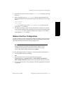
Using Commands to Configure Peripherals
You must use HP-UX operating system commands to configure peripherals to the
system if the device cannot be automatically configured or if SAM is not on your
system.
Most Stratus peripherals are configured automatically. Each peripheral-specific
chapter of this book gives procedures for using HP-UX operating system
commands and Stratus-specific commands for configuration. Most Stratus
peripherals can be configured into a running Continuum system without
rebooting.
Third-party drivers and certain drivers used for instrumentation or “black-box”
applications are not recognized by insf to create device files automatically during
the reboot process.
If you are adding a peripheral device requiring a driver that cannot be configured
automatically, you must configure the device driver and create the device files
using the ioscan and mksf or mknod commands.
Read the /usr/conf/master.d/core-hpux file and the master(4) man page for
information about the architectural-context dependencies.
HP-UX version 11.00.01
Getting Started
1-5
Understanding Device Special File Names
Understanding Device Special File Names
Device special files tell the HP-UX operating system which device driver to use,
how to find the peripheral device, and what characteristics the peripheral device
should employ. Characteristics vary by device. For example, device special files for
tape drives show rewind and density.
Most device special file names contain the location of the device on the bus
architecture. To see this, display the files in any subdirectory of the /dev directory.
Note, all mass storage devices adhere to a syntax that includes c#t#d#[s#]
(other kinds of device files use a related convention).
The c#t#d#[s#] syntax used in default device special files has the following
meaning:
c#
card instance for the ext_bus class of interface card to which the
device is attached
t#
target (SCSI address) of the disk device on the interface
d#
device unit number
s#
section number (provided for backward compatibility); the device file
addresses the entire disk (s0) when s# is unspecified
Sample Device Special File Names
Every peripheral-specific chapter in this book lists the default device special file
names for that class of device. See the “Administering Fault Tolerant Hardware”
chapter in the HP-UX Operating System: Fault Tolerant System
Administration (R1004H) for information about determining peripheral hardware
addresses.
1-6
Peripherals Configuration (R1001H)
HP-UX version 11.00.01
Viewing System Configuration with ioscan
Here are some sample device special files and their possible meanings:
/dev/rdsk/c0t2d0
Entire disk accessed in character (raw) mode
through SCSI card instance 0, target 2, LUN 0.
/dev/rmt/c1t0d0BESTnb
Tape drive accessed through card instance 1,
target 0, LUN 0. Tape writes at best available
density/format, no rewind, Berkeley-style close.
/dev/rmt/0mnb
Tape drive device special file with identical
characteristics (linked) to
/dev/rmt/c1t0d0BESTnb.
Both lssf and ioscan commands display the interface to which a device is
connected. These are discussed in the following sections.
Viewing System Configuration with ioscan
The ioscan command is the most versatile standard tool in the HP-UX operating
system for displaying your system configuration. For example, you can use
ioscan to identify available hardware addresses.
On Continuum systems, you can also use ftsmaint to identify available
hardware addresses, as well as for other administration tasks. See “Using ftsmaint
to Administer System Hardware” later in this chapter and the ftsmaint(1M) man
page for a description of ftsmaint features.
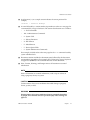
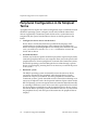
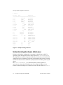
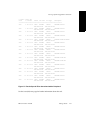
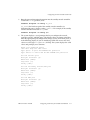
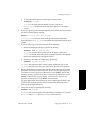
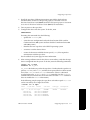
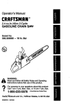
Terse Listing of ioscan
In its simplest form, ioscan displays hardware path, device class, and
description. The -u (usable devices) or -k (kernel structures) options give the
fastest response because they do not probe the hardware. See Figure 1-1 for a
sample of the output on a Continuum system.
HP-UX version 11.00.01
Getting Started
1-7
Viewing System Configuration with ioscan
# ioscan -u
H/W Path
Class
Description
====================================================
0/0/0
phys_cpus
CPU Adapter
0/0/1
phmem
MEM Adapter
0/1/0
phys_cpus
CPU Adapter
0/1/1
phmem
MEM Adapter
0/2/0/0
pcmcia
0/2/0/0.0
flash
PCMCIA Bridge
FLASH Adapter
0/2/1/0
pseudo
LAN Adapter
0/2/2/0
tty
Asyn Card
0/3/0/0
pcmcia
0/3/0/0.0
flash
0/3/3/0
tty
PCMCIA Bridge
FLASH Adapter
Asyn Card
1/0
phys_recc
RECC Adapter
1/1
phys_recc
RECC Adapter
13/0/0
lan
Lan Adapter
14/0/0.0.0
disk
SEAGATE ST15150W
14/0/0.3.0
disk
SEAGATE ST32550W
14/0/1.1.0
disk
SEAGATE ST15150W
14/0/1.2.0
disk
SEAGATE ST32550W
14/0/3.4.0
tape
HP
15/2/0
tty
15/2/1
tty
tty1
15/2/2
tty
tty2
C1557A
console
Figure 1-1. Sample Listing of ioscan
Understanding Hardware Addresses
Each piece of hardware configured to a computer is identified to the HP-UX
operating system through the hardware address (shown in ioscan as H/W Path).
The length of these numerical sequences differs by Continuum system model and
architecture, but every hardware path leads you through the bus structure, starting
from the bus closest to the Continuum system processor and ending at the output
device.
The ioscan -H hardware_path command shows you the sequence of
connection to or from the specified location. For example, in Figure 1-2, the
initiator on the SCSI adapter on a Continuum system has the address of 0/4/0/1.
1-8
Peripherals Configuration (R1001H)
HP-UX version 11.00.01
Viewing System Configuration with ioscan
# ioscan -H 0/4/0/1
H/W Path Class
Description
=======================================
0/4/0/1
ext_bus HSC SCSI Adapter
Figure 1-2. Sample ioscan -H Output
The hardware path can be decoded as follows:
0
identifies the system bus
4
identifies the location of the bus adapter connecting the device (in
this example, the HSC Nexus or high-speed communications bus)
to the system bus
0
identifies a transparent layer between the Nexus bus and the SCSI
interface
1
identifies the slot number of the SCSI interface
Field separators (slash (/) or dot (.)) separate the numbers of the hardware
address and have no bearing on system administration. The displayed classes are
more meaningful in the context of instance numbers. Instance numbers are visible
in ioscan -f listings, and are discussed later in this chapter.
Understanding the Description in ioscan
The description field displayed by ioscan derives from the peripheral device
itself, and is sometimes more cryptic than is ideal. Typically, a numeric description
refers to the manufacturer’s vendor ID, and in some cases, this number
corresponds to more than one model number. If you are troubleshooting a
peripherals problem, the description is often useful information to a Stratus
support engineer.
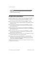
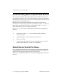
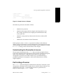
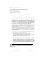
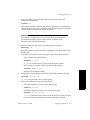
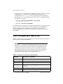
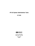
Full Listing of ioscan
The ioscan -f command displays full information about the Continuum system
configuration, including instance number, device/interface driver, software state,
and hardware type. The -fn option displays the device special files also.
Figure 1-3 shows sample ioscan -f output.
HP-UX version 11.00.01
Getting Started
1-9
Viewing System Configuration with ioscan
# ioscan -f
Class
I
H/W Path
Driver
S/W State H/W Type
Description
==========================================================================
bc
0
root
CLAIMED
BUS_NEXUS
ba
0
0
gbuscdio
CLAIMED
BUS_NEXUS
ba
1
0/0
pmerc
CLAIMED
BUS_NEXUS
PMERC Nexus
phys_cpus
0
0/0/0
merc_cpus
CLAIMED
INTERFACE
CPU Adapter
phmem
0
0/0/1
phmem
CLAIMED
INTERFACE
MEM Adapter
ba
2
0/1
pmerc
CLAIMED
BUS_NEXUS
PMERC Nexus
phys_cpus
1
0/1/0
merc_cpus
CLAIMED
INTERFACE
CPU Adapter
phmem
1
0/1/1
phmem
CLAIMED
INTERFACE
MEM Adapter
ba
3
0/4
bio
CLAIMED
BUS_NEXUS
HSC Nexus
ext_bus
16
0/4/0/1
bsha
CLAIMED
INTERFACE
HSC SCSI Adapter
ext_bus
17
0/4/0/2
bsha
CLAIMED
INTERFACE
HSC SCSI Adapter
pseudo
0
0/4/0/5
hsc
CLAIMED
INTERFACE
HSC LAN Adapter
ba
13
0/6
pci
CLAIMED
BUS_NEXUS
PCI Nexus
ba
14
0/6/1
slot
CLAIMED
BUS_NEXUS
SLOT Interface
pseudo
6
0/6/1/0
hdi
CLAIMED
INTERFACE
FDDI Adapter
ba
15
0/6/2
slot
CLAIMED
BUS_NEXUS
SLOT Interface
pseudo
2
0/6/2/0
hdi
CLAIMED
INTERFACE
LAN Adapter
GOLFBUS Nexus
ba
25
1
reccbus
CLAIMED
BUS_NEXUS
RECCBUS Nexus
phys_recc
0
1/0
recc
CLAIMED
INTERFACE
RECC Adapter
phys_recc
1
1/1
recc
CLAIMED
INTERFACE
RECC Adapter
ba
26
11
lpkiocdio
CLAIMED
BUS_NEXUS
ba
27
12
cabcdio
CLAIMED
BUS_NEXUS
CAB Nexus
ba
31
12/0
cabcdio
CLAIMED
BUS_NEXUS
Cabinet 0
cabinet
0
12/0/0
cab
CLAIMED
INTERFACE
Cabinet DataCollector0
cabinet
1
12/0/1
cab
CLAIMED
INTERFACE
Cabinet Fan0
ba
28
13
lnmcdio
CLAIMED
BUS_NEXUS
LNM Nexus
lan
0
13/0/0
lan2
CLAIMED
INTERFACE
Lan Adapter
lan
1
13/0/1
lan2
CLAIMED
INTERFACE
Lan Adapter
ba
29
14
lsmcdio
CLAIMED
BUS_NEXUS
LSM Nexus
LSM Adapter
ext_bus
0
14/0/0
lsm
CLAIMED
INTERFACE
target
0
14/0/0.0
tgt
CLAIMED
DEVICE
disk
0
14/0/0.0.0
sdisk
CLAIMED
DEVICE
target
1
14/0/0.1
tgt
CLAIMED
DEVICE
SEAGATE ST19171W
disk
1
14/0/0.1.0
sdisk
CLAIMED
DEVICE
SEAGATE ST19171W
ext_bus
2
14/0/2
lsm
CLAIMED
INTERFACE
LSM Adapter
ext_bus
3
14/0/3
lsm
CLAIMED
INTERFACE
LSM Adapter
ba
30
15
mercury
CLAIMED
BUS_NEXUS
LMERC Nexus
processor
0
15/0/0
processor
CLAIMED
PROCESSOR
Processor
processor
1
15/0/1
processor
CLAIMED
PROCESSOR
Processor
Figure 1-3. Sample ioscan -f Output
1-10
Peripherals Configuration (R1001H)
HP-UX version 11.00.01
Viewing System Configuration with ioscan
Understanding Class and Instance
The sample ioscan output in Figure 1-4 shows the ext_bus class of a sample
Continuum system. The card instance numbers are listed under I.
For device file naming and hardware mapping, the only significant instance
numbers are those associated with the INTERFACE hardware type.
# ioscan -C ext_bus -f
Class
I
H/W Path
Driver
S/W State
H/W Type
Description
==========================================================================
ext_bus
16
0/4/0/1
bsha
CLAIMED
INTERFACE
HSC SCSI Adapter
ext_bus
17
0/4/0/2
bsha
CLAIMED
INTERFACE
HSC SCSI Adapter
ext_bus
18
0/4/0/3
bsha
CLAIMED
INTERFACE
HSC SCSI Adapter
ext_bus
19
0/4/0/4
bsha
CLAIMED
INTERFACE
HSC SCSI Adapter
ext_bus
0
14/0/0
lsm
CLAIMED
INTERFACE
LSM Adapter
ext_bus
1
14/0/1
lsm
CLAIMED
INTERFACE
LSM Adapter
ext_bus
2
14/0/2
lsm
CLAIMED
INTERFACE
LSM Adapter
ext_bus
3
14/0/3
lsm
CLAIMED
INTERFACE
LSM Adapter
Figure 1-4. Class and Instance in ioscan Display
The card instance number is assigned by the HP-UX operating system to the
interface card and reflects the order that ioconfig binds that class of interface
card to its driver when it boots.
Instance is stored in two files: /etc/ioconfig and /stand/ioconfig. These
files retain their information across reboots, unless one is corrupted or missing, in
which case ioinit will rebuild the entire /dev structure. (If this occurs, you
would have to re-create any customized permissions or files.)
If you use the addhardware command to add a new hardware device, the
ioconfig files are automatically updated by the command.
HP-UX version 11.00.01
Getting Started
1-11
Viewing System Configuration with ioscan
Card Instances and Device Files
Card instance number and hardware path elements map directly into the device
special file as card instance, target number, and device number. For example, the
disk device special file /dev/dsk/c1t3d0 refers to instance one of the logical
SCSI manger (lsm), target disk with SCSI ID 3, and logical unit number (lun) of 0.
Typically, the card instance maps as the digit after the letter c (or for terminals, the
number after tty).
Note, the card instance designated in the device special file refers to the interface
card, not to the instance number of the peripheral device attached to the card. The
card instance number is unique only for the specific class (for example, ext_bus)
of interface. Thus, for example, the tty class of interface has its own sequence of
card instance numbers, beginning with zero, which appear in its device files.
Decoding Device Special Files with lssf
Use the lssf command to decode device special files, as in the following
Continuum Series 400 example:
# lssf /dev/lan
streams cloneable pseudo driver dlpi /dev/lan
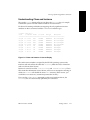
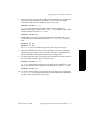
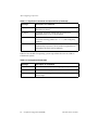
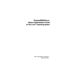
Finding Device Special Files
You can use ioscan -fn (or -fkn or -fun) to show device special file names
associated with a peripheral. You can also add other ioscan options (such as -H,
-C, -d, or -I) to limit your output to specific elements in your configuration.
The example in Figure 1-5, using -C disk, shows the device files available for the
disk class, as well as the location and type of disk device.
1-12
Peripherals Configuration (R1001H)
HP-UX version 11.00.01
Viewing System Configuration with ioscan
# ioscan -C disk -fun
Class
I
H/W Path
Driver
S/W State
H/W Type
Description
======================================================================
disk
0
14/0/0.1.0
sdisk
CLAIMED
/dev/dsk/c0t1d0
disk
1
14/0/0.2.0
sdisk
CLAIMED
/dev/dsk/c0t2d0
disk
2
14/0/0.3.0
sdisk
CLAIMED
/dev/dsk/c0t3d0
disk
3
14/0/0.4.0
sdisk
CLAIMED
/dev/dsk/c0t4d0
disk
4
14/0/0.5.0
sdisk
CLAIMED
/dev/dsk/c0t5d0
disk
5
14/0/1.0.0
sdisk
CLAIMED
/dev/dsk/c1t0d0
disk
6
14/0/1.1.0
sdisk
CLAIMED
/dev/dsk/c1t1d0
disk
7
14/0/1.2.0
sdisk
CLAIMED
/dev/dsk/c1t2d0
disk
8
14/0/1.3.0
sdisk
CLAIMED
/dev/dsk/c1t3d0
disk
9
14/0/1.4.0
sdisk
CLAIMED
/dev/dsk/c1t4d0
disk
10
14/0/1.5.0
sdisk
CLAIMED
/dev/dsk/c1t5d0
disk
11
14/0/2.0.0
sdisk
CLAIMED
/dev/dsk/c2t0d0
disk
12
14/0/2.1.0
sdisk
CLAIMED
/dev/dsk/c2t1d0
disk
13
14/0/2.2.0
sdisk
CLAIMED
/dev/dsk/c2t2d0
disk
14
14/0/2.3.0
sdisk
CLAIMED
/dev/dsk/c2t3d0
disk
15
14/0/2.4.0
sdisk
CLAIMED
/dev/dsk/c2t4d0
DEVICE
SEAGATE ST19171W
/dev/rdsk/c0t1d0
DEVICE
SEAGATE ST19171W
/dev/rdsk/c0t2d0
DEVICE
SEAGATE ST19171W
/dev/rdsk/c0t3d0
DEVICE
SEAGATE ST34573WC
/dev/rdsk/c0t4d0
DEVICE
TOSHIBA CD-ROM XM-3801TA
/dev/rdsk/c0t5d0
DEVICE
SEAGATE ST34371W
/dev/rdsk/c1t0d0
DEVICE
SEAGATE ST39173WC
/dev/rdsk/c1t1d0
DEVICE
SEAGATE ST39173WC
/dev/rdsk/c1t2d0
DEVICE
SEAGATE ST39173WC
/dev/rdsk/c1t3d0
DEVICE
SEAGATE ST118273WC
/dev/rdsk/c1t4d0
DEVICE
SEAGATE ST118273WC
/dev/rdsk/c1t5d0
DEVICE
SEAGATE ST19171W
/dev/rdsk/c2t0d0
DEVICE
SEAGATE ST19171W
/dev/rdsk/c2t1d0
DEVICE
SEAGATE ST19171W
/dev/rdsk/c2t2d0
DEVICE
SEAGATE ST19171W
/dev/rdsk/c2t3d0
DEVICE
SEAGATE ST19171W
/dev/rdsk/c2t4d0
Figure 1-5. Device Special Files Associated with a Peripheral
See the ioscan(1M) man page for further information about this tool.
HP-UX version 11.00.01
Getting Started
1-13
Using ftsmaint to Administer System Hardware
Using ftsmaint to Administer System
Hardware
The ftsmaint command is the primary utility for managing Continuum system
hardware components. The ftsmaint command provides a variety of services
such as the following:
■
displays hardware configuration and status information (similar to ioscan)
■
enables or disables hardware devices
■
synchronizes paired components (for example, duplexing/unduplexing
CPU/memory boards or switching online/standby console controllers)
■
burns board-resident PROM code
■
configures mean-time-between-failure (MTBF) settings
To view a list of command options, enter
ftsmaint -h
See the ftsmaint(1M) man page for a description of all options. See the
“Administering Fault Tolerant Hardware” chapter in the HP-UX Operating System:
Fault Tolerant System Administration (R1004H) for examples of using ftsmaint to
accomplish various administrative tasks.
NOTE
Use the addhardware command to add new peripheral components to
your Continuum system; use ftsmaint to remove or replace peripheral
components.
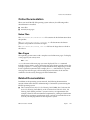
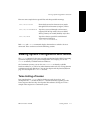
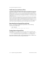
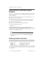
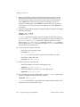
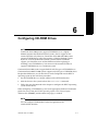
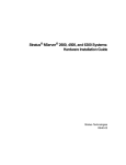
Displaying Hardware Information
The ls option displays information about the Continuum system configuration,
including instance number, device/interface driver, software state, and hardware
type. To view configuration and status information, enter one of the following:
ftsmaint ls
ftsmaint ls -l
ftsmaint ls hw_path
[short listing of all components]
[long listing of all components]
[long listing for hw_path]
hw_path is the hardware path for a specific component. The fields in a long listing
vary according to the type of component. Figure 1-6 shows a sample short listing
of all components.
1-14
Peripherals Configuration (R1001H)
HP-UX version 11.00.01
Using ftsmaint to Administer System Hardware
# ftsmaint ls
Modelx H/W Path
Description
State Serial#
PRev Status
FCode Fct
================================================================================
-
CLAIM -
-
Online
-
0
GOLFBUS Nexus
CLAIM -
-
Online
-
0
g31100 0/0
PMERC Nexus
CLAIM 10432
9.0
Online
-
0
-
0/0/0
CPU Adapter
CLAIM -
-
Online
-
0
m70700 0/0/1
MEM Adapter
CLAIM -
-
Online
-
0
g31100 0/1
PMERC Nexus
CLAIM 10414
9.0
Online
-
0
-
0/1/0
CPU Adapter
CLAIM -
-
Online
-
0
m70700 0/1/1
MEM Adapter
CLAIM -
-
Online
-
0
k46000 0/4
HSC Nexus
CLAIM 3718
18.2 Online
-
0
-
0/4/0/1
HSC SCSI Adapter W/S CLAIM -
-
Online
-
0
-
0/4/0/2
HSC SCSI Adapter W/S CLAIM -
-
Online
-
0
-
0/4/0/3
HSC SCSI Adapter SE
CLAIM -
-
Online
-
0
-
0/4/0/4
HSC SCSI Adapter SE
CLAIM -
-
Online
-
0
-
0/4/0/5
HSCENET Adapter
CLAIM -
-
Online
-
0
-
0/4/0/6
Hawaii Cabinet
CLAIM -
-
Online
-
0
e57500 0/4/0/6/0
Oahu Module
CLAIM -
-
Online
-
0
-
Hawaii Cabinet
CLAIM -
-
Online
-
0
e57500 0/4/0/7/0
Oahu Module
CLAIM -
-
Online
-
0
-
0/4/0/8
Hawaii Cabinet
CLAIM -
-
Online
-
0
-
0/4/0/9
Hawaii Cabinet
CLAIM -
-
Online
-
0
-
1
RECCBUS Nexus
CLAIM -
-
Online
-
0
e59300 1/0
RECC Adapter
CLAIM 10432
18.0 Online
-
0
e59300 1/1
RECC Adapter
CLAIM 10414
18.0 Online
-
0
CLAIM -
-
Online
-
0
0
-
0
0/4/0/7
-
11
-
11/10
LPKIO NEXUS
CLAIM -
-
Online
-
k11800 11/10/9
k118 adapter
CLAIM 10934
-
Online
-
0
k11200 11/10/10
RSE 2-port K112: tem CLAIM -
-
Online
-
0
k11200 11/10/11
RSE 2-port K112: tem CLAIM -
-
Online
-
0
k11800 11/10/12
k118 adapter
CLAIM 11326
-
Online
-
0
k11800 11/10/13
k118 adapter
CLAIM 10833
-
Online
-
0
-
11/10/14
PK Terminator
CLAIM -
-
Online
-
0
-
11/10/15
PK Terminator
CLAIM -
-
Online
-
0
-
12
CAB Nexus
CLAIM -
-
Online
-
0
-
12/0
Central Equip Cabine CLAIM -
-
Online
-
0
e59000 12/0/0
Cabinet Data Collect CLAIM 12667
-
Online
-
0
e68400 12/0/1
Cabinet Fan 0
CLAIM -
-
Online
-
0
e68400 12/0/2
Cabinet Fan 1
CLAIM -
-
Online
-
0
ax6100 12/0/7
Cabinet Air Filter 0 CLAIM -
-
Online
-
0
HP-UX version 11.00.01
Getting Started
1-15
Using ftsmaint to Administer System Hardware
p21400 12/0/8
AC Power Controller
CLAIM -
-
Online
-
0
p21400 12/0/10
AC Power Controller
CLAIM -
-
Online
-
0
p20600 12/0/12
Power Supply Unit 0
CLAIM -
-
Online
-
0
p20600 12/0/13
Power Supply Unit 1
CLAIM -
-
Online
-
0
-
13
LNM Nexus
CLAIM -
-
Online
-
0
-
13/0/0
LAN Adapter
CLAIM -
0
Online
-
0
-
13/0/1
LAN Adapter
CLAIM -
0
Online
-
0
-
14
LSM Nexus
CLAIM -
-
Online
-
0
-
14/0/0
LSM Adapter
CLAIM -
-
Online
-
0
-
14/0/0.0
CLAIM -
-
Online
-
0
d70600 14/0/0.0.0
-
SEAGATE ST19171W
14/0/0.1
CLAIM -
-
Online
-
0
CLAIM -
-
Online
-
0
0
d70520 14/0/0.1.0
SEAGATE ST34371W
CLAIM -
-
Online
-
-
14/0/1
LSM Adapter
CLAIM -
-
Online
-
0
-
14/0/1.0
CLAIM -
-
Online
-
0
d70600 14/0/1.0.0
-
SEAGATE ST19171W
14/0/1.1
d70520 14/0/1.1.0
-
Online
-
0
-
Online
-
0
CLAIM -
-
Online
-
0
CLAIM -
-
Online
-
0
SEAGATE ST32171W
CLAIM -
-
Online
-
0
LSM Adapter
CLAIM -
-
Online
-
0
14/0/3
LSM Adapter
CLAIM -
-
Online
-
0
-
15
LMERC Nexus
CLAIM -
-
Online
-
0
-
15/0/0
Processor
CLAIM -
-
Online
-
0
-
15/1/0
Memory
CLAIM -
-
Online
-
0
-
15/2/0
console
CLAIM -
-
Online
-
0
-
14/0/1.4
-
14/0/1.4.0
-
14/0/2
-
SEAGATE ST34371W
CLAIM CLAIM -
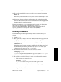
Figure 1-6. ftsmaint Output
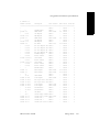
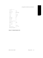
Figure 1-7 and Figure 1-8 are sample long listings for two components, a console
controller and a SCSI adapter card.
NOTE
The reported fields differ somewhat for these components.
1-16
Peripherals Configuration (R1001H)
HP-UX version 11.00.01
Using ftsmaint to Administer System Hardware
# ftsmaint ls 1/0
H/W Path
: 1/0
Device Name
: reccs
Description
: RECC Adapter
Class
: phys_reccs
Instance
: 0
State
: CLAIMED
Status
: Online
Modelx
: e593
Sub Modelx
: 00
Board Type
: 0
Board Rev
: 59
Art Rev
: 0
Min Partner Revision: 0
Firmware Rev
: 18.0
Serial#
: 10432
Fault Count
: 0
Fault Code
: -
MTBF
: Infinity
MTBF Threshold
: 600 Seconds
Weight. Soft Errors : 1
Min. Number Samples : 6
Figure 1-7. ftsmaint Output for 1/0
HP-UX version 11.00.01
Getting Started
1-17
Using ftsmaint to Administer System Hardware
# ftsmaint ls 0/2/7/2
H/W Path
: 0/2/7/2
Partner H/W Path
: 0/3/7/2
Device Name
: dpt
Description
: SCSI Adapter W/SE
Class
: ext_bus
Instance
: 18
State
: CLAIMED
Status
: Online Duplexed
Modelx
: u501
Sub Modelx
: 00
Firmware Rev
: 0ST5
Serial#
: 42-000643
PCI Vendor ID
: 0x1044
PCI Device ID
: 0xA400
Fault Count
: 0
Fault Code
: -
MTBF
: Infinity
MTBF Threshold
: 600 Seconds
Weight. Soft Errors : 1
Min. Number Samples : 6
Figure 1-8. ftsmaint Output for 0/2/7/2
1-18
Peripherals Configuration (R1001H)
HP-UX version 11.00.01
2
Configuring Interface Cards
2-
This chapter discusses removing and replacing components, and downloading
firmware. It ends with a summary on configuring a peripheral.
Removing and Replacing Components
The HP-UX operating system adds components to the system structure at boot time
by inventorying the existing Continuum hardware components and configuring the
system accordingly. Once the system is running, you can use the ftsmaint
command to remove and replace Continuum hardware components or the
addhardware command to add new hardware to a running system.
When replacing Customer Replacable Units (CRUs), the following restrictions apply:
■
When removing a hardware component, you must replace it with another
component of the same type.
■
The addhardware command allows you to add a new hardware component to
a running system without needing to manually step through remaking the kernel
or rebooting the system. See the HP-UX Operating System: Fault Tolerant System
Administration (R1004H) and the mk_kernel(1M), flifcp(1M), and flashdd(1M) man
pages.
■
To prevent unpredictable system behavior, issue an ftsmaint disable and
following enable command to disconnect it from its software link before
removing a hardware component.
A newly replaced CRU undergoes diagnostic self-test. If it passes diagnostics and
satisfies configuration constraints, the resources contained in that component are
made available to the system.
HP-UX version 11.00.01
2-1
Downloading Firmware
Downloading Firmware
On Continuum systems a user-level daemon is responsible for downloading
firmware. This daemon is downloadd. See the downloadd(1M) man page for
additional information. This daemon is used to download firmware for the Async,
SDLC, and X.25 protocols.
Each time the system boots, downdloadd is started and performs its designated
actions, including:
■
renaming the logfile /var/adm/download.log to
/var/adm/download.log.OLD
■
registering the protocol with FTS
■
receiving notification from FTS and performing the protocol-specific action
whenever a downloadd-defined card is removed, inserted, disabled, or
removed
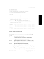
To perform these actions, downloadd downloads firmware by executing
commands in the /etc/stratus/download.conf configuration file. Figure 2-1
shows a sample download.conf file.
2-2
Peripherals Configuration (R1001H)
HP-UX version 11.00.01
Downloading Firmware
/etc/stratus/download.conf
--------------------------# This is a configuration file for Continuum Series 400 hardware
# Key hw_path fw_path Modelx personality event command
# Async Card
F * - u45000
-
INI "/usr/sbin/asyndload -i $INST"
C - - -
-
ENA "/usr/sbin/asyndload -i $INST"
C - - -
-
ACT "/usr/sbin/asyndload -i $INST"
F * - k11800
INI "/usr/sbin/kdload -d /dev/diag/mux$INST -f \
/etc/stratus/prom_code/ioa18_async.pm"
C - - ENA "/usr/sbin/kdload -d /dev/diag/mux$INST -f \
/etc/stratus/prom_code/ioa18_async.pm"
C - - ACT
"/usr/sbin/kdload -d /dev/diag/mux$INST -f \
/etc/stratus/prom_code/ioa18_async.pm"
# ARTIC RSE
F * * u40300
RSE INI "/usr/sbin/articdload -p $HW_PATH -d /dev/psdbg -c $FW_PATH"
C - - -
-
ENA "/usr/sbin/articdload -p $HW_PATH -d /dev/psdbg -c $FW_PATH"
C - - -
-
ACT "/usr/sbin/articdload -p $HW_PATH -d /dev/psdbg -c $FW_PATH"
# ARTIC RSE
F * * u40400
RSE INI "/usr/sbin/articdload -p $HW_PATH -d /dev/psdbg -c $FW_PATH"
Figure 2-1. Sample download.conf File
The fields in the /etc/stratus/download.conf file have the following
meanings:
Key
Indicates the status of the entry.
F specifies the start of a new firmware download entry.
C specifies the continuation of the above entry.
hw_path
A logical hardware path, an asterisk (*), or a dash (-). “*” or “-”
specifies all paths from the I/O tree for the device model in the
Modelx field on the same line.
fw_path
Full path of firmware file to be downloaded.
Modelx
The device model, such as u45000 for the U450 Async card.
personality Personality for the listed device model and hardware path
specified in the /etc/stratus/personality.conf file. When
the personality field is filled, downloadd reads the
/etc/stratus/personality.conf file to obtain the hardware
HP-UX version 11.00.01
Configuring Interface Cards
2-3
Downloading Firmware
paths. The hardware paths are identified when entry in the
Modelx field and the entry in the personality field from the
download.conf file match the entry in the Modelx field and the
entry in the personality field from the personality.conf
file.
A Fault Tolerant Service (FTS) event, such as initiating, enabling,
disabling, activating, or deactivating the device. The event
determines when the actions specified in the command field will
be executed.
event
INI means start the daemon (of the specified protocol)
ENA means enable the device
DIS means disable the device
ACT means insert the device
DEA means remove the device
Command to be executed for the event specified in event field.
command
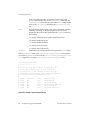
If the personality field in the /etc/stratus/download.conf file contains
an asterisk (*), downloadd also reads the /etc/stratus/personality.conf
file. Figure 2-2 is a sample /etc/stratus/personality.conf file.
/etc/stratus/personality.conf
----------------------------#
# This file is used by downloadd deamon. If personality is set
# for any modelx in download.conf file and its hardware path
# is not specified ( *), then the deamon uses this file to get
# exact hardware path and firmware file name. Modelx and personality
# are matched from this file and download.conf file.
#
#
Modelx
Personality
Hw_path
Firmware_file_name
#
u40300
X25
0/2/3/0
/etc/x25/u400.dwn
#
u40400
DLC
0/3/5/0
/etc/opt/sna/u400.dwn
#
u40400
RSE
0/3/6/0
/etc/artic/rse_firmware.coff
#
k10200
X25
11/8/6
/etc/x25/ucomm_x25.pm
#
k11200
DLC
11/6/10
/etc/opt/sna/ucomm_dlc.pm
Figure 2-2. Sample personality.conf File
2-4
Peripherals Configuration (R1001H)
HP-UX version 11.00.01
Downloading Firmware
The fields in the /etc/stratus/personality.conf file have the same
purpose and meaning as the fields in the /etc/stratus/download.conf file.
New cards with a Modelx entry configured in the
/etc/stratus/download.conf can be added any time. Whenever a new card
is added, downloadd:
■
identifies the new device
■
determines if the model for the device is present in the download.conf file
Modelx field
■
downloads the firmware as specified in the command field when INI is in the
event field for the model in the download.conf file
To add a new device when the model of the device is not listed in the Modelx field:
1.
Add an entry for the new model in the download.conf file (be sure to
include the new specification for the Modelx field).
2.
Issue the following command to reread the configuration file:
downloadd -rescan
Whenever a new type of card is added and a new entry is added in the Modelx
field, this command line initiates the downloadd daemon. downloadd
identifies the new cards and downloads firmware as specified in the command
field when INI is in the event field for the model in the download.conf file.
The downloadd command options include:
-kill Kill the running downloadd daemon.
-rescan Reread the /etc/stratus/download.conf configuration file
-h Help messages
If you want to burn different firmware to a board in a particular slot, you need to
configure download.conf and personality.conf.
For example, to burn new firmware to the K118 device in a specific slot, you must
add entries to download.conf and personality.conf.
In download.conf, add the following entries for the K118 device:
F * - k11800 ALD INI "kdload -d /dev/diag/mux$INST -f $FW_PATH"
C * - k11800 ENA "kdload -d /dev/diag/mux$INST -f $FW_PATH"
C * - k11800 ACT "kdload -d /dev/diag/mux$INST -f $FW_PATH"
In personality.conf, add the following entries for the particular firmware and
slot desired for the K118 device:
k11800 ALD 11/10/12 /etc/stratus/prom_code/ioa18_async.pm
k11800 ALD 11/10/16 /etc/stratus/prom_code/ioa18_async.pm
HP-UX version 11.00.01
Configuring Interface Cards
2-5
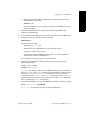
Configuring a Peripheral (A Summary)
In this case, 11/10/12 is the desired slot for the K118 device, and
/etc/stratus/prom_code/ioa18_async.pm is the firmware file name you
want to burn on this device.
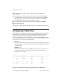
Configuring a Peripheral (A Summary)
First, prepare for configuring the peripheral by gathering information required for
the successful configuration of the peripheral. The considerations vary depending
on the peripheral type and are discussed in each peripheral-specific chapter. For
example:
■
Have you prepared the location for the peripheral device?
■
To what interface are you connecting the peripheral?
■
What device drivers are required by the peripheral device?
The System Administration Manager (SAM) and the addhardware command
provide a simple interface for configuring the HP-UX operating system for
standard peripheral devices.
On Continuum systems, the kernel is automatically loaded back into the LIF when
the mk_kernel command is invoked or the system is rebooted. The
addhardware command automatically runs the system utilities needed to remake
the kernel and bring the new device online. This operation can be performed on a
running system. There is no need to reboot the Continuum system to add new
replacement hardware. SAM will also automatically reburn the flash card on
Continuum Series 400 systems.
Here is how to update the Continuum system for most standard devices, or most
additional and replacement devices of a previously configured type:
1.
Configure system components for the new peripheral according to your
hardware documentation.
2.
Power on the peripheral device(s).
3.
Run the addhardware command. The HP-UX operating system will scan for
the new hardware and make the necessary updates to the HP-UX operating
system file. The device special files required by the new peripheral device will
be created in the appropriate /dev directories.
4.
Verify the configuration by invoking the ioscan command (see the
ioscan(1M) man page for more information).
2-6
Peripherals Configuration (R1001H)
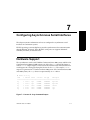
HP-UX version 11.00.01
3
Configuring Serial Ports for Terminals
and Modems
3-
This chapter contains the procedures for configuring serial ports and related
terminals and modems on a Continuum system. For the HP-UX operating system to
communicate with a terminal or modem, the following conditions must be met:
■
The serial device driver that is required to communicate with the device must be
configured into the kernel.
■
The terminal or modem must be attached and configured to the port.
■
A device special file must be created to communicate through the port.
■
A getty process must be run against the (terminal) port to solicit logins.
Configuring Console Controller Serial Ports
Stratus provides a default configuration for the ports supported by the console
controller. (See the “Getting Started” chapter in the HP-UX Operating System: Fault
Tolerant System Administration (R1004H) for a description of console controller
features.) However, you might need to change the configuration at some point. This
section describes how to properly configure the console port(s) and terminal to
communicate with your system.
See Chapter 7, “Configuring Asynchronous Serial Interfaces,” for information about
configuring asynchronous serial ports off other cards. See the “Remote Service
Network” chapter in the HP-UX Operating System: Fault Tolerant System
Administration (R1004H) for information about configuring the Remote Service
Network (RSN).
HP-UX version 11.00.01
3-1
Configuring Console Controller Serial Ports
The console controllers support three serial ports, a console port, a port reserved
for the RSN modem, and an auxiliary port that you can use for various purposes
(for example, an external UPS). The ports are located on the back of the system base
or cabinet in a Continuum system. The port assignments are as follows:
Port 0
Console
Port 1
Remote Service Network (RSN)
Port 2
Auxiliary port (for UPS or secondary console)
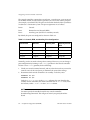
By default, the ports are configured as shown in Table 3-1.
Table 3-1. Console, RSN, and Auxiliary Port Configuration
Console Port
RSN Port
Auxiliary Port
Auxiliary Port for
UPS
9600 baud
9600 baud
9600 baud
2400 baud
7 bits
7 bits
7 bits
8 bits
odd parity
odd parity
odd parity
no parity
1 stop bit
1 stop bit
1 stop bit
1 stop bit
Normally, you do not need to change these settings. However, you can change a
port configuration by burning a new config partition in the console controller.
To burn a new config partition, do the following:
1.
Check your console terminal manual, and any other devices that you need to
connect to one of the serial ports, to determine the correct line settings.
2.
Determine which console controller is on standby. To do this, enter
ftsmaint ls 1/0
ftsmaint ls 1/1
Look for Online Standby in the Status column; this state identifies the
standby console controller (the online controller lists an Online state). Note
the location, either 1/0 or 1/1 in the H/W Path column.
NOTE
You must specify the standby board for any console controller
board-burning commands. You will get an error if you specify the online
board.
3-2
Peripherals Configuration (R1001H)
HP-UX version 11.00.01
Configuring Console Controller Serial Ports
3.
Burn the port configuration information into the standby console controller.
To burn the config partition, enter
ftsmaint burnprom -F config hw_path
hw_path is the hardware path of the standby console controller (as
determined in step 2), which is either 1/0 or 1/1. For example, if the standby
console controller is located at 1/0, enter
ftsmaint burnprom -F config 1/0
4.
The system displays a set of prompts that let you configure the console,
secondary console, and RSN ports. The default values are shown in brackets.
Enter the appropriate port configuration changes (if any) for all three ports, as
in the following display. If you are modifying a field and are not sure what
values are valid, type help (or h or ?) for help. The system displays the valid
values and prompts you to continue.
Enter your modified values
<CR> will keep the same value
Type ‘quit’ to quit and UPDATE the partition
Type ‘abort’ to abort and DO NOT UPDATE the partition
For the Console port
Bits per character [7]:
Baud rate [9600]:
Stop bits [1]:
Parity [odd]:
For the Secondary Console/UPS port
Bits per character [7]:
Baud rate [9600]:
Stop bits [1]:
Parity [odd]:
For the RSN port
Bits per character [7]:
Baud rate [9600]:
Stop bits [1]:
Parity [odd]:
HP-UX version 11.00.01
Configuring Serial Ports for Terminals and Modems
3-3
Configuring Console Controller Serial Ports
5.
The system next displays the following three prompts:
power up on boot [1]:
allow host config [0]:
shadow console setup [0]:
To change a default value, enter the new value at the appropriate prompt.
These prompts serve the following purposes:
–
The power up on boot prompt allows you to set whether the system
automatically powers up when power is restored to the system after being
shut down. By default (1) the system powers up automatically when
booting; that is, the console controller turns on power to all of the other
boards in the system. Alternatively, if you enter 0 at this prompt, the
system will not power up at boot, but will immediately enter the console
command menu and wait for the administrator to enter a command. The
power up on boot prompt applies to Continuum Series 600 and 1200
systems only; it has no effect on Continuum Series 400 systems.
–
The allow host config prompt sets whether the host can override the
configuration settings for the console port. (This setting applies to the
secondary port if the shadow console setup value is set to 1 or 2.) By
default (0), only the port configuration values read from the config
partition are used; requests from the host to change the port configuration
are ignored. To allow the host to specify a different port configuration,
enter 1 at this prompt.
–
The shadow console setup prompt sets the function of the auxiliary
port. You can enter one of the following values:
0
Do not enable the secondary console port (the default).
1
Enable the secondary console port as a shadow to the main console,
and report all input and output from the main console.
2
Enable the secondary console port as a shadow to the main console
port, but report output only from the main console (discard input).
3
Enable the secondary console port as a fully independent channel.
4
Enable the secondary console port as a UPS connection port. (Connect
the UPS directly to this port; no other configuration is necessary.)
NOTE
For information on installing a UPS, see your hardware installation
documentation.
3-4
Peripherals Configuration (R1001H)
HP-UX version 11.00.01
Configuring Console Controller Serial Ports
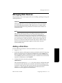
6.
To activate the new settings, the standby console controller you just updated
must become the online console controller. To switch the status of both
controllers (online becomes standby and vice versa), enter
ftsmaint switch hw_path
hw_path is the hardware path of the standby console controller (as
determined in step 2), which is either 1/0 or 1/1. For example, if the standby
console controller is located at 1/0, enter
ftsmaint switch 1/0
7.
Check that the status of the newly updated console controller board is Online
and that the other console controller board is Online Standby. To do this,
enter
ftsmaint ls 1/1
ftsmaint ls 1/0
The Status values should be the opposite of those observed in step 2.
8.
Update the PROM code on the console controller that is now on standby by
repeating steps 3–5 for this console controller. Once this is completed, both
console controllers will be updated with the new configuration.
9.
To return the boards to the state in which you found them, switch the status of
the two console controllers again. To do this, enter
ftsmaint switch hw_path
hw_path is the hardware path of the new standby console controller (as set in
step 6). For example, if the standby console controller is located at 1/1, enter
ftsmaint switch 1/1
10. To verify that the boards have returned to the appropriate state, and that the
Firmware Rev has been updated with the revision number of the PROM files
you just used to update them, repeat step 2.
HP-UX version 11.00.01
Configuring Serial Ports for Terminals and Modems
3-5
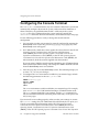
Configuring the Console Terminal
Configuring the Console Terminal
The addhardware command detects any new terminals added to the system and
automatically configures them into the system, without need for shutdown or
reboot. Therefore, any qualified terminal with a valid entry in the system
terminfo file can be configured into the system simply by running the
addhardware command. For more information, see the addhardware(1) man page.
Use the following procedure to verify or change the console terminal
configuration:
1.
You can make sure that your terminal is properly configured by entering the
Quick Setup screen. To do this, press the <F1>, <Ctrl>-<F3>, or <Ctrl>-<Select> keys. The
Quick Setup screen will appear.
2.
For V105 consoles, check these values against the values shown in the HP-UX
Operating System: Continuum Series 400 Operation and Maintenance
Guide (R001H), the HP-UX Operating System: Continuum Series 400-CO
Operation and Maintenance Guide (R025H), or the HP-UX Operating System:
Continuum Series 600 and 1200 Operation and Maintenance Guide (R024H); for
other terminals, check the manual supplied with that terminal.
If you are using a V105, the console terminal should be set to VT320 emulation
mode (which is the default setting). The setting for VT300-7 should be selected
from the Quick Setup screen at installation.
3.
Press the <Pause> key to exit the Quick Setup screen. The terminal prompts you
to enter Y or y to save your changes.
4.
To configure the TERM environment variable for your terminal type, include
the following parameters in the root /.profile file:
TERM=terminal_type
export TERM
tput init
tabs
The TERM environment variable establishes your terminal type. For example,
enter TERM=vt320 for a V105 terminal running in VT320 emulation mode.
The tput command initializes your terminal, and the tabs command sets
tabs. For detailed information concerning these commands, see the tput(1) and
tabs(1) man pages.
If your console is not working properly, make sure that your settings are correct.
The terminfo settings for your V105 terminal should already be set up for you.
Consult your terminal documentation and the HP-UX Operating System:
Continuum Series 400 Operation and Maintenance Guide (R001H), the HP-UX
Operating System: Continuum Series 400-CO Operation and Maintenance Guide
(R025H), or the HP-UX Operating System: Continuum Series 600 and 1200 Operation
3-6
Peripherals Configuration (R1001H)
HP-UX version 11.00.01
Configuring Other Terminals
and Maintenance Guide (R024H) for more information on terminal setup and
settings. If you lose communication with the system, also check the serial cable
connections.
Configuring Other Terminals
As noted in the preceding section, “Configuring the Console Terminal,” you can
configure a new terminal into the system simply by running the addhardware
command. Use the following procedure to add a new entry to the terminfo
directory or to set up an individual’s environment to use a specific terminal.
1.
If this is not a Hewlett-Packard terminal, make sure the fileset1 NONHPTERM is
on the system by using either of these methods:
–
swlist -l fileset NonHP-Terminfo
If the fileset exists, the entry for NonHP-Terminfo.NONHPTERM appears.
–
ll /usr/adm/sw/products/NonHP-Terminfo
If the fileset exists, the directory
/usr/adm/sw/products/NonHP-Terminfo/NONHPTERM exists.
If the fileset is not on the system, you need to load it from your HP-UX
operating system media. For more information, see the swinstall(1M) man
page.
2.
Look in the directory /usr/share/lib/terminfo for a file that
corresponds to the terminal you want to set up.
For example, suppose you want to set up a user with a Wyse™ 100 terminal.
All supported terminals whose names begin with w are contained in the
/usr/share/lib/terminfo/w directory. Because this directory contains a
wy100 entry, you have probably found the correct file. To be sure, examine the
contents of the file. You will see a full screen of special characters, but near the
beginning you will see wy100|100|wyse 100. This verifies the correct file
and shows that you can refer to the Wyse 100 by any of the names wy100, 100,
or wyse 100.
If you find a file for the terminal you have, skip to step 4.
If you do not find a terminfo file for your type of terminal, you need to create
one. Go to step 3.
1. A fileset is a collection of files that make up a particular product or option.
A fileset is the software object upon which most SD-UX software
management operations, like swinstall, are performed.
HP-UX version 11.00.01
Configuring Serial Ports for Terminals and Modems
3-7
Configuring Other Terminals
3.
To create a new terminfo file, follow the directions in the terminfo(4) man
page.
To adapt an existing terminfo file, follow these steps:
a.
Log in as super-user.
b.
Make an ASCII copy of an existing terminfo file. For example, to copy
the file /usr/share/lib/terminfo/w/wy100, enter
untic wy100 > new_file
c.
Edit the new file to reflect the capabilities of the new terminal. Make sure
you change the name(s) of the terminal in the first line.
d. Compile the new terminfo file. To do this, enter
tic new_file
For more information, see the tic(1M) and untic(1M) man pages.
4.
Set the user’s TERM variable in the appropriate login script (either .profile
for Korn and POSIX shell users or .login for C shell users). For example, to
specify a Wyse 100 terminal, enter one of the following:
export TERM=wy100 (Korn or POSIX shell)
setenv TERM wy100 (C shell)
The default versions of these scripts prompt the user for the terminal type
when they log in. If you are unable to edit the script, tell the user to type the
terminal name at the prompt. For example, to specify a Wyse 100 terminal,
enter
TERM = (hp) wy100
You can also set the TERM variable with the ttytype command. For more
information, see the ttytype(1) man page.
3-8
Peripherals Configuration (R1001H)
HP-UX version 11.00.01
4
Configuring Disk Drives
4-
This chapter gives procedures and guidelines for configuring disk drives using the
SCSI interface. When configuring a disk drive, have available the following
additional documentation:
■
HP-UX Operating System: Fault Tolerant System Administration (R1004H)
■
HP-UX Operating System: Continuum Series 400 Operation and Maintenance
Guide (R001H), HP-UX Operating System: Continuum Series 400-CO Operation and
Maintenance Guide (R025H), HP-UX Operating System: Continuum Series 600 and
1200 Operation and Maintenance Guide (R024H)
■
Managing Systems and Workgroups (B2355-90157)
■
online man pages
■
pertinent hardware documentation for the computer, device adapter, and
peripheral device
■
record of your disk configuration
See the “Administering Fault Tolerant Hardware” chapter in the HP-UX Operating
System: Fault Tolerant System Administration (R1004H) for information about how
disks are identified and addressed on Continuum systems. See the HP-UX Operating
System: Continuum Series 400 Operation and Maintenance Guide (R001H), HP-UX
Operating System: Continuum Series 400-CO Operation and Maintenance Guide (R025H),
or HP-UX Operating System: Continuum Series 600 and 1200 Operation and Maintenance
Guide (R024H) for information about installing a disk expansion cabinet.
HP-UX version 11.00.01
4-1
Planning to Configure a Disk Drive
Planning to Configure a Disk Drive
Review the material discussed in this chapter for each kind of disk drive. The
correct device driver must be present in the kernel for the interface and disk device
you are installing. Once you have planned your disk configuration, proceed to the
“Managing Disk Devices” section.
Performance
Overall system performance depends partly on how your disks are arranged on
your system.
To optimize performance, consider the distribution of data on your disks.
If possible, use several smaller disks instead of a single, larger-capacity disk for all
disk needs. Configure a small sized disk (for example, 2 GB) to hold the / and
/usr file systems and any software applications. Use separate disks for user files,
database files, and any other storage that grows over time. This allows the system
to perform more efficiently by distributing I/O across spindles and shortens the
time for file system integrity check.
Mirror disks across buses to achieve maximum performance and fault tolerance.
Do not exceed Stratus-recommended guidelines for maximum number of disks
per interface card. Note too that the kind of disk access (random vs. sequential),
CPU overhead and total system capacity, cabling distance, disk-array
configuration, and block size all affect performance.
Consult your Stratus sales representative for information on performance
expectations, based on your predominant system I/O workload and disk
characteristics.
NOTE
Hewlett-Packard systems support CD-ROM drives in a similar manner
to disk drives. Continuum Series 400 systems support CD-ROM drives
on the external SCSI bus only. Therefore, configuration considerations
are different than those for Hewlett-Packard systems.
4-2
Peripherals Configuration (R1001H)
HP-UX version 11.00.01
Managing Disk Devices
Managing Disk Devices
The procedures in this section apply to all cases of adding, replacing, moving, and
deleting disk drives.
CAUTION
Although SAM allows you to manage disk devices, do not use SAM for
any of the following procedures (add, replace, move, or delete a disk).
Using SAM might cause the procedure to fail and leave the LVM in an
inconsistent state.
NOTE
This chapter includes procedures for adding, replacing, moving, or
deleting a disk. In general, the only tasks you need to perform are
adding a new disk to an empty slot or replacing a malfunctioning disk
in its current slot. Moving and deleting a disk are rare events. However,
one such situation is when you replace a smaller with a larger disk. In
that case you must first delete the smaller disk and then add the larger
disk. The replacement procedure applies to disks of the same size
(model number) only.
Adding a Disk Drive
Use the following procedure to add a new disk drive to your system:
1.
Log in as root.
2.
Install the hardware, following instructions provided in the HP-UX Operating
System: Continuum Series 400 Operation and Maintenance Guide (R001H), the
HP-UX Operating System: Continuum Series 400-CO Operation and Maintenance
Guide (R025H), or the HP-UX Operating System: Continuum Series 600 and 1200
Operation and Maintenance Guide (R024H).
3.
Configure the device into the system by entering
addhardware
This command updates the ioconfig file, writes the new configuration back
to the boot location, identifies the new disk to the HP-UX operating system,
associates it with its device driver, and creates the character and block device
special (/dev) files required to communicate with the disk. See the
addhardware(1) man page for more information.
HP-UX version 11.00.01
Configuring Disk Drives
4-3
Managing Disk Devices
4.
Verify that the new disk is configured into the system by entering the
following commands:
ioscan -fn -C disk
ftsmaint ls hw_path
hw_path is the hardware path to the disk. Confirm that the disk is present,
CLAIMED, and Online, and that device special files have been created for it in
the /dev/dsk and /dev/rdsk directories. (There is substantial overlap
between the ftsmaint and ioscan commands, but the ftsmaint command
does not include the device file names and the ioscan command does not
include the Status information.)
NOTE
Physically adding a disk does not configure it into a logical volume. See
the “Managing Disks Using the Logical Volume Manager (LVM)”
chapter in the Managing Systems and Workgroups (B2355-90157) and the
“Mirroring Data” chapter in the HP-UX Operating System: Fault Tolerant
System Administration (R1004H) for information about configuring a
new disk using the LVM.
Replacing a Broken Disk Drive
Use the following procedure to replace a broken disk drive:
1.
Log in as root.
2.
Determine the location and state of the disk you are replacing by entering
ioscan -fn -C disk
ftsmaint ls hw_path
hw_path is the hardware path to the disk. Check the H/W Path, State, and
Status columns. See the “Administering Fault Tolerant Hardware” chapter
in the HP-UX Operating System: Fault Tolerant System Administration (R1004H)
for a description of the possible states. (There is substantial overlap between
the ftsmaint and ioscan commands, but the ftsmaint command does not
include the device file names and the ioscan command does not include the
Status information.)
3.
Determine whether you replaced a mirrored or nonmirrored LVM disk.
a.
To determine the volume paths, enter
vgdisplay -v
Logical volume path names are in the LV Name fields. (The volume group
path name is in the VG Name field.)
4-4
Peripherals Configuration (R1001H)
HP-UX version 11.00.01
Managing Disk Devices
b.
To determine the mirror state of the logical volumes, enter
lvdisplay lv_name
lv_name is the path name (identified in step a). Check the field
Mirror copies for mirror information. Repeat for each logical volume.
4.
Deallocate the logical volumes by entering
lvreduce [-m 0] lv_path pv_path
lv_path is the block device path name of the logical volume and pv_path is
the path name of the physical volume (the disk to be replaced). Use the -m 0
option if you replaced a mirrored disk; leave out this option if the disk was not
mirrored. Repeat this command for each logical volume.
NOTE
Because the disk is broken, you might see some error messages after
invoking lvreduce. You can ignore these error messages and proceed
to the next step.
5.
Remove the disk from its volume group by entering
vgreduce vg_name pv_path
vg_name is the path name of the volume group (obtained in step 3) and
pv_path is the path name of the physical volume (the disk to be replaced).
6.
Remove the disk drive and insert the new disk drive, following instructions
provided in the hardware documentation. See the HP-UX Operating System:
Continuum Series 400 Operation and Maintenance Guide (R001H), the HP-UX
Operating System: Continuum Series 400-CO Operation and Maintenance Guide
(R025H), or the HP-UX Operating System: Continuum Series 600 and 1200
Operation and Maintenance Guide (R024H) for instructions.
The green light on the disk will come on and its amber light will flash as the
disk drive goes through self-test and is brought online. When the drive is
online, the green light will go out.
7.
Verify that the disk is operational by entering
ftsmaint ls hw_path
hw_path is the hardware path of the replaced drive. If the drive is not listed
as Online and its State listed as CLAIMED, contact the CAC.
8.
Create a physical volume on the new disk by entering
pvcreate [-B] rpv_path
rpv_path is the character (raw) device file name for the new disk, for
example, /dev/rdsk/c0t1d0. Use the -B option if this is a boot disk.
HP-UX version 11.00.01
Configuring Disk Drives
4-5
Managing Disk Devices
9.
Add the physical volume to the volume group by entering
vgextend vg_name pv_path
vg_name is the volume group name and pv_path is the block device file
name, for example, /dev/dsk/c0t1d0.
10. Do one of the following:
a.
If you replaced a mirrored disk, reestablish the volume mirror by entering
lvextend -m 1 vg_name pv_path
Repeat for each logical volume.
b.
If you replaced a nonmirrored disk, restore the missing data from your
backup archives (if available). See the Managing Systems and
Workgroups (B2355-90157) for instructions on how to restore data.
11. Restore any volumes that were disabled by the failure. See the Managing
Systems and Workgroups (B2355-90157) for more information.
Replacing an Online Disk Drive
Use the following procedure to replace an online disk drive:
1.
Log in as root.
2.
Determine the location and state of the disk you are replacing by entering the
following commands:
ioscan -fn -C disk
ftsmaint ls hw_path
hw_path is the hardware path to the disk. Check the H/W Path, State, and
Status columns. See the “Administering Fault Tolerant Hardware” chapter
in the HP-UX Operating System: Fault Tolerant System Administration (R1004H)
for a description of the possible states. (There is substantial overlap between
the ftsmaint and ioscan commands, but the ftsmaint command does not
include the device file names and the ioscan command does not include the
Status information.)
3.
Determine whether you are replacing a mirrored or nonmirrored LVM disk as
follows:
a.
To determine the volume paths, enter
vgdisplay -v
Logical volume path names are in the LV Name fields. (The volume group
path name is in the VG Name field.)
4-6
Peripherals Configuration (R1001H)
HP-UX version 11.00.01
Managing Disk Devices
b.
To determine the mirror state of the logical volumes, enter
lvdisplay lv_name
lv_name is the path name (identified in step a). Look in the
Mirror copies field for mirror information. Repeat for each logical
volume.
4.
If you are replacing a nonmirrored LVM disk, move all the data contained on
the disk to another disk by entering
pvmove source_pv_path dest_pv_path
source_pv_path is the path name of the physical volume (disk to be
removed) and the dest_pv_path is the path name of the destination physical
volume.
5.
If you are replacing a mirrored LVM disk, do the following:
a.
Remove mirroring for all logical volumes by entering
lvreduce -m 0 lv_path pv_path
lv_path is the block device path name of the logical volume and
pv_path is the path name of the physical volume (the disk to be replaced).
Repeat this command for each logical volume.
b.
Remove the disk from its volume group by entering
vgreduce vg_name pv_path
vg_name is the path name of the volume group (obtained in step 3) and
pv_path is the path name of the physical volume (the disk to be replaced).
6.
Remove the disk drive and insert the new disk drive, following instructions
provided in the hardware documentation. See the HP-UX Operating System:
Continuum Series 400 Operation and Maintenance Guide (R001H), the HP-UX
Operating System: Continuum Series 400-CO Operation and Maintenance Guide
(R025H), or the HP-UX Operating System: Continuum Series 600 and 1200
Operation and Maintenance Guide (R024H) for instructions.
The green light on the disk will come on and its amber light will flash as the
disk drive goes through self-test and is brought online. When the drive is
online, the green light will go out.
7.
Verify that the disk is operational by entering
ftsmaint ls hw_path
hw_path is the hardware path of the replaced drive. If the drive is not listed
as Online and its State listed as CLAIMED, contact the CAC.
HP-UX version 11.00.01
Configuring Disk Drives
4-7
Managing Disk Devices
8.
Create a physical volume on the new disk by entering
pvcreate [-B] rpv_path
rpv_path is the character (raw) device file name for the new disk, for
example, /dev/rdsk/c0t1d0. Use the -B option if this is a boot disk.
9.
If you replaced a nonmirrored disk drive, restore data to the new disk
(assuming you saved the data in step 4), by entering
pvmove source_pv_path dest_pv_path
source_pv_path is the path name of the source physical volume (disk that
has the source data) and the dest_pv_path is the path name of the
destination physical volume (the new disk).
10. If you replaced a mirrored disk drive, perform the following steps to
reestablish the mirroring:
a.
Add the physical volume to the volume group by entering
vgextend vg_name pv_path
vg_name is the volume group name and pv_path is the block device file
name, for example, /dev/dsk/c0t1d0.
b.
Create the volume mirror by entering
lvextend -m 1 vg_name pv_path
Repeat for each logical volume.
Moving a Disk Drive
Use the following procedure to move a disk drive from one location to another in
your system:
NOTE
Moving the root disk and moving an LVM root disk are special cases.
You will find additional instructions at several points in this procedure
to cover these requirements.
1.
Log in as root.
2.
Back up the files on the disk drive to be moved. See the “Backing Up and
Restoring Data” chapter in the Managing Systems and
Workgroups (B2355-90157) for instructions on how to back up data.
4-8
Peripherals Configuration (R1001H)
HP-UX version 11.00.01
Managing Disk Devices
3.
If you are moving a root LVM disk, determine the current root-disk
configuration by entering
lvlnboot -v
This command displays the boot disk(s) device path name(s) and the logical
volumes for boot, root, swap, and dump. Verify that the root disk is mirrored,
and record the path name of the disk to be moved.
CAUTION
Do not move a root disk unless it is mirrored. Moving an unmirrored
root disk will crash the system. If the root disk in question is not
mirrored, mirror it before proceeding.
4.
Display the contents of the active volume group(s) by entering
vgdisplay -v
Identify any logical volumes currently straddling the disk being moved and
another disk.
5.
If you find any straddled volumes in step 4, remove the logical volume(s).
–
If the volume is not mirrored, enter
lvremove lv_path
lv_path is the block device path name of the logical volume.
–
If the volume is mirrored, remove the mirroring by entering
lvreduce -m 0 lv_path
Repeat for all straddled volumes.
6.
Deactivate the volume group to which the disk is being added by entering
vgchange -a n vg_name
vg_name is the path name of the volume group.
7.
Remove the disk from the current configuration.
–
If the disk comprises an entire volume group, enter
vgexport vg_name
–
If the disk comprises a portion of a volume group, enter
vgreduce vg_name pv_path
pv_path is the block device path name of the physical volume. The disk
is now free from associated volumes and can be used as desired.
HP-UX version 11.00.01
Configuring Disk Drives
4-9
Managing Disk Devices
8.
Remove the disk drive from its current slot and insert it into its new slot,
following instructions provided in the hardware documentation. See the
HP-UX Operating System: Continuum Series 400 Operation and Maintenance
Guide (R001H), the HP-UX Operating System: Continuum Series 400-CO
Operation and Maintenance Guide (R025H), or the HP-UX Operating System:
Continuum Series 600 and 1200 Operation and Maintenance Guide (R024H) for
instructions.
9.
Verify the relocated disk is properly configured into the system by entering the
following commands:
ioscan -fn -C disk
ftsmaint ls hw_path
hw_path is the hardware path to the disk. Confirm that the disk is present,
CLAIMED, and Online, and that device special files have been created for it in
the /dev/dsk and /dev/rdsk directories. (There is substantial overlap
between the ioscan and ftsmaint commands, but the ioscan command
does not include the Status information, and the ftsmaint command does
not include the device file names.)
10. Create a physical volume on the disk.
–
If the disk is not a boot disk, enter
pvcreate rpv_path
rpv_path is the character (raw) device file name for the new disk.
–
If the disk is a boot disk, enter
pvcreate -B -f rpv_path
11. Add the disk to the volume group.
–
If the disk comprises an entire volume group, enter
vgexport vg_name pv_path
–
If the disk comprises a portion of a volume group, enter
vgextend vg_name pv_path
12. If you unmirrored a logical volume (that is, used the lvreduce command) in
step 5, re-establish the volume mirror by entering
lvextend -m 1 lv_path
lv_path is the block device path name of the logical volume. Repeat for all
volumes that were unmirrored in step 5.
4-10
Peripherals Configuration (R1001H)
HP-UX version 11.00.01
Managing Disk Devices
13. If the newly located disk is not the root disk, you can mount it by entering
mount -a
If the newly located disk is the root disk, it has been mounted already by other
means.
14. Update any software application configurations that use the relocated disk
drive to make sure they use the new device files. See your software application
documentation for specific instructions.
For more information on the use of mirroring and associating and dissociating
disks with their volume groups, see the Managing Systems and
Workgroups (B2355-90157) and the “Mirroring Data” chapter in the HP-UX
Operating System: Fault Tolerant System Administration (R1004H).
Deleting a Disk Drive
Use the following procedure to permanently remove a disk drive from your
system:
1.
Log in as root.
2.
Back up the files on the disk drive to be deleted. See the Managing Systems and
Workgroups (B2355-90157) for instructions on how to back up data.
3.
Display the contents of the active volume group(s), by entering
vgdisplay -v
Identify any logical volumes currently straddling the disk being moved and
another disk. Logical volume path names are in the LV Name fields. (The
volume group path name is in the VG Name field.)
4.
Determine the mirror state of the logical volumes by entering
lvdisplay lv_name
lv_name is the path name (identified in step 3). Look in the Mirror copies
field for mirror information. Repeat for each logical volume.
5.
If you find any straddled volumes in step 3, remove the logical volume(s).
–
If the volume is not mirrored, enter
lvremove lv_path
lv_path is the block device path name of the logical volume.
–
If the volume is mirrored, remove the mirroring by entering
lvreduce -m 0 lv_path
Repeat for all straddled volumes.
HP-UX version 11.00.01
Configuring Disk Drives
4-11
Managing Disk Devices
6.
If you are removing a nonmirrored LVM disk and you want to save the data,
move all the data contained on the disk to another disk by entering
pvmove source_pv_path dest_pv_path
source_pv_path is the path name of the physical volume (disk to be
removed) and the dest_pv_path is the path name of the destination physical
volume.
7.
If you are removing a mirrored online LVM disk, remove the disk from its
current configuration.
–
If the disk comprises an entire volume group, enter
vgexport vg_name
vg_name is the path name of the volume group.
–
If the disk comprises a portion of a volume group, enter
vgreduce vg_name pv_path
pv_path is the block device path name of the physical volume. The disk
is now free from associated volumes and can be used as desired.
8.
If you are removing the disk drive your kernel uses for primary swap and
dump and the LVM disk is not mirrored, reconfigure the kernel to reassign
them. For more information, see the Managing Systems and
Workgroups (B2355-90157).
9.
Remove the disk drive, following instructions provided in the hardware
documentation. See the HP-UX Operating System: Continuum Series 400
Operation and Maintenance Guide (R001H), the HP-UX Operating System:
Continuum Series 400-CO Operation and Maintenance Guide (R025H), or the
HP-UX Operating System: Continuum Series 600 and 1200 Operation and
Maintenance Guide (R024H) for instructions.
If you check the status of the disk by entering ftsmaint ls hw_path, the
display will show that the status of the disk is NO_HW. The disk node must be
manually removed if the disk is permanently removed from the system.
10. Update any software application configurations that use the removed disk
drive. See your software application documentation for specific instructions.
4-12
Peripherals Configuration (R1001H)
HP-UX version 11.00.01
Managing Disk Devices
Determining Disk Drive Characteristics
To display information about a specific disk, enter
diskinfo char_device
char_device is the character special file for that disk, as in the following
example:
# diskinfo /dev/rdsk/c1t0d0
SCSI describe of /dev/rdsk/c1t0d0:
vendor: SEAGATE
product id: ST32550W
type: direct access
size: 2097029 Kbytes
bytes per sector: 512
SCSI disks can be further identified by the product ID field. The number displayed
does not correspond to the Stratus model number of the disk, but rather to an
“inquiry response” derived from querying the disk firmware itself using a SCSI
inquiry command. The inquiry response often resembles a product number or
product number family.
See the diskinfo(1M) man page for more information.
If you have a disk hardware problem and are working with a Stratus service
engineer, reporting the inquiry response provides useful information such as
firmware revision, disk mechanism, form factor, and capacity.
HP-UX version 11.00.01
Configuring Disk Drives
4-13
After Configuring the Disk Drive
After Configuring the Disk Drive
After configuring the HP-UX operating system for a disk device, you can complete
the following tasks required to put it to use:
■
setting up powerfail capabilities for the disk or disk array
■
setting up or modifying RAID levels for a disk array, if necessary
■
adding a disk to an LVM volume group
■
mirroring the disk
■
defining logical volumes in LVM
■
making the disk available for swapping
■
creating or moving file systems onto the disk
■
exporting the disk using NFS capabilities
■
controlling access to the information on the disk
■
controlling disk usage by implementing disk quotas
■
integrating the disk into your backup strategy
■
restoring data to the disk from other disks
■
moving file systems to more equitably use your disk space
■
creating a recovery system for the data on the disk, particularly if this is the
root disk
Once you have configured a disk and are creating a file system, the HP-UX
operating system uses the correct disk geometry, without requiring you to cite an
explicit /etc/disktab entry.
For information about these tasks, see the HP-UX Operating System: Fault Tolerant
System Administration (R1004H), the Managing Systems and
Workgroups (B2355-90157), relevant hardware manuals, and the online man pages.
4-14
Peripherals Configuration (R1001H)
HP-UX version 11.00.01
5
Configuring Tape Drives
5-
Several kinds of tape drives, having different recording methods and formats, can be
configured to the HP-UX operating system.
On a Continuum Series 400 system, options include:
■
nine-track reel-to-reel tape drive
■
525 MB QIC cartridge tape
■
3480 IBM-compatible
■
DDS (DAT) tape drive
On a Continuum Series 600 and 1200 system, options include:
■
18-track, 3480-media compatible
■
DDS III, 4 mm, 72/144 GB DAT with autoloader, 6 cartridges
■
DDS III, 4 mm, 12/24 GB DAT
■
1.2 GB QIC tape
■
DDSDAT with autoloader
Despite their differences, any of these tape drives can be configured into the HP-UX
operating system by the same basic procedure:
1.
Add the tape device to the system and run the addhardware command.
2.
Set the tape drive to a unique address on the SCSI interface bus.
3.
Follow the steps documented in this chapter to configure the HP-UX operating
system for the device.
HP-UX version 11.00.01
5-1
Configuring a Tape Drive
When configuring a tape drive, have available the following additional
documentation:
■
Continuum 600 and 1200 Series: Tape-Drive Operation Guide (R442), HP-UX
Operating System: Continuum Series 400 Hardware Installation Guide (R002H),
HP-UX Operating System: Continuum Series 400-CO Hardware Installation
Guide (R021H), or other appropriate installation guide
■
HP-UX Operating System: Fault Tolerant System Administration (R1004H)
■
the online man pages
Tape drives can be configured using either SAM or the command-line interface.
Configuring a Tape Drive
The simplest way to configure a tape drive is to use SAM. If SAM is not loaded on
your system or if you prefer to use the command-line interface, the following
procedure will guide you through the task. You should understand the
instructions before getting started. Instructions on using SAM can be found in the
HP-UX Operating System: Fault Tolerant System Administration (R1004H) and the
Managing Systems and Workgroups (B2355-90157).
1.
Log in as root.
2.
Check what SCSI addresses are available (that is, what addresses have not yet
been used) on the external SCSI port to which you are attaching the tape drive.
To do this, enter
ftsmaint ls
Check for SCSI addresses used at LSM locations. The new tape drive can use
any unused legal (0–5; 5 recommended) SCSI address. Figure 5-1 shows
sample ftsmaint output.
Modelx H/W Path
Description
State
Serial#
PRev
Status
FCode
Fct
================================================================================
-
14
LSM Nexus
CLAIM
-
-
Online
-
0
-
14/0/0
LSM Adapter
CLAIM
-
-
Online
-
0
-
14/0/0.0
CLAIM
-
-
Online
-
0
SEAGATE ST32550W
CLAIM
-
-
Online
-
0
CLAIM
-
-
Online
-
0
SEAGATE ST34573WC
CLAIM
-
-
Online
-
0
d80200 14/0/0.0.0
-
14/0/0.1
d80330 14/0/0.1.0
Figure 5-1. Sample Continuum System ftsmaint output, LSM portion
5-2
Peripherals Configuration (R1001H)
HP-UX version 11.00.01
Configuring a Tape Drive
3.
Install the tape drive, following instructions provided in the hardware
documentation. See the HP-UX Operating System: Continuum Series 400
Hardware Installation Guide (R002H) or the HP-UX Operating System: Continuum
Series 400-CO Hardware Installation Guide (R021H) for instructions.
4.
Turn on power to the tape drive.
5.
Configure the device into the system. To do this, enter
addhardware
Executing this command does the following:
–
updates the ioconfig file:
–
writes the new configuration back to the boot location (flash card for
Continuum Series 400 systems and boot disk for Continuum Series 600
and 1200 systems)
–
identifies the new tape drive to the HP-UX operating system
–
associates it with its device driver
–
creates the character and block device special (/dev) files required to
communicate with the tape drive
See the addhardware(1) man page for more information.
6.
After waiting sufficient time for the drive to come online, verify that the tape
drive is configured into the system. To do this, enter the following commands:
ioscan -fn -C tape
ftsmaint ls hw_path
hw_path is the hardware path to the tape drive. Confirm that the tape drive is
present, CLAIMED, and Online, and that device special files have been created
for it in the /dev/dsk and /dev/rdsk directories. (There is substantial
overlap between the ftsmaint and ioscan commands, but the ftsmaint
command does not include the device file names and the ioscan command
does not include the Status information.)
In the following sample output, the tape driver at hardware path 14/0/3.4.0
can be accessed by one of eight device files.
# ioscan -fn -C tape
Class
I H/W Path
Driver
S/W State
H/W Type
Description
==================================================================
tape
0 14/0/3.4.0 stape
CLAIMED
DEVICE
HP35480A
/dev/rmt/0m
/dev/rmt/c0t3d0BESTn
/dev/rmt/0mb
/dev/rmt/c0t3d0BEST
/dev/rmt/0mn
/dev/rmt/c0t3d0BESTb
/dev/rmt/0mnb
/dev/rmt/c0t3d0BESTnb
HP-UX version 11.00.01
Configuring Tape Drives
5-3
After Configuring a Tape Drive
7.
Verify that you can read and write to and from the device. One way to do this
is through the tar command. In the following example, the first tar
command writes the /etc/passwd file to tape using a device special file
shown in the ioscan output from step 6. The second tar command displays
the contents of the tape.
# tar cvf /dev/rmt/c0t3d0BEST /etc/passwd
a /etc/passwd 2 blocks
# tar tvf /dev/rmt/c0t3d0BEST
For information about tape drives operation and maintenance, see the Continuum
400 Series: Tape-Drive Operation for the HP-UX Operating System (R003H), the
HP-UX Operating System: Continuum Central-Office Series 400 Tape-Drive
Operation (R022H), or the Continuum 600 and 1200 Series: Tape-Drive Operation
Guide (R442).
After Configuring a Tape Drive
Table 5-1 lists the man pages that describe commands and special files related to
typical tape drive tasks and capabilities.
NOTE
By default, insf creates device special files that write tapes with data
compression enabled if the tape drive doing the writing supports data
compression. If you have to write a tape on a tape drive that supports
data compression, but you need to read it on a tape drive that does not
support data compression, you must create the tape using a device
special file with data compression disabled, using mksf.
Table 5-1. Tape-Drive Commands and Special Files
Man Page
Description of Command
cpio(1)
Copy file archives in and out
dd(1)
Convert, reblock, translate, and copy a file
ftio(1)
Faster tape I/O
fjauto(1)
Magnetic tape manipulating program for the T403
autoloader
mediainit(1)
Initialize disk or cartridge tape media; partition DDS
mt(1)
Magnetic tape manipulating program
5-4
Peripherals Configuration (R1001H)
HP-UX version 11.00.01
After Configuring a Tape Drive
Table 5-1. Tape-Drive Commands and Special Files (Continued)
Man Page
Description of Command
nohup(1)
Run a command immune to hang-ups, logouts, and quits
pax(1)
Portable archive exchange
tar(1)
Tape file archiver
backup(1M)
Backup or archive file system
cstm(1M)
Command-line interface to the Support Tool Manager
dump(1M)
Incremental file-system dump, local or across network
fbackup(1M)
Selectively back up files
frecover(1M)
Selectively recover files
install(1M)
Install commands
ioscan(1M)
Scan I/O system
lssf(1M)
List a special file
mk_kernel(1M)
Build a bootable kernel (Note: this command is the Stratus
implementation of the HP-UX operating system
mk_kernel command.)
mksf(1M)
Make a special file
mtar(1M)
Tape file archiver for T403
restore(1M)
Restore file system incrementally, local or across network
rmt(1M)
Remote magnetic-tape protocol module
savecore(1M)
Save a core dump of the HP-UX operating system
scsictl(1M)
Control a SCSI device
swinstall(1M)
Install the HP-UX operating system software
tar(4)
Special file containing information about the format of tar
tape archive
mt(7)
Special file containing information about the magnetic tape
interface and controls
mtx(7)
Special file containing information about the magnetic tape
manipulating program for autoloading DAT tape
scsi(7)
Special file containing information about the Small
Computer System Interface (SCSI) device drivers
HP-UX version 11.00.01
Configuring Tape Drives
5-5
After Configuring a Tape Drive
Table 5-1. Tape-Drive Commands and Special Files (Continued)
Man Page
Description of Command
scsi_ctl(7)
Special file containing information about the SCSI device
control device driver
scsi_tape(7)
Special file containing information about the SCSI
sequential access (stape) device driver
ftsmaint(1M)
The Stratus hardware administration command, which can
be used for viewing (similar to ioscan) and configuring
hardware
addhardware(1)
This Stratus hardware administration command
automatically associates a device with its required driver
and updates the flash card accordingly
Table 5-2 lists the HP-UX operating system tape utilities that are not valid on
Continuum systems.
Table 5-2. Unsupported Commands
Man Page
Description of Command
tcio(1)
Command set/80 (CS/80) cartridge tape utility
mkrs(1M)
Construct a recovery system
ct(7)
Special file containing information defining how tcio(1)
accesses tape
5-6
Peripherals Configuration (R1001H)
HP-UX version 11.00.01
6
Configuring CD-ROM Drives
6-
NOTE
Continuum Series 400 systems support CD-ROM drives in a slightly
different manner than Hewlett-Packard systems, due to support on the
external SCSI bus only. However, Continuum Series 600 and 1200 systems
support CD-ROM drives in the same manner as Hewlett-Packard systems.
If you are aware of the Hewlett-Packard system model for CD-ROM
support, you should be aware of these differences before replacing or
installing a new CD-ROM drive. You cannot use the internal SCSI bus to
support CD-ROM drives on a Continuum system.
Continuum Series 400 systems support both 4X and 15X types of CD-ROM drives.
Continuum Series 600 and 1200 systems support only 15X types of CD-ROM drives.
Despite their differences, any of these drives can be configured into the HP-UX
operating system by the same basic procedure:
1.
Set the CD-ROM drive to a unique address on the SCSI interface bus.
2.
Add the device to the system and run the addhardware command.
3.
Follow the steps documented in this chapter to configure the HP-UX operating
system for the device.
When configuring a CD-ROM drive, refer to the appropriate hardware installation
guides for your system, the HP-UX Operating System: Fault Tolerant System
Administration (R1004H), and the online man pages, as needed.
NOTE
You can configure CD-ROM drives either though SAM or the
command-line interface.
HP-UX version 11.00.01
6-1
Configuring a CD-ROM Drive
Because CD-ROM disks hold only read-only file systems, you cannot create new
file systems on CD-ROM or use them for swap space. Continuum Series 400
systems boot off a flash card. This means they cannot use CD-ROM drives as boot
devices. However, Continuum Series 600 and 1200 systems can use CD-ROM
drives as boot devices. See the HP-UX Operating System: Installation and
Update (R1002H).
Configuring a CD-ROM Drive
The simplest way to configure a CD-ROM drive is to use SAM (see “Using SAM to
Configure Peripherals” in Chapter 1, “Getting Started”). If you prefer to use the
command-line interface, the following procedure will guide you through the task.
Understand the instructions before getting started. Instructions on using SAM can
be found in the HP-UX Operating System: Fault Tolerant System
Administration (R1004H).
1.
Log in as root.
2.
Check for available SCSI addresses (that is, unused addresses).
a.
For Continuum Series 400 systems, check what SCSI addresses are
available on the external SCSI port to which you are attaching the
CD-ROM drive by entering
ftsmaint ls
Check for SCSI addresses used at LSM locations. The new CD-ROM can
use any other legal (0–5; 3 recommended) SCSI address. Figure 6-1 shows
a sample ftsmaint output.
Modelx H/W Path
Description
State
Serial#
PRev
Status FCode Fct
================================================================================
-
14
LSM Nexus
CLAIM
-
-
Online
-0
-
14/0/2
LSM Adapter
CLAIM
-
-
Online
-0
-
14/0/2.4
CLAIM
-
-
Online
-0
SONY CD-ROM CDU-7
CLAIM
-
-
Online
-0
d85500 14/0/2.4.0
Figure 6-1. Sample Continuum System ftsmaint output, LSM portion
6-2
Peripherals Configuration (R1001H)
HP-UX version 11.00.01
Configuring a CD-ROM Drive
b.
For Continuum Series 600 and 1200 systems, check the location of the
CD-ROM drive by entering
ftsmaint ls
Check for addresses that are already used. The new CD-ROM can use any
other legal address.
3.
Install the CD-ROM hardware, following instructions provided in the
hardware documentation.
4.
For Continuum Series 400 systems only, turn on power to the CD-ROM drive.
5.
Configure the device into the system by entering
addhardware
Executing this command:
–
updates the ioconfig file
–
identifies the new CD-ROM drive to the operating system
–
associates it with its device driver
–
creates the character and block device special (/dev) files required to
communicate with the CD-ROM drive.
See the addhardware(1) man page for more information.
6.
Verify that the CD-ROM is configured into the system by entering the
following commands:
ioscan -fn -C disk
ftsmaint ls hw_path
hw_path is the hardware path to the CD-ROM. Confirm that the CD-ROM is
present, CLAIMED, and Online, and that device special files have been created
for it in the /dev/dsk and /dev/rdsk directories. (There is substantial
overlap between the ftsmaint and ioscan commands, but the ftsmaint
command does not include the device file names and the ioscan command
does not include the Status information.)
7.
To use the CD-ROM drive, insert a CD-ROM and mount the media by entering
mount device_file /SD_CDROM
device_file is the device file name for the CD-ROM drive.
HP-UX version 11.00.01
Configuring CD-ROM Drives
6-3
7
Configuring Asynchronous Serial Interfaces
7-
This chapter contains information on how to configure the asynchronous serial
interface on Continuum systems.
HP-UX operating system multiplexers provide asynchronous data communication
through RS-232C protocols. These RS-232C serial ports can support additional
terminals, modems, or related devices.
Hardware Support
The asynchronous serial cards (U450 for Continuum Series 400 systems and K118 for
Continuum Series 600 and 1200 systems) are of the class tty and will be shown as
such in ioscan output. Figure 7-1 shows how the interface card and related devices
would appear in a listing specifying the devices of class tty. The sample ioscan
output was generated on a Continuum Series 400 system. On Continuum Series 600
and 1200 systems, the asyn driver is represented by an ald driver.
# ioscan
-fk -C tty
Class
I
H/W Path
Driver
S/W State
H/W Type
Description
=====================================================================
tty
0
0/2/2/0
asyn
CLAIMED
INTERFACE
Asyn Card
tty
1
0/3/3/0
asyn
CLAIMED
INTERFACE
Asyn Card
tty
2
15/2/0
artl0
CLAIMED
INTERFACE
console
tty
3
15/2/1
artl0
CLAIMED
INTERFACE
tty1
tty
4
15/2/2
artl0
CLAIMED
INTERFACE
tty2
Figure 7-1. ioscan -fk -C tty Command Output
HP-UX version 11.00.01
7-1
Loading the Asynchronous Card Firmware
Notice that the instance number (column I) for the asynchronous serial interface
card in the example is 1. The other instance numbers are for the three console
controller ports.
Instance numbers are assigned according to standard HP-UX operating system
protocols. If no instance for the card is found on the flash card during booting, one
will be assigned. If more than one asynchronous serial interface card is installed,
each will have its own instance number in class tty.
Loading the Asynchronous Card Firmware
The U450 and K118 cards are intelligent cards; that is, they contain firmware that
enables them to function. This firmware must be loaded onto the card when it is
installed for the first time, or when the system is rebooted. The needed files are
contained in the /usr/sbin directory. The files must also be reloaded if the
system door is opened and shut, or the ftsmaint disable and enable commands
are performed on it.
The downloadd daemon is automatically started at boot time. If this process is
killed or needs to be restarted for some other reason, use the downloadd
command to restart it. See the downloadd(7) man page for more information.
Under normal circumstances, the downloadd daemon will check the
/etc/stratus/download.conf file, and download the appropriate firmware
file automatically. Device access will fail if the asynchronous interface firmware is
not downloaded.
The downloadd daemon keeps log files in the /var/adm directory, in the file
/var/adm/download.log. This log should be consulted if problems occur.
Downloading the firmware to the interface card takes approximately 20 to 30
seconds.
Creating Device Special Files
Device special files for the asynchronous serial ports must be present in the /dev
directory in order to use the card ports. These files must be created using the mksf
utility.
NOTE
Appropriate device special files are created automatically when you
configure a modem or terminal through the SAM interface. This section
7-2
Peripherals Configuration (R1001H)
HP-UX version 11.00.01
Creating Device Special Files
briefly describes how to create device special files from the command
line.
Determine the instance number of the interface card you are configuring. To check
instance numbers, enter
ioscan -f
Instance numbers are in the I column. Port numbers 0–7 are assigned to the
individual interfaces on each async card.
NOTE
Port numbers are numbered 0—7, but the numbers printed on the arms
of the octopus cable are 1—8. Subtract one from the cable number to
obtain the port number.
The device special files for the individual ports are created by using the mksf
utility. The minor number of the file denotes whether the port is connected to a
dial-in device, a dial-out device, or a direct connection.
For example, you can create a dial-in device special file for port 3 on card instance 1.
■
The following is a Continuum Series 400 sample command:
# mksf -d asyn -I 1 -p 3 -a2 -v
making ttyd1p3 c 130 0x010302
■
The following is a Continuum Series 600 and 1200 sample command:
# mksf -d ald -I 1 -p 3 -a2 -v
making ttyd1p3 c 234 0x010302
You can use the lssf command to decode the minor number used to identify the
device special file.
■
The following is a Continuum Series 400 sample command:
# lssf /dev/ttyd1p3
asyn card instance 1 port 3 callin HW flow control at
address 3/3/0 /dev/ttyd1p3
■
The following is a Continuum Series 600 and 1200 sample command:
# lssf /dev/ttyd1p3
ald card instance 1 port 3 callin HW flow control at
address 3/3/0 /dev/ttyd1p3
Each port can have one or more device special files associated with it. For more
information, including port naming conventions, see the mksf(1M) and insf(1M)
man pages.
HP-UX version 11.00.01
Configuring Asynchronous Serial Interfaces
7-3
Attaching Devices to the Asynchronous Serial Interface
Attaching Devices to the Asynchronous
Serial Interface
The following sections describe issues and procedures related to attaching devices
(modems or terminals) to an asynchronous serial interface.
Cable Connection and Flow Control
Cable connection and flow control require some understanding of the concepts
behind them.
DTE and DCE Controllers
An asynchronous port behaves like data terminal equipment (DTE). The
connected device must behave like data communications equipment (DCE).
Historically, a DCE was a classification for modems and DTE was some other
device that terminated the data path, such as a terminal or the computer system
itself. The data flow from one device to another would have been from the system
(DTE) to a modem/phone line (DCE) to a remote device such as a terminal (DTE).
In asynchronous, full-duplex communications, the most common method of flow
control between hardware components is by use of the Electronic Industries
Association’s EIA-232-D Request to Send (RTS) and Clear to Send (CTS) circuits.
Both hardware and software flow control (<Ctrl>-<S> and <Ctrl>-<Q>, respectively) can be
used simultaneously.
Hardware flow control is implemented by RTS and CTS lines. Asynchronous ports
allow bidirectional hardware flow control. This bidirectional flow control means
that either the DCE or DTE can indicate to stop transmitting data across the
interface.
For more information, see the termiox(7) man page.
Null Modem Cabling
The asynchronous serial port is assumed to be configured as a DTE. If the
connected device is also a DTE, DTE-to-DTE hardware flow control is only
possible by using a null modem to interconnect the appropriate data and control
circuits. Connecting a terminal to the system is an example.
To connect a terminal to the asynchronous port, you must use a null modem cable.
If you are connecting a modem (DCE device), connect it directly to an arm of the
octopus cable.
7-4
Peripherals Configuration (R1001H)
HP-UX version 11.00.01
Attaching Devices to the Asynchronous Serial Interface
Null modem cable pins must be correctly configured. If the pins are not correctly
configured, getty operations will not work. The correct pin positions are shown
in Figure 7-2.
DCE
1
2
3
4
5
6
]
8
20
DTE
1
3
2
5
4
20
6
[
8
Figure 7-2. Null Modem Cable Pin-Outs
Configuring in the Device
You might need to add a getty entry to the /etc/inittab file for each new
device if a login is needed. The easiest way to perform this configuration is by
using the SAM interface. SAM creates the appropriate device files when adding an
asynchronous serial device and will let you know if you are missing drivers if it
cannot find a particular interface.
If you are not using SAM, you will need to create the device special files using
mknod. For more information, see the mknod(1M) or mksf(1M) man pages.
The baud rates supported are:
■
50 baud
■
75 baud
■
110 baud
■
134 baud
■
150 baud
■
200 baud (not available for Continuum Series 600 and 1200 systems)
■
300 baud
■
600 baud
■
1200 baud
■
2400 baud
HP-UX version 11.00.01
Configuring Asynchronous Serial Interfaces
7-5
Attaching Devices to the Asynchronous Serial Interface
■
4800 baud
■
9600 baud
■
19200 baud
■
38400 baud (not available for Continuum Series 600 and 1200 systems)
The stop bits supported are 1.5 bits and 2 bits. Supported data bits are 5 bits, 6 bits,
7 bits, and 8 bits. Parity options of even, odd, and no parity are available.
Hardware and software flow control is recommended for baud rates above 19200
baud.
Configuring an Asynchronous Terminal
Additional serial terminals might require setting configuration modes. The
following procedure describes how to configure an asynchronous terminal.
1.
Add a getty entry for each new terminal (which does not have an existing
entry) to the /etc/inittab file. You can do this either with SAM or
manually. Entries must conform to the pattern
id:run_state:action:process, as documented on the inittab(4) man
page. The following are two sample entries:
ttp3:2:respawn:/usr/sbin/getty -h -t 60 tty0p3 {{9600}}
2 specifies a run state of 2 (multiuser), respawn specifies that init
should restart the process if it is exited, and /usr/sbin/getty specifies
the process that sets up serial terminal and modem ports and provides the
initial login prompt.
The -h option ensures that the getty will not hang up the line before
setting the port speed, the -t 60 option is a security option that requires
the user login name and password to be typed within 60 seconds, and the
tty0p3 identifies the port in /dev to which the getty processes attach.
The {{9600}} does not represent the baud rate. It is a pointer into the
/etc/gettydefs file, telling the system side what entry to use. See the
gettydefs(4) man page.
tty1:2:respawn:/usr/sbin/getty -h tty0p3 H
In this case, tty0p3 identifies the port, and H specifies the gettydefs
entry for port setup. H sets up the port for 9600 baud, eight data bits, no
parity, and one stop bit, the standard setup for most terminals.
7-6
Peripherals Configuration (R1001H)
HP-UX version 11.00.01
Attaching Devices to the Asynchronous Serial Interface
2.
Instruct the system to use the new (latest) /etc/inittab settings by entering
init q
3.
Add an (optional) entry to /etc/ttytype. Entries should conform to the
format documented on the ttytype(4) man page. The following are two sample
entries:
2392 console
2392 tty0p3
2392 is the terminal type, while console and tty0p3 are the device file
names in the /dev directory.
4.
The HP-UX operating system will now communicate with the new terminal.
Verify that the communication parameters for the terminal correspond to their
/etc/gettydefs entries. With the configuration complete, your terminal
should display a login prompt.
Modem Interface Configuration
To add a modem, you need to configure the HP-UX operating system to recognize
both the serial port and the modem protocol. Read the following procedure and
the modem documentation before starting configuration.
NOTE
This procedure does not refer to the RSN modem, which is set up
according to the procedures documented in the HP-UX Operating
System: Fault Tolerant System Administration (R1004H).
Use the following procedure to configure a modem through the SAM interface:
1.
Invoke the SAM interface by entering
sam
2.
From the initial screen, move through the following menus:
Peripheral Devices -> Stratus Devices -> ASYNC SERIAL INTERFACE ->
ADD TERMINAL/MODEM. (SAM includes online help if you need assistance.)
3.
You are presented with a series of prompts. Enter the appropriate information
as requested.
HP-UX version 11.00.01
Configuring Asynchronous Serial Interfaces
7-7
Attaching Devices to the Asynchronous Serial Interface
To set up the modem through the SAM interface, determine the following:
■
the hardware path (including the instance number and port number) of the
asynchronous serial interface to be used by the modem (by entering the
ioscan -C tty command)
■
the modem’s baud rate
■
whether the modem will be used for outgoing calls
■
whether the modem will receive incoming calls
■
whether the modem requires CCITT (required only by certain European
government protocols). For standard Hayes™-compatible modems that use
CCITT modulation and compression standards, do not use CCITT mode. See
the modem(7) man page for details of RS-232C signaling for simple and CCITT
modems.
■
whether you need to configure for UUCP connectivity
If you do not use the SAM interface to configure your modem, use the mksf
command to create device special files specifically for modem use. The mksf
utility provides options for CCITT for special European protocol requirements
(most U.S. customers should not use the CCITT option). Use the -i option for a
UUCP dialer (used with access mode 0) and for hardware flow control (an
alternative to XON/XOFF pacing).
Use your modem hardware documentation as your primary resource for setting
switch positions and commands for proper functioning of your modem. However,
the following modem information is specific to the HP-UX operating system:
■
The modem should use auto-answer when DTR is raised, and hang up the line,
disable auto-answer, and return to command state when DTR is dropped. The
modem should perform power-on reset when DTR is dropped, as some
modems temporarily raise CD during reset. (On Hayes modems, do not use
AT&D3.)
■
The modem should assert carrier detect only when there is a carrier. It should
drop CD when carrier is lost. (This is the AT&C1 setting on the Hayes modem.)
■
The modem should pass through BREAK. The <Break> key is used for the
interrupt signal as well as for baud-rate switching.
■
Modem speed between the modem and the terminal should be known.
However, speed can be adjusted in modem-to-modem connections by using
the modem’s autobaud speed detection. Initially, features such as hardware
flow control (CTS/RTS) and error correction should be turned off. Once you
have established that the modem communicates correctly, add these features
one at a time.
7-8
Peripherals Configuration (R1001H)
HP-UX version 11.00.01
Additional References
■
If modems connect to each other, but no data appears, turn off all compression,
reliability, MNP, PEP, LAP, and other advanced features. Set the modem as
simply as possible. Once working, add the advanced features.
■
Do not use CCITT control signals on either modem or system. This does not
affect the modem use of CCITT modulation or compression standards such as
V.22, V.32, V.22bis, V.32bis, V34, V.42, or V.42bis.
■
Save modem settings in nonvolatile modem memory so modem retains the
setup after power loss. (Use AT&W on Hayes modems.)
■
Record modem settings on a worksheet for future reference.
See the mksf(1M), modem(7), and termio(7) man pages for bit values and use.
Additional References
In addition to the material furnished in the manual, you can consult the following
references:
■
PCI card installation and operation documentation
■
HP-UX Operating System: Fault Tolerant System Administration (R1004H)
■
the mksf(1M), insf(1M), stty(1M), modem(7), and termiox(7) man pages
■
DTC Device File Access Utilities and Telnet Port Identification (B1030-90002)
HP-UX version 11.00.01
Configuring Asynchronous Serial Interfaces
7-9
Index
A
addhardware command, 1-11, 2-1, 3-6, 4-3, 5-3,
6-3
administrative tasks
standard command paths, 1-1
asynchronous adapter card
creating device file for, 7-2
loading firmware, 7-2
asynchronous serial interface
attaching devices to, 7-4
hardware support, 7-1
C
cable pins, null modem, 7-5
CAC, contacting, xv
CCITT, modems requiring, 7-8
CD-ROM drives
configuring into system, 6-2
mounting, 6-3
components
see hardware components
console
configuring serial port for, 3-2
enabling secondary port, 3-4
setting terminal type, 3-6
console controller
configuring serial ports, 3-1
default port configurations, 3-2
Customer Assistance Center
see CAC
D
data storage, performance issues, 4-2
device drivers
configuring into kernel, 1-4
not recognized by insf, 1-5
device instance, mapping to special file, 1-12
HP-UX version 11.00.01
Index-
device special files, 7-3
card instance, 1-12
creating, 7-2
decoding, 1-12
for peripheral devices, 1-12
naming syntax, 1-6
purpose of, 1-6
sample file names, 1-6
disk devices
adding, 4-3
creating LVM physical volumes, 4-5, 4-8,
4-10
deleting, 4-11
managing using SAM, 4-3
moving, 4-8
moving data to another disk, 4-7, 4-8
performance considerations, 4-2
replacing broken, 4-4
replacing online, 4-6
tasks after configuring, 4-14
viewing status of, 4-4, 4-6
disk model number, displaying, 4-13
diskinfo command, 4-13
documentation
notation conventions, ix
online, xiii
related, xiii
viewing, xiv
documentation sources, 1-2, 4-1, 5-2, 6-1, 7-9
F
fileset, NONHPTERM, 3-7
flow control, 7-4
ftsmaint command
administering hardware with, 1-14
viewing system configuration, 1-14
Index-1
Index
G
getty entry, terminal, 7-6
groups
see volume groups
H
hardware address
displayed in ioscan, 1-8
format of, 1-9
hardware components
configuration summary, 2-6
configuring through commands, 1-5
configuring through SAM, 1-5
installing peripherals, 1-4
removing or replacing, 2-1
hardware paths
defining, 1-2
determining, 1-2, 1-8
I
insf, compression default, 5-4
instance, device, 1-12
interface cards
binding to driver, 1-11
ioconfig files
binding interface cards, 1-11
updated by addhardware, 1-11
ioinit command, 1-11
ioscan command
full listing, 1-9
hardware address, 1-8
listing CD-ROM drives, 6-3
listing tape drives, 5-3
showing device special files, 1-12
terse listing, 1-7
viewing disk drives status, 4-4, 4-6
viewing system configuration, 1-7
K
kernel, configuring device drivers, 1-4
L
log files, asynftsd daemon, 7-2
logical volume manager
see LVM
Index-2
Peripherals Configuration (R1001H)
logical volumes
adding mirrors or extending, 4-6, 4-8, 4-10
deleting mirrors or reducing, 4-5, 4-7, 4-9,
4-11
lssf command, 7-3
LVM
changing volume group availability, 4-9
creating physical volumes, 4-5, 4-8, 4-10
determining root disk configuration, 4-9
export a volume group, 4-10
exporting a volume group, 4-9, 4-12
moving data to another disk, 4-7, 4-8
removing a logical volume, 4-11
viewing configuration, 4-4, 4-6, 4-9, 4-11
M
manuals
see documentation
mirroring
adding disk mirrors, 4-6, 4-8, 4-10
deleting disk mirrors, 4-5, 4-7, 4-9, 4-11
mksf command, 7-3
modem
configuring for, 7-7
requirements, 7-8
supported baud rates, 7-5
mount command, 6-3
N
NONHPTERM fileset, 3-7
O
online documentation, xiii
P
path names, administrative commands, 1-1
performance, managing disk storage, 4-2
peripheral devices
adding and managing, 1-2
configuration steps, 1-4
configuration summary, 2-6
configuring through SAM, 1-5
configuring using commands, 1-5
device special files, 1-12
port configuration, changing, 3-2
HP-UX version 11.00.01
Index
ports
see serial ports
R
reboot, after installing devices, 1-4
root disk, determining configuration, 4-9
RSN, configuring serial port for, 3-2
S
SAM
configuring peripherals through, 1-5
managing disk devices, 4-3
serial ports, 7-1
configuring console controller, 3-1
default configurations, 3-2
shadow console setup prompt, 3-4
System Administration Manager
see SAM
system configuration
managing data storage, 4-2
viewing with ftsmaint, 1-14
viewing with ioscan, 1-7
T
tape drives
commands for using, 5-4
configuring, 5-2
types supported, 5-1
terminal type, in /dev, 7-7
terminals
configuring asynchronous, 7-6
configuring console, 3-6
configuring non-Hewlett-Packard, 3-7
creating a terminfo file, 3-8
terminfo, creating a new file, 3-8
tty devices, 7-1
U
UPS, configuring port for, 3-2, 3-4
V
volume groups
adding physical volumes, 4-6, 4-8, 4-10
removing disks from, 4-5, 4-7, 4-9, 4-12
volumes
see logical volumes
HP-UX version 11.00.01
Index-3