1
Title Page
PA-8500 Continuum Series 400 Technical Service Guide
(Last Updated 3/7/00)
Revision History
3/2/00 - Updated Section 8.1.
3/7/00 - Updated Section 7.3.
Page 1
Notice
Notice
The information contained in this document is subject to change without notice.
STRATUS COMPUTER, INC. MAKES NO WARRANTY OF ANY KIND WITH REGARD TO THIS MATERIAL,
INCLUDING, BUT NOT LIMITED TO, THE IMPLIED WARRANTIES OF MERCHANTABILITY AND FITNESS
FOR A PARTICULAR PURPOSE. Stratus Computer, Inc., shall not be liable for errors contained herein or incidental or
consequential damages in connection with the furnishing, performance, or use of this material.
Software described in Stratus documents (a) is the property of Stratus Computer, Inc., or the third party, (b) is furnished
only under license, and (c) may be copied or used only as expressly permitted under the terms of the license.
This document is protected by copyright. All rights are reserved. No part of this document may be copied, reproduced, or
translated, either mechanically or electronically, without the prior written consent of Stratus Computer, Inc.
Stratus, Continuum, Continuous Processing, StrataNET, FTX, and the Stratus logo are registered trademarks ofStratus
Computer, Inc.
XA, XA/R, StrataLINK, RSN, SINAP, Isis, Isis Distributed, RADIO, and the SQL/2000 logo are trademarks of Stratus
Computer, Inc.
Hewlett-Packard and HP are registered trademarks of Hewlett-Packard.
IBM PC is a registered trademark of International Business Machines Corporation.
Sun is a registered trademark of Sun Microsystems, Inc.
UNIX is a registered trademark of X/Open Company, Ltd., in the U.S.A. and other countries.
PA/RISC is a trademark of Hewlett-Packard.
All trademarks are the property of their respective owners.
Manual Name: PA-8500 Continuum Series 400 Technical Service Guide
Stratus Computer, Incorporated
Customer Service Documentation Department
Warning
The equipment documented in this manual generates and uses radio frequency energy, which if not installed and used in
strict accordance with the instructions in this manual, may cause harmful interference to radio communications. The
equipment has been tested and found to comply with the limits for a Class A computing device pursuant to Subpart J of
Part 15 of FCC rules, which are designed to provide reasonable protection against such interference when operated in a
commercial environment.
Operation of this equipment in a residential area is likely to cause interference, in which case the user at his own expense
will be required to take whatever measures may be required to correct the interference.
This document contains Stratus Proprietary and Confidential Information. It is provided to you and its use is limited
by the terms of your contractual arrangement with Stratus regarding maintenance and diagnostic tools.
Copyright© 1999 by Stratus Computer, Inc. All rights reserved.
file:///H|/CSDoc/leotsg/notice.htm [01/12/2000 11:50:11 AM]
Preface
Preface
The PA-8500 Continuum Series 400 Technical Service Guide contains technical information that pertains
to the servicing of Continuum 400 Series systems in accordance with Stratus servicing policies. It is
designed for use by trained technical service personnel who are certified to remove and replace system
components defined as field replaceable units (FRUs) and distributor replaceable units (DRUs).
This manual should be used in conjunction with the ??: Operation and Maintenance Guide (R601X)
written for customers who replace customer replaceable units (CRUs).
The PA-8500 Continuum Series 400 Technical Service Guide is comprised of the following sections:
● Introduction
● Operating and SoftwareMaintenance Procedures
● Fault Isolation
● Hardware Removal and Replacement Procedures
● Theory of Operation
● Part Numbers
● Related Documentation
file:///H|/CSDoc/leotsg/preface.html [01/12/2000 11:50:14 AM]
TOC
CSD Homepage
Notice
Preface
1. Introduction
Overview
Operating System Requirements
Hardware Components
Suitcases
PCI Subsystem
Disk/Tape Subsystem
Power Subsystem
System Configurations
System Specifications
Physical
Environmental
Electrical
2. Operating and Software Maintenance Procedures
Starting the System
Automatic System Startup
Manual System Startup
Shutting Down the System
Rebooting the System
Console Command Menu
Configuring the Console Terminal
System Component Locations
Physical Hardware Configuration
CPU-Memory Bus Hardware Paths
PCI Bus Hardware Paths
file:///H|/CSDoc/leotsg/toc.html (1 of 5) [01/12/2000 11:50:18 AM]
TOC
Logical Hardware Configuration
Logical Cabinet Hardware Path
Logical LAN Manager Hardware Paths
Logical SCSI Manager Hardware Paths
Logical CPU-Memory Board Addresses
Listing of System Component Locations
Software State Information
Hardware Status Information
Fault Codes
Hardware Paths and Device Names
Software Maintenance Procedures
Removal and Replacement
Suitcase
PCI Card
Flash Card
Disk Drive
Tape Drive
Maintaining Flash Cards
Modifying Configuration Files
Burning PROM Code
Burning CPU-Memory PROM Code
Burning Console Controller PROM Code
Burning U501/U502 PCI Card PROM Code
3. Fault Isolation
Component Status LEDs
System component LEDs
Troubleshooting Procedures
4a. Hardware Removal and Replacement Procedures
file:///H|/CSDoc/leotsg/toc.html (2 of 5) [01/12/2000 11:50:18 AM]
TOC
List of FRUs
System Shutdown/Startup
Power Removal
Access Doors
CPU Backplane (AA-E25800)
PCI Backplane (AA-E26100)
Backplane Interconnect PCB (AA-E26200)
PCI Fault Display PCB (AA-E26600)
Cabinet Fault Display PCB (AA-E26500)
Disk Chassis (AK-000325)
Disk Shelf (AX-D80000)
4b. Hardware Removal and Replacement Procedures (Cont'd.)
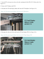
Disk Shelf Power Cable (AW-000957-01/02)
Disk Shelf SCSI Data Cable (AW-000969-01/02)
CPU Backplane Power Cable (AW-000958)
PCI Backplane Power Cable (AW-000964)
Suitcase Power Cable (AW-000956)
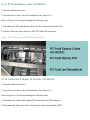
SCSI Data Cable - PCI Bridge Card/PCI Backplane (AW-000954)
Cable - PCI Backplane/PCI Fault Display PCB (AW-001113)
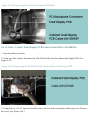
PCI Fault Display Cable (AW-000982)
Cabinet Fault Display PCB Cable (AW-000959)
Cable - Cabinet Fault Display PCB/Cabinet Fault LEDs (AW-000985)
Suitcase LED Board
U450 16-port Support Bracket
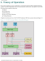
5. Theory of Operation
Suitcase
CPU-Memory Board
PA-8500 Processor
file:///H|/CSDoc/leotsg/toc.html (3 of 5) [01/12/2000 11:50:18 AM]
TOC
Memory Module
Console Controller Module
Cooling Fans
Power Supply
PCI Subsystem
PCI Bus
PCI Bridge Card
Flash card
PCI Adapter Cards
PCI Subsystem Cooling
Disk Subsystem
Input DC Power
Disk Enclosure Components
Disk Configurations
Disk Subsystem Cooling
Disk Subsystem Cabling
Power and Control Subsystem
Power Tray 1
Power Tray 2
Power Specifications
Cooling Subsystem
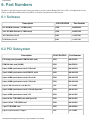
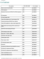
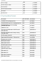
6. Part Numbers
Suitcase
PCI Subsystem
Power Subsystem
Cabinet
Tape Drives/Modem /Terminals
Optional Equipment
file:///H|/CSDoc/leotsg/toc.html (4 of 5) [01/12/2000 11:50:18 AM]
TOC
7. Related Documentation
Customer Service Documentatiion on the WWW
Customer Documentation
Engineering Documentation
Sales/Marketing Documentation on the WWW
file:///H|/CSDoc/leotsg/toc.html (5 of 5) [01/12/2000 11:50:18 AM]
Introduction
1. Introduction
This section describes the requirements, components, configurations, and upgrade options for Stratus PA-8500 Continuum Series
400 systems. It covers the following topics:
● Overview
● Operating system requirements
● Hardware components
● System configurations
● System specifications
1.1 Overview
PA-8500 Continuum Series 400 systems combine the Hewlett Packard PA-RISC PA-8500 microprocessor with Stratus
continuously available hardware. The microprocessor is available in uni or twin processor designs running at 360 MHz with 1.5
MB of L1 on-chip memory cache. The I/O section is based on the PCI (Peripheral Component Interconnect) I/O bus and uses
standard commodity PCI cards.
The system is available in AC only. Both domestic and international versions are available, each with appropriate input voltage
ranges.
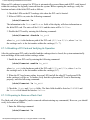
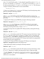
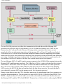
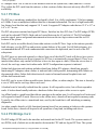
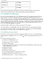
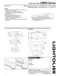
Figure 1-1shows a typical system.
Figure 1-1. PA-8500 Continuum Series 400 System
1.2 Operating System Requirements
PA-8500 Continuum Series 400 systems are currently supported only by HP-UX (Minimum Release 11.00.01)
file:///H|/CSDoc/leotsg/section1.html (1 of 6) [01/12/2000 11:50:21 AM]
Introduction
All software is source-code compatible with Continuum 600/1200 Series systems.
1.3 Hardware Components
The PA-8500 Continuum Series 400 system cabinet houses the following major assemblies in a tower arrangement:
● Suitcases (2)
● PCI subsystem
● Disk subsystem
● Power and control subsystem
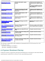
An amber LED, labeled CABINET FAULT, is located at the top of the cabinet, front and rear. The system can accommodate
either overhead or under-the-floor cabling. The top of the cabinet is an open rectangle that serves as the cable port. This opening
also plays a significant role in cooling the system. The system base has a perforated cover to accommodate system cabling that
comes from under the floor.
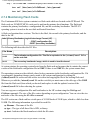
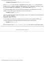
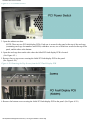
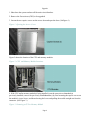
A card labeled STATUS LIGHTS - CRU LEDS is attached to the backplane access cover on the front of the cabinet. The card
summarizes the meaning of status-LED states for the power supplies, alarm control units (ACUs), disk drives, and suitcases.
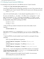
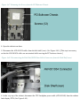
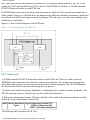
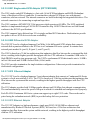
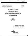
Figure 1-2 shows the components that are accessible from the front of the system cabinet. For a detailed description of system
LEDs, refer to Section 3.
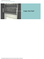
Figure 1-2. PA-8500 Continuum Series 400 System Components (Front)
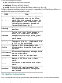
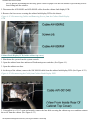
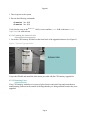
Another card labeled STATUS LIGHTS - CRU LEDS is located on the rear of the cabinet on the suitcase backplane cover. It
summarizes the meaning of the PCI-card status-LED states.
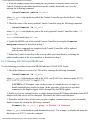
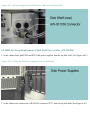
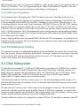
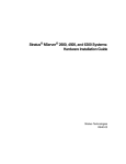
Figure 1-3 shows the components that are accessible from the rear of the cabinet. For a detailed description of system LEDs, refer
to Section 3.
Figure 1-3. PA-8500 Continuum Series 400 System Components (Rear)
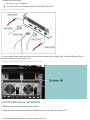
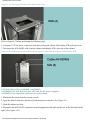
1.3.1 Suitcases
The two PA-8500 suitcases are identical. Each houses the following components:
● CPU-Memory motherboard (contains one or two CPU/cache modules, one to four memory modules, and the Console
Controller module)
● Power supply
● Two cooling fans
For a detailed description of the suitcases, refer to Section 5.1.
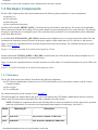
The following table lists model numbers and gives a brief description of the CPU-Memory motherboards (suitcases), memory
module, and CPU/cache module supported in PA-8500 Continuum Series 400 systems.
NOTE: The hardware components shown in the following table are at the base minimum revisions approved for operation
at the time of publication. For current revision requirements and complete revision history, refer to the ??.
Model
Marketing ID
Description
G262
P1874H-ST
Uni processor, 360 MHz, 1.5 MB cache
G272
P1884H-ST
Twin processor, 360 MHz, 2\1.5 MB cache
file:///H|/CSDoc/leotsg/section1.html (2 of 6) [01/12/2000 11:50:21 AM]
Introduction
M715
M715-2
Memory module (0.5 GB)
M717
M717-2
Memory module (2 GB)
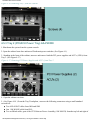
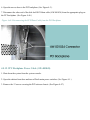
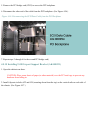
1.3.2 PCI Subsystem
The PCI subsystem consists of the following major components:
● PCI bus
● Two PCI card cages
● PCI bridge cards (one per card cage)
● PCI adapter cards (up to 14)
For a detailed description of the PCI subsystem and its functions, refer to Section 5.2.
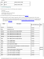
The following table lists the PCI adapters supported by HP-UX 11.00.01 on PA-8500 Continuum Series 400 systems.
Note: The PCI cards shown in the following table are based on information available at the time of publication. For
current (and more detailed) PCI information refer to the PCI/PMC Adapter Technical Reference. The document is
also available in PDF format.
Model
Description
Min. HP-UX Release
Notes
K138-10
PCI bridge card
11.00.01
E525
PCMCIA flash card
11.00.01
U403-01
4-port, 4-MB synchronous adapter (EIA530)
11.00.01
U403-02
4-port, 4-MB synchronous adapter (V.36)
11.00.01
U403-03
4-port, 4-MB synchronous adapter (X.21)
11.00.01
U403-04
4-port, 4-MB synchronous adapter (V.35)
11.00.01
U404
8-port 4-MB synchronous adapter (RS-232)
11.00.01
U420
1-port T1/ISDN adapter
11.00.01
U420E
1-port E1/ISDN adapter
11.00.01
U450
8-port asynchronous adapter
11.00.01
U501
Fast wide single-ended SCSI adapter (1 external/2 internal ports)
11.00.01
U502
Differential SCSI adapter
Post GA
U503
Differential SCSI adapter for EMC Symmetrix
Post GA
U512
2-port ethernet adapter (10/100 Mbps)
11.00.01
U513
1-port ethernet adapter (10/100 Mbps)
11.00.01
U520
1-port token ring adapter (4/16 Mbps)
11.00.01
file:///H|/CSDoc/leotsg/section1.html (3 of 6) [01/12/2000 11:50:21 AM]
Introduction
U530
FDDI adapter
11.00.01
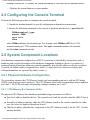
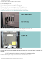
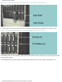
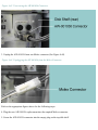
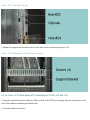
1.3.3 Disk/Tape Subsystem
The disk subsystem consists of two highly integrated, modular disk enclosures, each of which houses up to seven 3.5" SCSI disk
drives. The drives are duplexed (top to bottom) for fault tolerance. Each disk enclosure can also house two power supply
modules, three cooling fans, an SES (SCSI Enclosure Services) module, a SE-SE (single-ended to single-ended) I/O repeater
module, and a terminator module. The seven disks and two power supplies are front mounted; all other modules plug in from the
rear.
For a detailed description of the disk subsystem, refer to Section 5.3.
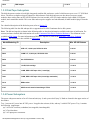
The following table lists the disk and tape drives supported on PA-8500 Continuum Series 400 systems..
Note: The disk and tape drives shown in the following table are based on information available at the time of publication. For
current (and more detailed) disk information refer to the Continuum Disk Drives Technical Reference. The document is also
available in PDF format. For more information on DDS DAT tape drives, refer to the DDS DAT Tape Drive Technical
Reference. The document is also available in PDF format.
Model/Marketing ID
Description
Min. HP-UX Release
D841
9-GB 3.5", 10,000 rpm, SCSI disk drive
11.00.01
D842
18-GB 3.5", 10,000 rpm, SCSI disk drive
11.00.01
D859
40x CD-ROM drive
11.00.01
T804
1.2-GB, QIC cartridge
11.00.01
T805
12-GB, DDS-3 DAT tape drive (1 cartridge)
11.00.01
T806
72-GB, DDS-3 DAT tape drive (6-cartridge autoloader)
11.00.01
C419
RSN modem
11.00.01
V105
ASCII console terminal emulating a VT320
11.00.01
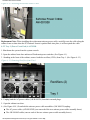
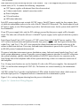
1.3.4 Power Subsystem
The power subsystem consists of an AC front end unit (tray 1) and a power shelf (tray 2). Both are located in the upper section of
the cabinet.
Tray 1 converts AC power into 48 VDC power. It supplies the suitcases, disks, and tray 2 with 48 VDC power. Tray 1 contains
the following components:
● 2 AC-to-DC rectifiers (redundant, hot swappable, interchangable)
● 2 Circuit breakers
● 2 AC input power connectors
file:///H|/CSDoc/leotsg/section1.html (4 of 6) [01/12/2000 11:50:21 AM]
Introduction
●
Backplane
Tray 2 supplies the power for the alarm control unit and PCI cards. It contains the following components:
● Interface backplane
● 2 PCI power supplies with internal fans (forced convection)
● 2 Alarm control units (ACUs)
● 2 Circuit breakers
For a detailed description of the power and control subsystem, refer to Section 5.4.
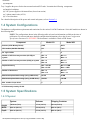
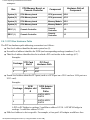
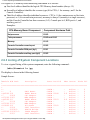
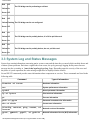
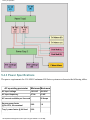
1.4 System Configurations
The hardware configuration requirements and restrictions for the various PA-8500 Continuum Series 400 models are shown in
the following table.
NOTE: The configurations shown in the following table are based on information available at the time of
publication. For current (and more detailed) configuration information refer to the Stratus Configuration
Specification Document No. XXXXXX. The document is available in Word or PDF format.
Component
Model 419
Model 429
Suitcase (CPU-Memory Board)
G262
G272
CPU module (360 MHz PA-8500)
Uni
Twin
No. logical CPUs
1
2
Number of M715 memory modules (0.5 GB) per
system
Min. = 2
Max. = 8
Min. = 2
Max. = 8
Number of M717 memory modules (2 GB) per system
Min. = 2
Max. = 8
Min. = 2
Max. = 8
Duplexed memory
Min. = 0.5 GB
Max. = 4 GB*
Min. = 0.5 GB
Max. = 4 GB*
Number of disk drives
Min. = 2
Max. = 14
Min. = 2
Max. = 14
Maximum duplexed disk storage (using 9-GB drives)
63 GB
63 GB
Maximum duplexed disk storage (using 18-GB drives)
126 GB
126 GB
Max. number of tape drives
4
4
* 3.75 GB actually used by HP-UX.
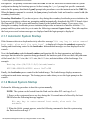
1.5 System Specifications
1.5.1 Physical
System
Suitcase
Shipping Container
Height
182.9 cm (72 in)
47 cm (18.5 in)
202 cm (79.5 in)
Width
60.0 cm (23.6 in)
22 cm (8.5 in)
86.4 cm (34 in)
Depth
60.0 cm (23.6 in)
47 cm (18.5 in)
96.5 cm (38 in)
file:///H|/CSDoc/leotsg/section1.html (5 of 6) [01/12/2000 11:50:21 AM]
Introduction
Weight
318.2 kg (701 lb) max. configuration 28.8 kg (63.5 lb)
34 kg (75 lb)
Minimum 0.6 m (2 ft) in front and
rear of cabinet.
Service
Minimum 0.5 m (1.5 ft) of
Clearance unobstructed area above the cable
trough on top of cabinet.
1.5.2 Environmental
Operating Temperature:
-200 to 6000 ft
4.5º to 40º C (40º to 104º F)
6000 to 8000 ft
4.5º to 35º C (40º to 95º F)
8000 to 10,000 ft
4.5º to 30º C (40º to 86ºF)
Max. rate of temp. change:
12º/hr C (21.6 º/hr F)
Relative humidity:
10% to 80% non-condensing
Maximum heat dissipation:
9200 Btu/hr (2700 W)
Electrostatic Discharge:
Air discharge:
8 kv (max)
Direct-contact discharge
6 kv (max)
Dust:
To prevent dust buildup, operate system where minimal dust
is generated. Use of air filters throughout the system is also
an option.
Acoustical Noise:
Normal Conditions
55 dbA (max)
High temperature or fault condition
61 dbA (max)
1.5.3 Electrical
Minimum
AC input voltage
AC input frequency
AC current available per line cord
Source power factor
@ Po>25%, Vin=nominal
Steady state:
AC input KVA
AC input Watts
Maximum
180 VAC
264 VAC
47 Hz
63 HZ
20 Amps
0.80
1.0
N/A
2.4 KVA
2200 Watts
file:///H|/CSDoc/leotsg/section1.html (6 of 6) [01/12/2000 11:50:21 AM]
11.00.01 Operating and Maintenance Procedures
2. Operating and Maintenance
Procedures
This chapter explains the basic operating procedures used for PA-8500 Continuum 400 Series system
operation and maintenance under the HP-UX 11.00.01 operating system. Topics covered include the
following:
● Starting the system
● Shutting down the system
● Rebooting the system
● Configuring the console terminal
● Console command menu
● System component locations
● Maintenance procedures
For a more complete description of the procedures covered in this section refer to the manual HP-UX
Operating System: Fault Tolerant System Administration (R1004H-04-ST).
There is no physical control panel on Continuum 400 Series systems. Operating commands are entered at
the system console which is connected to the system via the Console Controller module in the suitcase.
2.1 Starting the System
When the system is powered up, it displays the model, memory size, board revision, and other
information. It then displays the following message on the system console and waits approximately 10
seconds before proceeding with an automatic boot process in order to provide the option of performing a
manual boot:
Hit any key to enter manual boot mode, else wait for auto boot.
The bootstrap process begins upon completion of system power up (and at certain other times, such as
after a reset_bus console command).
Boot Start Up - After the processor is RESET, CPU PROM (the Stratus PROM code firmware)
performs a self-test and initializes the processor. If autoboot is enabled on the system, CPU PROM
loads and transfers control to lynx (the Stratus HP-UX primary bootloader), which loads and transfers
control to isl (the secondary bootloader). If autoboot is not enabled, CPU PROM provides an interactive
interface with the PROM: prompt and the system waits for you to enter the following command: boot
location where location is the location of the boot device (flash card). When the boot command
is executed, the CPU PROM loads and transfers control to lynx (the Stratus HP-UX primary
bootloader).
Primary Bootloader - The lynx primary bootloader provides an interactive interface with the lynx$
prompt and the system waits for you to enter the following command: boot [options] where options are
file:///H|/CSDoc/leotsg/section2.html (1 of 30) [01/12/2000 11:50:31 AM]
11.00.01 Operating and Maintenance Procedures
not required. The primary bootloader reads the CONF file on the flash card for instructions on system
configuration during the bootstrap process before issuing the lynx$ prompt, but specific commands
entered at the primary bootloader lynx$ prompt take precedence over the instructions in the CONF file.
When the boot command is executed, the lynx primary bootloader loads and transfers control to isl (the
secondary bootloader).
Secondary Bootloader - If you do not press a key during the secondary bootloader process initiation, the
boot process continues without any prompting and isl automatically downloads the HP-UX kernel object
file from an HP-UX file system and transfers control to the loaded kernel image. If you press a key
during the secondary bootloader process initiation, isl provides an interactive interface with the ISL>
prompt and the system waits for you to enter the following command: hpux boot. Then, isl completes
the boot process and various messages are displayed until the login prompt is displayed.
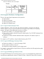
2.1.1 Automatic System Startup
If the firmware detects no keyboard activity after the message 'Hit any key to enter manual
boot mode, else wait for auto boot' is displayed, it begins the autoboot sequence by
loading and transferring control to the bootloader. Informational messages are then displayed on the
console.
Next, the bootloader reads the bootloader configuration file for boot parameters and displays
messages that describe the operation being performed, the hardware path of the root disk, the path name
of the kernel, the TEXT size, the DATA size, the BSS size, and start address of the load image. For
example:
Booting disc(14/0/0.0.0;0)/stand/vmunix
4233148+409600+465536 start 0x27of68
Finally, the bootloader passes control to the loaded image. The loaded image displays numerous
configuration and status messages. The bootup process ends when you see the login prompt on the
console.
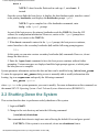
2.1.2 Manual System Startup
Perform the following procedure to boot the system manually.
NOTE: The system can be booted from the flash card in either PCI card cage 2 or 3.
1. Power on the system and press any key during the 10-second interval allowed by the boot
PROM when the following message appears:
Hit any key to enter manual boot mode, else wait for
autoboot
2. When the PROM: prompt appears, enter the following command to boot the system using
the flash card in card cage 2.
file:///H|/CSDoc/leotsg/section2.html (2 of 30) [01/12/2000 11:50:31 AM]
11.00.01 Operating and Maintenance Procedures
boot 2
NOTE: To boot from the flash card in card cage 3, enter boot 3
instead.
Once the system finds the boot device, it displays the boot hardware path, transfers control
to the primary bootloader, and displays the bootloader prompt lynx$.
NOTE: To get a complete list of the bootloader commands, enter
help at the lynx$ prompt.
As part of the boot process, the primary bootloader reads the CONF file (from the LIF
volume) for configuration information However, entries at the lynx$ prompt have
precedence over entries in the CONF file.
3. When boot command is entered at the lynx$ prompt, the boot process continues,
control transfers to the secondary bootloader (isl) and the following prompt appears:
ISL>
At this point you can enter various secondary bootloader (isl) commands. However, do not
change the boot device.
5. Enter the hpux boot command to have the boot process continue without further
prompting. Various messages are displayed until the login prompt appears, at which point
the boot process is complete.
System parameter information such as the date and time can be modified using /sbin/set_parms.
To enter the appropriate set_parms dialog screen to manually add or modify information after
booting, log in as superuser and specify the following command:
set_parms option
where option is the system parameter you want to modify. For more information on this command, see
the manual HP-UX Operating System: Fault Tolerant System Administration (R1004H-03).
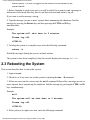
2.2 Shutting Down the System
This section describes how to perform an orderly shutdown of the system.
1. Login as root.
2. Change to the root directory and enter the following command:
/usr/sbin/shutdown
This command shuts down to single-user state allowing the default 60 second grace period.
CAUTION: If the system is on a network, do not run shutdown from a
file:///H|/CSDoc/leotsg/section2.html (3 of 30) [01/12/2000 11:50:31 AM]
11.00.01 Operating and Maintenance Procedures
remote system. You will be logged out and control will be returned to the
system console.
3. Before changing to single-user state, you will be asked if you want to send a message to
inform users how much time they have to end their activities and when to log off.
If you want to send a message, enter y.
4. Type the message (on one or more separate lines) announcing the shutdown. End the
message by pressing the Return key and then pressing the CTRL and D keys
simultaneously.
Example:
The system will shut down in 5 minutes.
Please log off.
<CTRL-D>
5. To bring the system to a complete stop, enter the following command:
reboot -h
Watch the messages during the process and note actions.
The system is shut down completely when the console displays the message halted.
2.3 Rebooting the System
This section describes how to reboot the system.
1. Login as root.
2. Check to see if any users are on the system by entering the who -H command.
3. If there are users on the system, enter the wall command followed by a message (on one or
more separate lines) announcing the shutdown. End the message by pressing the CTRL and D
keys simultaneously.
Example:
wall
The system will be shut down in 5 minutes.
Please log off.
<CTRL-D>
4. If the system is in single-user state, enter the following command:
file:///H|/CSDoc/leotsg/section2.html (4 of 30) [01/12/2000 11:50:31 AM]
11.00.01 Operating and Maintenance Procedures
reboot
Otherwise, enter the following:
shutdown -r
2.4 Console Command Menu
The Console Controller supports a command menu that can be used to issue key machine management
commands to the system from the system console. It can reboot or execute other commands on a
nonfunctioning system.
To access the console command menu from a V105 console using an ANSI keyboard, press the F5 key.
To access the console command menu from a V105 using a PC keyboard, press the CTRL and PAUSE
keys simultaneously. Other terminals generally use the Break key alone to enter command mode. This
puts the console into command mode and displays the following menu:
help...........displays command list.
shutdown.......begin orderly system shutdown.
restart_cpu....force CPU into kernel dump/debug mode.
reset_bus......send reset to system.
hpmc_reset.....send HPMC to cpus.
history........display switch closure history.
quit, q........exit the front panel command loop.
. ............display firmware version.
The following describes the actions of each command:
help - Displays the menu list on the screen.
shutdown - Initiates an immediate orderly system shutdown.
restart_cpu - Issues a broadcast interrupt (level 7) to all CPU boards in the system. Generates
a system dump.
reset_bus - If there is a nonbroken CPU/memory board in the system, this command issues a
"warm" reset (that is, save current registers) to all boards on the main system bus. Immediately
kills all system activities and reboots the system. CAUTION: Do not use this command on
PA-8500 systems if you want a system dump; use the hpmc_reset command instead.
hpmc_reset - Issues a high priority machine check (HPMC) to all CPUs on all CPU-memory
boards in the system. This command first flushes the caches to preserve dump information and
then (based on an internal flag value) either invokes a "warm" reset (that is, reboots the system,
saving current memory and registers) or simply returns to the HP-UX operating system.
history - Displays a list of the most recently entered console commands.
quit, q - Exits the console command menu and returns the console to its normal mode. (If
file:///H|/CSDoc/leotsg/section2.html (5 of 30) [01/12/2000 11:50:31 AM]
11.00.01 Operating and Maintenance Procedures
nothing is entered for 20 seconds, the system automatically exits the console command menu.)
. - Displays the current firmware version number.
2.5 Configuring the Console Terminal
Perform the following procedure to configure the console terminal.
1. Consult the terminal manual for specific configuration information or instructions.
2. Execute the following commands at the console or put them into the root /.profile file.
TERM=terminal_type
export TERM
tput init
tabs
where TERM establishes the terminal type. For example, enter TERM=vt320 for a V105
terminal running in VT320 emulation mode. The tput command initializes the terminal,
and the tabs command sets tabs.
2.6 System Component Locations
Each hardware component configured on a HP-UX system can be identified by its hardware path. A
hardware path specifies the address of the hardware components leading to a device. It consists of a
numerical string of hardware addresses, notated sequentially from the bus address to the device address.
Typically, the initial number is appended by a slash (/) to represent a bus converter or adapter and
subsequent numbers are separated by slashes or dots (.).
2.6.1 Physical Hardware Configuration
The system bus connects the CPU-Memory boards (and corresponding suitcases) with the PCI bridge
(PCIB) cards (and associated cardcages). The CPU-Memory board (and corresponding suitcase) numbers
are 0 and 1. The PCIB card (and corresponding cardcage) numbers are 2 and 3.
2.6.1.1 CPU-Memory Bus Hardware Paths
The physical CPU-Memory board hardware path addressing convention is as follows:
● First-level address identifies the bus. The system bus is 0 and the console controller (RECC) bus is
1.
● Second-level address identifies either the CPU-Memory board or the console controller. In either
case, the values for duplexed boards are 0 and 1.
● Third-level address identifies the component on the CPU-Memory board (0 for the CPU, 1 for the
memory module)
file:///H|/CSDoc/leotsg/section2.html (6 of 30) [01/12/2000 11:50:31 AM]
11.00.01 Operating and Maintenance Procedures
Examples:
CPU-Memory Board or
Console Controller
Bus
Hardware Path of
Component
Component
System (0)
CPU-Memory board
CPU (processor) 0/0/0
System (0)
CPU-Memory board
CPU (processor) 0/1/0
System (0)
CPU-Memory board
Memory Module
0/0/1
System (0)
CPU-Memory board
Memory Module
0/1/1
RECC (1)
Console Controller
Console
Controller
1/0
RECC (1)
Console Controller
Console
Controller
1/1
2.6.1.2 PCI Bus Hardware Paths
The PCI bus hardware path addressing convention is as follows:
● First-level address identifies the main system bus (0).
● Second-level address identifies the PCIB (and corresponding cardcage) numbers (2 or 3).
● Third-level address identifies the slot in which a PCI card resides in the cardcage (0-7).
Examples:
●
Cardcage
PCI Card
Slot #
PCI Card
Hardware Path
2
0-7
0/2/7
3
0-7
0/3/7
Fourth-level address identifies PCI ports (such as a SCSI port on a U501 card or a LAN port on a
U513 card).
Examples:
SCSI
Cardcage Adapter slot
#
●
SCSI Adapter
Hardware
Paths
2
7
0/2/7/0, 0/2/7/1,
0/2/7/2
3
7
0/3/7/0, 0/3/7/1,
0/3/7/2
A PCI-to-PCI bridge in cardcage 2 could have address 0/2/3/0. A PCMCIA bridge in
cardcage 3 could have address 0/3/0/0.
Fifth-level address is device specific. For example, a four-port LAN adapter would have four
file:///H|/CSDoc/leotsg/section2.html (7 of 30) [01/12/2000 11:50:31 AM]
11.00.01 Operating and Maintenance Procedures
fifth-level addresses, one for each port.
Example:
LAN
Cardcage Adapter Slot
#
2
3
LAN Adapter
Hardware
Paths
0/2/3/0/4,
0/2/3/0/5,
0/2/3/0/6, 0/2/3/0/7
2.6.2 Logical Hardware Configuration
There are four major logical components on the system bus:
● Logical cabinet
● Logical LAN manager
● Logical SCSI manager (LSM)
● Logical CPU-Memory board.
2.6.2.1 Logical Cabinet Hardware Path
Cabinet components—such as ACU units, fans, and power supplies—do not have true physical
addresses. However, they are treated as pseudo devices and given logical addresses for reporting
purposes. The logical cabinet addressing convention is as follows:
● The first-level address, 12, is the logical cabinet (CAB).
● The second-level address identifies the specific cabinet number. For a PA-8500 Continuum Series
400, this is always 0.
● The third-level address identifies individual cabinet components. (The number sequence is
arbitrary.)
For example, an ACU could have a logical cabinet hardware path of 12/0/1.
2.6.2.2 Logical LAN Manager Hardware Paths
●
●
●
The first-level address, 13, is the LAN manager (LNM).
The second-level address is always 0.
The third-level address identifies a specific adapter (port).
For example, a system with three logical ethernet (LAN) ports would have the following hardware paths:
13/0/0, 13/0/1, and 13/0/2.
2.6.2.3 Logical SCSI Manager Hardware Paths
The logical SCSI manager has two primary purposes: to serve as a generalized host bus adapter driver
front-end and to implement the concept of a logical SCSI bus. A logical SCSI bus (LSB) is one that is
file:///H|/CSDoc/leotsg/section2.html (8 of 30) [01/12/2000 11:50:31 AM]
11.00.01 Operating and Maintenance Procedures
mapped independently from the actual hardware addresses. A physical SCSI bus can have one or two
initiators located anywhere in the system, but the logical SCSI manager allows you to target each SCSI
bus by its logical SCSI address without regard to its physical location. By using a logical SCSI manager,
you can configure (and reconfigure) dual-initiated SCSI buses across any SCSI controllers in the system.
The LSM also provides transparent failover between partnered physical controllers (which are connected
in a dual-initiated mode).
The LSM addressing convention is as follows:
● First-level address identifies the LSM number (always 14).
● Second-level address describes a transparent slot (always 0).
● Third-level address is the LSB number (0-15).
● Fourth-level address is the bus address associated with the device (0-5, 14). This is the SCSI target
ID.
● Fifth-level address is the logical unit number (LUN) of the device (always 0).
Examples for disk drives:
NOTE: The 7th drive slot in the enclosure is labeled 14, since 14 is the SCSI ID of that
drive.
LSB Disk Drive Slot #s in Disk Enclosure
Disk Drive LSM Hardware Paths
0
0, 1, 2, 3, 4, 5, 14
14/0/0.0.0, 14/0/0.1.0, 14/0/0.2.0, 14/0/0.3.0,
14/0/0.4.0, 14/0/0.5.0, 14/0/0.14.0
1
0, 1, 2, 3, 4, 5, 14
14/0/1.0.0, 14/0/1.1.0, 14/0/1.2.0, 14/0/1.3.0,
14/0/1.4.0, 14/0/1.5.0, 14/0/1.14.0
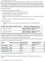
Four LSBs are defined off the U501 SCSI controllers: dual-initiator buses 0 and 1 for disk drives and
single-initiator buses 2 and 3 for tape/CD-ROM drives. Dual-initiator buses are connected to two SCSI
controllers (primary and secondary) to provide fault-tolerant protection.
The following table shows the LSM hardware paths and SCSI primary/secondary controller hardware
paths that are associated with each of the four LSBs.
LSB #
LSM Hardware Path
Active SCSI Port
Hardware Path
Standby SCSI Port
Hardware Path
0 (dual-initiator)
14/0/0
0/2/7/1
0/3/7/1
1 (dual-initiator)
14/0/1
0/2/7/2
0/3/7/2
2 (single-initiator) 14/0/2
0/2/7/0
none
3 (single-initiator) 14/0/3
0/3/7/0
none
2.6.2.4 Logical CPU-Memory Board Addresses
The logical CPU-Memory board is an abstraction of the physical CPU-Memory board addressing
scheme.
file:///H|/CSDoc/leotsg/section2.html (9 of 30) [01/12/2000 11:50:31 AM]
11.00.01 Operating and Maintenance Procedures
The logical CPU-Memory board addressing convention is as follows:
● First-level address identifies the logical CPU-Memory board number (always 15).
● Second-level address identifies the resource type (0 for CPUs, 1 for memory, and 2 for the
Console Controller).
● Third-level address identifies individual resources: CPU is 0 (for a uniprocessor or first twin
processor) or 1 (for second twin processor), memory is always 0 (memory is a single resource),
and the Console Controller has three resources (0-2): Console port is 0, RSN port is 1, and
auxiliary port is 2.
Examples:
CPU-Memory Board Component
Component Hardware Path
Uniprocessor
15/0/0
Twin processors
15/0/0 and 15/0/1
Memory
15/1/0
Console Controller console port
15/2/0
Console Controller RSN port (tty1)
15/2/1
Console Controller auxiliary port (tty2)
15/2/2
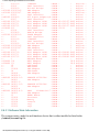
2.6.3 Listing of System Component Locations
To view a typical listing of the system components, enter the following command:
/sbin/ftsmaint ls |pg
The display is shown in the following format.
Sample Screen:
>Modelx H/W Path
Description
State Serial#
PRev Status
FCode FCT
>
>================================================================================
>
>CLAIM Online 0
>0
GBUS Nexus
CLAIM Online 0
>g26200 0/0
PMERC Nexus
CLAIM 10300
9.0 Online 5
>0/0/0
CPU Adapter
CLAIM Online 0
>m71500 0/0/1
MEM Adapter
CLAIM Online 0
>g26200 0/1
PMERC Nexus
CLAIM 10323
9.0 Online 0
>0/1/0
CPU Adapter
CLAIM Online 0
>m71500 0/1/1
MEM Adapter
CLAIM Online 0
>k13800 0/2
PCI Nexus
CLAIM 12091
Online 1
>0/2/0
SLOT Interface
CLAIM Online 0
>0/2/0/0
PCMCIA Bridge
CLAIM Online 0
>e52500 0/2/0/0.0
FLASH Adapter
CLAIM Online 0
>0/2/1
SLOT Interface
CLAIM Online 0
file:///H|/CSDoc/leotsg/section2.html (10 of 30) [01/12/2000 11:50:31 AM]
11.00.01 Operating and Maintenance Procedures
>>>>u51200
>u51200
>>u40300
>>u50100
>u50100
>u50100
>k13800
>>>e52500
>>>>>u51200
>u51200
>>u50100
>u50100
>u50100
>>e59400
>e59400
>>>>>>>d84100
>>>d84100
>>>d85900
>>>:
>>>>-
0/2/1/0
0/2/2
0/2/2/0
0/2/2/0/6
0/2/2/0/7
0/2/3
0/2/6/0
0/2/7
0/2/7/0
0/2/7/1
0/2/7/2
0/3
0/3/0
0/3/0/0
0/3/0/0.0
0/3/1
0/3/1/0
0/3/2
0/3/2/0
0/3/2/0/6
0/3/2/0/7
0/3/5
0/3/7/0
0/3/7/1
0/3/7/2
1
1/0
1/1
12
13
13/0/0
14
14/0/0
14/0/0.0
14/0/0.0.0
14/0/1
14/0/1.0
14/0/1.0.0
14/0/2
14/0/2.4
14/0/2.4.0
14/0/3
15
15/0/0
15/1/0
15/2/0
15/2/1
15/2/2
11ABF002
SLOT Interface
PCI-PCI Bridge
LAN Adapter
LAN Adapter
SLOT Interface
X25 4-port Adapter(4
SLOT Interface
SCSI Adapter W/SE
SCSI Adapter W/SE
SCSI Adapter W/SE
PCI Nexus
SLOT Interface
PCMCIA Bridge
FLASH Adapter
SLOT Interface
11ABF002
SLOT Interface
PCI-PCI Bridge
LAN Adapter
LAN Adapter
SLOT Interface
SCSI Adapter W/SE
SCSI Adapter W/SE
SCSI Adapter W/SE
RECCBUS Nexus
RECC Adapter
RECC Adapter
CAB Nexus
LNM Nexus
LAN Adapter
LSM Nexus
LSM Adapter
UNCLA
CLAIM
CLAIM
CLAIM
CLAIM
CLAIM
CLAIM
CLAIM
CLAIM
CLAIM
CLAIM
CLAIM
CLAIM
CLAIM
CLAIM
CLAIM
UNCLA
CLAIM
CLAIM
CLAIM
CLAIM
CLAIM
CLAIM
CLAIM
CLAIM
CLAIM
CLAIM
CLAIM
CLAIM
CLAIM
CLAIM
CLAIM
CLAIM
CLAIM
SEAGATE ST39103LC
CLAIM
LSM Adapter
CLAIM
CLAIM
SEAGATE ST39103LC
CLAIM
LSM Adapter
CLAIM
CLAIM
SONY
CD-ROM CDU-7 CLAIM
LSM Adapter
CLAIM
LMERC Nexus
CLAIM
Processor
CLAIM
Memory
CLAIM
console
CLAIM
tty1
CLAIM
tty2
CLAIM
42-012157
42-012157
42-012157
12129
42-012081
42-012081
42-012081
-
1
1
0ST5
0ST5
0ST5
1
1
0ST5
0ST5
0ST5
18.0
18.0
0
-
Offline
Online
Online
Offline
Offline
Online
Online
Online
Online
Online
Online
Online
Online
Online
Online
Online
Offline
Online
Online
Offline
Offline
Online
Online
Online
Online
Online
Online
Online
Online
Online
Online
Online
Online
Online
Online
Online
Online
Online
Online
Online
Online
Online
Online
Online
Online
Online
Online
Online
2.6.3.1 Software State Information
The system creates a node for each hardware device that is either installed or listed in the
/stand/ioconfig file.
file:///H|/CSDoc/leotsg/section2.html (11 of 30) [01/12/2000 11:50:31 AM]
-
0
0
0
0
0
0
0
0
0
0
0
1
0
0
0
0
0
0
0
0
0
0
0
0
0
0
0
0
0
0
0
0
0
0
0
0
0
0
0
0
0
0
0
0
0
0
0
0
11.00.01 Operating and Maintenance Procedures
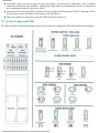
The State field in the ftsmaint ls display can show a hardware component to be in any one of
the software states shown in the following table.
State
Meaning
UNCLAIMED Initialization state, or hardware exists, and no software is associated with the node.
CLAIMED
The driver recognizes the device.
ERROR
The device is recognized, but it is in an error state.
NO_HW
The device at this hardware path is no longer responding.
SCAN
Transitional state that indicates the device is locked. A device is temporarily put in the SCAN state
when it is being scanned by the ioscan or ftsmaint utilities.
The software state of a hardware component can change. For example, a component is initially created in
the UNCLAIMED state when it is detected at boot time. The component moves to the CLAIMED state
when it is recognized and claimed by the appropriate driver. The transitions between the various software
states are controlled by the ioscan and ftsmaint utilities.
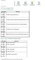
2.6.3.2 Hardware Status Information
In addition to a software state, each hardware component has a particular hardware status. The Status
field in the ftsmaint ls display can have any of the values shown in the following table.
Status
Meaning
Online
The device is actively working.
Online Standby
The device is not logically active, but it is operational. Using the ftsmaint switch or
ftsmaint sync command can be used to change the device status to Online.
Duplexed
The status is appended to the Online status to indicate that the device is fully duplexed.
Duplexing
The status is appended to the Claimed Online or Claimed Offline status to
indicate that the device is in the process of duplexing. This transient status is displayed
after the ftsmaint sync or ftsmaint enable command has been used on the
CPU-Memory board.
Offline
The device is not functional or not being used.
Burning PROM
The ftsmaint burnprom command is in progress on the device. The suitcase stays in
Offline Standby offline standby when burning PROM.
The status of a hardware component can change. For example, a component could go from Online to
Offline because of a hardware or software error.
file:///H|/CSDoc/leotsg/section2.html (12 of 30) [01/12/2000 11:50:31 AM]
11.00.01 Operating and Maintenance Procedures
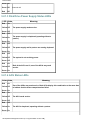
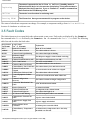
2.6.3.3 Fault Codes
The fault tolerant services return fault codes when certain events occur. Fault codes are displayed by the
ftsmaint ls command in the FCode field and by the ftsmaint ls -l command in the Fault
Code field. The following table lists and describes the fault codes.
ls Format
DSKFAN
Explanation
ls -l Format
Disk Fan Faulted/Missing
The disk fan either faulted or is missing.
HARD
Hard Error
The driver reported a hard error. A hard error
occurs when a hardware fault occurs that the
operating system is unable to correct. Look at
the syslog for related error messages.
HWFLT
Hardware Fault
The hardware device reported a fault. Look at the
syslog for related error messages.
IS
In Service
The CRU/FRU is in service.
MISS
Missing replaceable unit
No hardware was found. The hardware
component has been removed from the system.
Look at the syslog for related error messages.
MTBF
Below MTBF Threshold
The CRU/FRU's rate of transient and hard failures
became too great.
PCIOPN
PCI Card Bay Door Open
The PCI cardcage door is open.
NOPWR
No power
The CRU/FRU lost power.
OVERRD
Cabinet Fan Speed Override Active
The fan override (setting fans to full power from
normal) was activated.
SOFT
Soft Error
The driver reported a transient error. A transient
error occurs when a hardware fault is detected,
but the problem is corrected by the operating
system. Look at the syslog for related error
messages.
USER
User Reported Error
A user issued an ftsmaint disable command
to disable the hardware component.
2.6.4 Hardware Paths and Device Names
Device file names use the following convention:
/dev/type/c#t#d#
file:///H|/CSDoc/leotsg/section2.html (13 of 30) [01/12/2000 11:50:31 AM]
11.00.01 Operating and Maintenance Procedures
type indicates the device type; c#, t#, and d# correspond to the parts of the hardware path as follows:
c# corresponds to the instance number of the SCSI bus on which the disk is connected.
t# corresponds to the SCSI target ID.
d# corresponds to the logical unit number (LUN) - always 0.
Storage devices use the following conventions:
● For disk and CD-ROM devices, type is dsk.
●
●
For tape devices, type is rmt, and the remaining numbers are the same as for disk and CD-ROM
devices. Tape device file names can include additional letters at the end that specify the
operational characteristics of the device. (The /dev/rmt directory also includes standard tape
device files, for example 0m and 0mb, that do not identify a specific device as part of the file
name.)
For flash cards, type is rflash, c# is the instance number of the flash card (either 2 or 3), and
t# and d# are always zero (0). Flash cards also use the form c#a#d# instead of c#t#d#. Flash
cards are not SCSI devices and use physical, not logical, hardware paths.
The following table lists the hardware paths and device names for the disk drives. Disks are numbered
from right to left, as viewed from the front of the system.
NOTE: The 7th drive slot in the enclosure is labeled 14, since 14 is the SCSI ID of that
drive.
Disk
Drive
Slot
Location
Hardware
Path
(Enclosure
0)
0
14/0/0.0.0
/dev/dsk/c0t0d0
14/0/1.0.0
/dev/dsk/c1t0d0
1
14/0/0.1.0
/dev/dsk/c0t1d0
14/0/1.1.0
/dev/dsk/c1t1d0
2
14/0/0.2.0
/dev/dsk/c0t2d0
14/0/1.2.0
/dev/dsk/c1t2d0
3
14/0/0.3.0
/dev/dsk/c0t3d0
14/0/1.3.0
/dev/dsk/c1t3d0
4
14/0/0.4.0
/dev/dsk/c0t4d0
14/0/1.4.0
/dev/dsk/c1t4d0
5
14/0/0.5.0
/dev/dsk/c0t5d0
14/0/1.5.0
/dev/dsk/c1t5d0
14
14/0/0.14.0
/dev/dsk/c0t14d0 14/0/1.14.0
Device Name
(Enclosure 0)
Hardware
Path
(Enclosure
1)
Device Name
(Enclosure 1)
/dev/dsk/c1t14d0
For flash cards, the second-level address in the hardware path (the PCI bus number, either 2 or 3)
corresponds to the c# part of the device name. The other parts of the device name are always 0.
Example:
file:///H|/CSDoc/leotsg/section2.html (14 of 30) [01/12/2000 11:50:31 AM]
11.00.01 Operating and Maintenance Procedures
Cardcage
Flashcard Hardware Path
Device Name
2
0/2/0/0.0
/dev/rflash/c2a0d0
3
0/3/0/0.0
/dev/rflash/c3a0d0
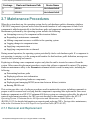
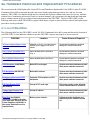
2.7 Maintenance Procedures
When the system boots up, the operating system checks each hardware path to determine whether a
CRU/FRU component is present and to record the model number of each component it finds. Each
component is added automatically to that hardware path, and component maintenance is initiated.
Maintenance performed by the operating system includes the following:
● Attempting recovery if a component suffers transient failures
● Responding to maintenance commands
● Making component resources available to the operating system
● Logging changes in component status
● Supplying component status
● Supplying component state on demand
During normal operation, the operating system periodically checks each hardware path. If a component is
not operating, is missing, or is the wrong model number for that hardware path's definition, messages are
issued to the system log and console.
Replacing or deleting some components requires only that the unit be inserted or removed from the
system. Other removal/replacement procedures require that software commands be entered. The primary
hardware maintenance utility is the ftsmaint command which is used for many tasks, including the
following:
● Determining hardware paths
● Displaying software state information
● Removing and replacing hardware components
● Displaying and managing MTBF (mean time between failures) statistics
● Burning PROM code
This section provides a set of software procedures used to maintain the system, including commands to
prepare a unit for removal and verifying that the component is operating after replacement. Since most
hardware components in a HP-UX Continuum 400 Series system are customer replaceable, the physical
removal/replacement procedures for CRUs are not described in this manual. Refer to the HP-UX
Operating System: Continuum Series 400 Operation and Maintenance Guide Release 1.0
(R025H-01-ST) for detailed information on removing and replacing CRUs. For tape drive maintenance,
refer to the Continuum Series 400 Tape Drive Operation Guide (R719-01-ST).
2.7.1 Removal and Replacement
file:///H|/CSDoc/leotsg/section2.html (15 of 30) [01/12/2000 11:50:32 AM]
11.00.01 Operating and Maintenance Procedures
2.7.1.1 Preparing to Remove a Suitcase
A suitcase is hot pluggable (can be removed without entering any commands) if its red LED is on and the
yellow and green LEDs are off. However, you should verify its location as follows:
1. Note the number (either 0 or 1) on the front label of the failed suitcase.
2. Enter the following command to verify the state and status of the suitcase:
/sbin/ftsmaint ls hw_path
where hw_path is the hardware path of the suitcase (0/0 or 0/1).
The information in the State and Status fields of the display will show information on
the failed suitcase.
2.7.1.2 Verifying Suitcase Operation
After the replacement suitcase is installed, the system automatically tests it and duplexes it with the other
suitcase. When testing is complete, the red LED will turn off and the green LED will illuminate. Perform
the following to verify proper operation of the suitcase:
1. Enter the /sbin/ftsmaint ls hw_path command.
where hw_path is the hardware path of the suitcase (0/0 or 0/1).
2. Verify that the replacement suitcase is now operational by checking the State and Status
fields. While the suitcase is coming online, its state should be listed as Claimed and the status
should be listed as Offline Duplexing. When duplexing is complete, its State field should
be listed as CLAIMED and the Status field should be listed as Online Duplexed.
3. Enter the following command to update the date to ensure that it is the same on both Console
Controllers.
date mmddHHMM[yyyy]
where mm specifies the month, dd is the day of the month, HH is the hour (24-hour system),
MM is the minute, and yyyy is the year.
NOTE: All new or replacement boards come with the latest PROM code
already installed. Therefore, it is not necessary to burn the PROM of any new
hardware. However, if only one suitcase is replaced, it might be necessary to
burn the PROM on the Console Controller in the "old" suitcase to match the
Console Controller in the replacement suitcase. Burning the PROM code on the
Console Controller is described in Section 2.7.3.2.
2.7.1.3 Preparing to Remove a PCI Card
file:///H|/CSDoc/leotsg/section2.html (16 of 30) [01/12/2000 11:50:32 AM]
11.00.01 Operating and Maintenance Procedures
When an I/O cardcage is opened, its PCI bus is automatically powered down and all PCI cards housed
within the cardcage are logically removed from the system. Before opening the cardcage, verify the
location and state of the failed PCI card as follows:
1. Check the LEDs on the PCI cardcage slot where the PCI card is located.
2. If the red LED is on, enter the following command:
/sbin/ftsmaint ls
The information in the State and Status fields of the display will show information on
the failed PCI card. The state will be ERROR and the status will be Offline.
3. Disable the PCI card by entering the following command:
/sbin/ftsmaint disable hw_path
where hw_path is the hardware path of the PCI card. (0/2/x or 0/3/x, where 2 or 3 is
the cardcage and x is the slot number within the cardcage (0-7).
2.7.1.4 Enabling a PCI Card and Verifying its Operation
After the replacement PCI card is installed and the cardcage door is closed, the system automatically
tests and brings all the cards in that cardcage online.
1. Enable the new PCI card by entering the following command:
/sbin/ftsmaint enable hw_path
where hw_path is the hardware path of the PCI card (0/2/x or 0/3/x, where 2 or 3 is
the cardcage and x is the slot number within the cardcage (0-7).
2. When the PCI card comes online, its green LED (and all the other PCI card green LEDs
in the cardcage) will be on. To further verify that the replacement PCI card is functioning
properly, enter the following command:
/sbin/ftsmaint ls hw_path
3. Check the State and Status fields. The State field should be listed as CLAIMED and
the Status field should be listed as Online.
2.7.1.5 Preparing to Remove a Flash Card
The flash card is hot pluggable (can be removed without entering any commands). However, you should
verify its location as follows.
1. Enter the following command:
/sbin/ftsmaint ls
file:///H|/CSDoc/leotsg/section2.html (17 of 30) [01/12/2000 11:50:32 AM]
11.00.01 Operating and Maintenance Procedures
2. Determine the hardware path of the flash card to be removed (0/2/0/0.0 or 0/3/0/0.0).
The information in the State and Status fields of the display will show information on the
failed flash card.
2.7.1.6 Verifying Flash Card Replacement
1. To verify proper operation of the flash card, enter the following command:
/sbin/ftsmaint ls hw_path
where hw_path is the hardware path of the flash card (0/2/0/0.0 or 0/3/0/0.0).
2. Check the State and Status fields. The State field should be listed as CLAIMED
and the Status field should be listed as Online.
3. To write the current version of the /stand directory to the new flash card, refer to
Section 2.7.2.2.
2.7.1.7 Preparing to Remove a Disk Drive
Verify the location and status of the disk drive using the following procedure.
1. Determine the hardware path and path name of the disk to be replaced. Refer to Section 2.6.4 for
a complete listing of the hardware paths and device names of the disk drives.
2. Check the state of the disk drive to be replaced by entering the following command:
/sbin/ftsmaint ls hw_path
where where hw_path is the hardware path of the disk drive to be replaced.
If the disk is being replaced because of a disk failure (State field is listed as ERROR) go to
Step 6. Otherwise, continue with Step 3.
3. Check to see if the disk being replaced is an online, mirrored physical volume (also called
an LVM disk drive), or an online, non-mirrored LVM disk drive by using the following
command:
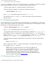
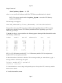
/sbin/vgdisplay -v
The display is shown in the following format.
Sample Screen (partial):
file:///H|/CSDoc/leotsg/section2.html (18 of 30) [01/12/2000 11:50:32 AM]
11.00.01 Operating and Maintenance Procedures
file:///H|/CSDoc/leotsg/section2.html (19 of 30) [01/12/2000 11:50:32 AM]
11.00.01 Operating and Maintenance Procedures
4. Obtain a value for volume_path from the vgdisplay -v command. A
volume_path in the above display is /dev/vg00/lvo11.
5. Enter the following command to determine if the disk being replaced is mirrored or
nonmirrored:
/sbin/lvdisplay lv_name
where lv_name is the path name obtained in Step 4. Repeat for each logical volume.
The display is shown in the following format.
Sample Screen (partial):
The Mirror copies field shows how many mirrors the disk has (0, 1, or 2).
6. If the disk being replaced is a mirrored LVM disk, remove mirroring for all logical
volumes by entering:
lvreduce -m 0 lv_path pv_path
lv_path is the block device path name of the logical volume and pv_path is the
pathname of the physical volume (the disk to be replaced). Repeat this command for each
logical volume.
7. Remove the disk from its volume group by entering the following command:
vgreduce vg_name pv_path
file:///H|/CSDoc/leotsg/section2.html (20 of 30) [01/12/2000 11:50:32 AM]
11.00.01 Operating and Maintenance Procedures
where vg_name is the path name of the volume group (/dev/vg00 in the sample
vgdisplay -v display shown above) and pv_path is the path name of the physical
volume to be replaced (/dev/dsk/c0t0d0 in the sample vgdisplay -v display
shown above).
If the disk being replaced is non-mirrored, move all the data contained on the disk to another
disk by entering the following command:
/sbin/pvmove source_pv_path
dest_pv_path
where the source_pv_path argument is the path name of the physical
volume to be removed (example: /dev/dsk/c1t0d0) and the
dest_pv_path argument is the path name of the destination physical
volume (example: /dev/dsk/c0t0d0).
NOTE: The destination physical volume must be in
the same volume group as the source physical
volume.
2.7.1.8 Verifying Disk Drive Replacement
After the replacement disk drive is installed, the system automatically tests it and brings it online.
1. Verify that the replacement disk is operational by entering the following command:
/sbin/ftsmaint ls hw_path
where where hw_path is the hardware path of the disk drive.
2. Check the State and Status fields. The State field should be listed as CLAIMED
and the Status field should be listed as Online.
3. If the disk that was replaced was an online, non-mirrored LVM disk, restore data to the
new disk by entering the following command:
/sbin/pvmove source_pv_path
dest_pv_path
where the source_pv_path argument is the path name of the physical
volume where the data resides (example: /dev/dsk/c1t0d0) and the
dest_pv_path argument is the path name of the new physical volume
(example: /dev/dsk/c0t0d0).
4. If the disk that was replaced was an online, mirrored LVM disk, perform the following
steps to ensure that the data on the replacement disk is both synchronized and valid.
a. Use the vgcfgrestore command to restore LVM configuration
information to the new disk.
file:///H|/CSDoc/leotsg/section2.html (21 of 30) [01/12/2000 11:50:32 AM]
11.00.01 Operating and Maintenance Procedures
b. Use the vgchange -a -y command to reactivate the volume group to
which the disk belongs.
c. Use the vgsync command to manually synchronize all the extents in the
volume group.
5. If a failed disk was replaced, restore any volumes that were disabled by the disk drive
failure.
For more information on commands pertaining to disk maintenance, refer to the manual HP-UX
Operating System: Fault Tolerant System Administration (R1004H-04-ST).
2.7.1.9 Preparing to Remove a Tape Drive
Tape drives are not hot pluggable devices. Perform the following steps to suspend operation on the SCSI
bus associated with the failed tape drive.
1. Enter the following command to determine the hardware path of the failed tape drive.
/sbin/ftsmaint ls
2. Determine the hardware path of the tape drive to be removed.
The information in the State and Status fields of the display will show information
on the failed tape drive.
2.7.1.10 Verifying Tape Drive Replacement
1. After the tape drive is configured into the system using the addhardware command,
verify that the tape drive is configured into the system. To do this, enter the following
commands:
ioscan -fn -C tape
ftsmaint ls hw_path
where hw_path is the hardware path to the tape drive.
2. Confirm that the tape drive is present, CLAIMED, and Online, and that device special
files have been created for it in the /dev/dsk and /dev/rdsk directories.
There is substantial overlap between the ftsmaint and ioscan commands, but the
ftsmaint command does not include the device file names and the ioscan command
does not include the Status information.
3. Verify that you can read and write to and from the device. One way to do this is through
the tar command. In the following example, the first tar command writes the
/etc/passwd file to tape using a device special file shown in the ioscan output from
file:///H|/CSDoc/leotsg/section2.html (22 of 30) [01/12/2000 11:50:32 AM]
11.00.01 Operating and Maintenance Procedures
step 1. The second tar command displays the contents of the tape.
tar cvf /dev/rmt/c0t3d0best /etc/passwd
tar tvf /dev/rmt/c0t3d0best
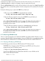
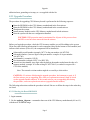
2.7.2 Maintaining Flash Cards
The Continuum 400 Series system contains two flash cards which are located on the PCIB card. The
flash cards are 20-MB PCMCIA cards used to perform the primary boot functions. The flash card
contains the primary bootloader, a configuration file, and the secondary bootloader. The HP-UX
operating system is stored on the root disk and booted from there.
A flash card contains three sections. The first is the label, the second is the primary bootloader, and the
third is the LIF.
Label Primary Bootloader Logical Interchange Format (LIF)
(lynx)
- CONF (configuration file)
- BOOT (secondary bootloader)
The following table describes the LIF files.
File Name
Description
CONF
The bootloader configuration file. This file is equivalent to the /stand/conf file
on the root disk.
BOOT
The secondary bootloader image, which is used to boot the kernel.
At system startup, the operating system boots from the flash card and assumes that it contains the correct
version of the bootloader configuration file in CONF. If there is no CONF file, the system cannot boot.
The operating system provides default values for key parameters in the bootloader configuration file. If it
is appropriate, permanent changes can be made to the system configuration by editing the
/stand/conf file on the root disk with a text editor and copying the file to the booting flash card.
Whenever you edit the /stand/conf file on the root disk you must remove the old copy of the CONF
file from the flash card (from which you booted) and replace it with the updated version of the
/stand/conf file before rebooting the system.
You can copy new configuration files and bootloaders to the LIF section using the flifcp and
flifrm commands. The size of the files varies depending on your configuration. You can view the size
and order of the files using the flifls command.
The LIF section on a flash card has a total space of 81188 blocks of 256K bytes, which is a little less than
20 MB. The following information is provided for each file:
● filename - The name of the file.
● type - The type of all these files is BIN, or binary.
● start - Indicates the block number at which the file starts.
file:///H|/CSDoc/leotsg/section2.html (23 of 30) [01/12/2000 11:50:32 AM]
11.00.01 Operating and Maintenance Procedures
●
●
●
size - The number of blocks used by the file.
implement - Not used and can be ignored.
created - Indicates the date and time the file was written to the flash card.
The flash cards can be read, and written to (as necessary) to update their files. The following utilities are
provided to help manage and maintain flash cards:
Utility
Use
flashboot
Copies data from a file on disk to
the bootloader area on the flash
card. Use this command to copy the
bootloader to the flash card. The
installation image is stored at
/stand/flash/lynx.obj.C
flashcp
Copies data from one flash card to
another.
flashdd
Copies data from flash images on
disk to a flash card. Use this
command to initialize a new flash
card with the installation flash
card image.
flifcmp
Compare a file on a flash card with
a file on the root disk.
flifcp
Copies a file from disk to the
flash card or from the flash card
to disk.
flifcompact
Eliminates fragmented storage space
on the flash card.
flirename
Rename a file on a flash card.
flifrm
Remove a LIF file from a flash
card.
flifls
Lists the files stored on a flash
card.
showboot
Display the device name of the
flash card from which the system
was booted.
2.7.2.1 Modifying Configuration Files
HP-UX assumes the flash card the system booted from contains the correct versions of the bootloader
file:///H|/CSDoc/leotsg/section2.html (24 of 30) [01/12/2000 11:50:32 AM]
11.00.01 Operating and Maintenance Procedures
configuration file CONF. This file must be kept up-to-date on the flash card. Also, whenever the
/stand/config file is edited for all changes, it must be copied to the flash card.
When the addhardware utility is used to add new hardware to the system, the /stand/ioconfig
file and flash card are automatically updated so that the configuration will be maintained for all system
reboots.
Perform the following steps to replace the CONF file on a flash card.
1. Make a copy of the old CONF file using the following command:
flifcp /dev/rflash/cxa0d0:CONF /tmp/cont.tmp
2. Enter the following command to remove the old CONF file from the flash card:
flifrm /dev/rflash/cxa0d0:CONF
where /dev/rflash/cxa0d0 is the device name of the flash card (x is the number of
the cardcage where the flash card resides), and CONF is the LIF file on the flash card
specified by the device name.
3. Enter the following command to copy the new /stand/conf to the flash card:
flifcp /stand/conf /dev/rflash/cxa0d0:CONF
where /dev/rflash/cxa0d0 is the device name of the flash card (x is the number of
the cardcage where the flash card resides), and CONF is the LIF file on the flash card
specified by the device name.
2.7.3 Burning PROM Code
All new or replacement boards come with the latest PROM code already installed. Therefore, it is not
necessary to burn the PROM of any new hardware. However, PROM code is occasionally released that
must be burned onto existing boards. The following sections describe how to update PROM code.
2.7.3.1 Burning CPU-Memory PROM Code
Use the following procedure to burn new PROM code into CPU-Memory boards.
CAUTION: Do not attempt to update CPU-Memory board PROM code if the system is
running with only one CPU-Memory boaerd.
1. Change to the /etc/stratus/prom_code directory.
Locate the new PROM code files and determine which file is correct. PROM code file
names use the following convention:
GNMMSccVV.Vxxx
file:///H|/CSDoc/leotsg/section2.html (25 of 30) [01/12/2000 11:50:32 AM]
11.00.01 Operating and Maintenance Procedures
where GNMM is the Modelx number, S is the submodel compatibility number (0-9), cc is
the source code identifier (fw is firmware), VV is the major revision number (0-99), V is
the minor revision number (0-9), and xxx is the file type (raw or bin). The following is
a sample CPU-Memory PROM code file for the online PROM:
G8xx0fw38.0.bin
2. Choose one of suitcases (0 or 1) and stop its CPU-Memory board from duplexing with its
partner by entering the following command:
ftsmaint nosync hw_path
where hw_path is the hardware path of the CPU-Memory board you want to stop
duplexing (either 0/0 or 0/1). The partner CPU-Memory board is now handling all system
processing.
3. Update the CPU-Memory board PROM by entering the following command:
ftsmaint burnprom -f prom_code hw_path
where prom_code is the full path name of the PROM code file to be downloaded
(/etc/stratus/prom_code/filename). hw_path is the hardware path of the
CPU-Memory board specified in Step 2 (either 0/0 or 0/1).
4. Switch processing to the newly updated CPU-Memory board by entering the following
command:
ftsmaint switch hw_path
where hw_path is the hardware path of the CPU-memory board specified in Step 2 (either
0/0 or 0/1). This step can take up to five minutes to complete; however, the prompt will
return immediately. The ftsmaint switch command copies the status of the running
CPU-Memory board to the newly updated CPU-Memory board, disables the running board,
and then enables the newly updated board.
5. Update the CPU-Memory PROM of the partner CPU-Memory board using the
ftsmaint burnprom command as described in Step 3.
6. Begin duplexing the boards by entering the following command:
ftsmaint sync hw_path
where hw_path is the hardware path of the CPU-memory board specified in Step 5 (either
0/0 or 0/1). The process is complete when both suitcases show a single green light.
7. Use the ftsmaint ls command to check that the boards have been returned to their
original status of Online Duplexed, and that the Board Rev field has the updated
with the new revision number.
file:///H|/CSDoc/leotsg/section2.html (26 of 30) [01/12/2000 11:50:32 AM]
11.00.01 Operating and Maintenance Procedures
2.7.3.2 Burning Console Controller PROM Code
The following procedure describes how to burn PROM code into a Console Controller.
1. Change to the /etc/stratus/prom_code directory.
Locate the new PROM code files and determine which files are correct. There are three files, one
for each PROM on the Console Controller. PROM code file names use the following convention:
MMMMSccVV.Vxxx
where MMMM is the Modelx number, S is the submodel compatibility number (0-9), cc is
the source code identifier (on for online, of for offline, and dg for diagnostic), VV is the
major revision number (0-99), V is the minor revision number (0-9), and xxx is the
file type (raw or bin). The following are sample Console Controller PROM code files for
the online PROM, offline PROM, and diagnostic PROM:
E5940on17.0bin
E5940of17.0bin
E5940dg17.0bin
2. Enter the following command to determine the location of the standby Console
Controller.
/sbin/ftsmaint ls
The Console Controller Status field will show Online Standby for the standby
board. The H/W Path field shows the hardware path of the Console Controller (either 1/0
or 1/1).
3. Update the PROM code on the standby Console Controller by entering the following
commands:
NOTE: The online PROM must be burned first.
/sbin/ftsmaint burnprom -F online -f prom_code
hw_path
/sbin/ftsmaint burnprom -F offline -f prom_code
hw_path
/sbin/ftsmaint burnprom -F diag-f prom_code hw_path
where prom_code is the full path name of the PROM code file to be downloaded
(/etc/stratus/prom_code/filename). hw_path is the hardware path of the
standby Console Controller (either 1/0 or 1/1).
NOTE: You must specify the standby Console Controller. An error message
will be displayed if you specify the online board.
file:///H|/CSDoc/leotsg/section2.html (27 of 30) [01/12/2000 11:50:32 AM]
11.00.01 Operating and Maintenance Procedures
4. When the prompt returns after burning the last partition, switch the status of the two
Console Controllers (the online board becomes the standby board and vice versa) by
entering the following command.
/sbin/ftsmaint switch hw_path
where hw_path is the hardware path of the Console Controller specified in Step 3 (either
1/0 or 1/1).
5. Check the status of the newly updated Console Controller using the following command:
/sbin/ftsmaint ls hw_path
where hw_path is the hardware path of the newly updated Console Controller (either 1/0
or 1/1). The
Status field should show Online.
6. Update the PROM code of the second Console Controller by using the ftsmaint
burnprom command as described in Step 3.
Once these commands are complete, both Console Controllers will be updated
with the same PROM code.
7. Return the Console Controllers to the state in which you found them by switching the
online/standby status of the two controllers as described in Step 4.
2.7.3.3 Burning U501 PCI Card PROM Code
Use the following procedure to burn new PROM code into U501 SCSI PCI cards.
1. Check the firmware revision of a U501 card by entering the following command:
/sbin/ftsmaint ls hw_path
where hw_path is the hardware path of the U501 card (U501s have hardware paths 0/2/7/0,
0/2/7/1, 0/2/7/2, 0/3/7/0, 0/3/7/1, and 0/3/7/2).
CAUTION: SCSI adapter cards can have a mix of external devices, or single- or
double-initiated buses attached to them. In this procedure, all devices except those
connected to the duplexed ports will be disrupted by the PROM update.
2. Notify users of any external devices or single-initiated logical SCSI buses attached to both SCSI
adapter cards that service will be disrupted. Disconnect the cables from both ports.
3. Determine which (if any) of the cards you plan to update contain resources (ports) on standby
duplexed status by entering the following command:
ftsmaint ls hw_path | grep -e Status -e Partner
where hw_path is the hardware path determined in step 1. For example, to identify the status for
the resources at 0/2/7/1, enter the command
file:///H|/CSDoc/leotsg/section2.html (28 of 30) [01/12/2000 11:50:32 AM]
11.00.01 Operating and Maintenance Procedures
ftsmaint ls 0/2/7/1 | grep -e Status -e Partner
4. Repeat step 3 for each resource in question.
5. Stop the standby resource from duplexing with its partner by entering the following command:
ftsmaint nosync hw_path
where hw_path is the hardware path of the standby resource. For example, to stop 0/3/7/1
from duplexing with 0/2/7/1, you would enter the command ftsmaint nosync
0/3/7/1.
Invoking ftsmaint nosync on a single resource also stops duplexing and (if necessary) puts
on standby status other resources (ports) on that card. Therefore, it is not necessary to repeat this
command for the other resources.
CAUTION: The next step stops all communication with devices connected
externally to the standby SCSI adapter card.
6. Update the PROM code on the standby card using the hardware address of one of the ports on
the card by entering the following:
ftsmaint burnprom -f prom_code hw_path
where prom_code i s the path name of the PROM code file, and hw_path is the path to the
standby card. For example, to update the PROM code in a U501 card in slot 7, card-cage 3, enter
the command ftsmaint burnprom -f u5010fw0st5raw 0/3/7/1.
7. Restart duplexing between the standby resource and its partner by entering
ftsmaint sync hw_path
where hw_path is the hardware path of the standby resource. For example, to restart duplexing
for 0/3/7/1, enter the command
ftsmaint sync 0/3/7/1.
NOTE: Invoking ftsmaint sync on a single resource also restarts (as
appropriate) duplexing for other resources (ports) on that card. Therefore, it is not
necessary to repeat this command for the other resources.
8. Reverse the standby status of the two cards and stop duplexing by entering the following:.
ftsmaint nosync hw_path
where hw_path is the hardware path of the duplexed port. For example, if 0/2/7/1 is one of the
duplexed ports of the active card, enter the command ftsmaint nosync 0/2/7/1.
CAUTION: The next step stops all communication with devices connected
externally to the standby SCSI adapter card.
9. Update the PROM code on the card that is now standby by entering
file:///H|/CSDoc/leotsg/section2.html (29 of 30) [01/12/2000 11:50:32 AM]
11.00.01 Operating and Maintenance Procedures
ftsmaint burnprom -f prom_code hw_path
where prom_code is the path name of the PROM code file, and hw_path is the path to the
standby card. For example, to update the PROM code in a U501 card in slot 7, card-cage 2, enter
the command ftsmaint burnprom -f u5010fw0st5raw 0/2/7/1.
10. When the prompt returns, enter the following command to restart duplexing between the
standby resource and its partner (and other resources on that card):
ftsmaint sync hw_path
where hw_path is the hardware path of the standby resource. For example, to restart duplexing for
0/2/7/1, enter the command
ftsmaint sync 0/2/7/1.
11. Check the status of the newly updated card and verify the current (updated) PROM code
version by entering the following command for both the resource and its partner:
ftsmaint ls hw_path
When the status becomes Online Standby Duplexed, the card has resumed duplex mode.
All Information © 1999 Stratus Computer, Inc.
file:///H|/CSDoc/leotsg/section2.html (30 of 30) [01/12/2000 11:50:32 AM]
Fault Isolation
3. Fault Isolation
This section contains information used to troubleshoot faults in the system. It contains the following subsections:
● Component Status LEDs
●
System component LEDs
●
System Log and Status Messages
●
Component Status
●
Fault Codes
●
Troubleshooting Procedures
3.1 Component Status LEDs
3.1.1 General LED information
LEDs can be in a three color arrangement, a two color arrangement or simply a green light. General explanations or
these categories follow.
3.1.1.1 Three color LED arrangements
Component status LEDs are either red, green, or yellow. (There is also an amber, system-wide status LED labeled
CABINET FAULT at the top of the cabinet in the front and rear.) When grouped in threes, they are arranged as
follows: red on top, yellow in the middle, green on the bottom.
They have the following general meanings:*
●
●
●
A red light indicates that the component is not functioning properly. In most cases, the component is broken and
needs to be replaced.
A yellow light indicates that the component is simplexed--that is, operating without a partner. Do not remove
this component. The yellow light is illuminated when the component is in the process of configuring itself with
its partner or when its partner has failed. Yellow LEDs can also indicate that a component is performing a
self-test.
In most cases, removing a yellow-lit part from the system causes its function to be suspended
(except in the PCI card cage on HP-UX systems).
A green light indicates that the component is operating properly
* The Tray 1 rectifier LED configuration is green/green/red, as explained in section 3.2.1.2.
A given status LED can also flash or remain steadily lit in combination with another status LED to indicate other
operating conditions, such as system power-up.
3.1.1.2 Two color LED arrangements
The disk drives and disk power supplies in the disk shelf (PSU0 and PSU1) have only two LEDS, red and green. When
a status light is illuminated, it indicates one of the following conditions:
● a red and green light indicates a fault with the disk power supply.
● a red light indicates a fault with the disk drive.
● a green indicates that the system is operating properly.
3.1.1.3 Single LEDs
file:///H|/CSDoc/leotsg/section3.html (1 of 12) [01/12/2000 11:50:41 AM]
Fault Isolation
●
●
●
If the amber cabinet fault LED (at the very top of the cabinet-- front and rear) is illuminated, a CRU within the
cabinet has produced an error condition. [Both cabinet fault lights (one front and one rear) are lit when one or
more components within the cabinet has failed. ]
If the amber PCI fault status LED is lit, there is an error within the PCI card cage. The PCI Fault status LED is
located on the front of the cabinet, at the bottom of the disk shelves.
There are a number of red or green disk shelf LEDs in the disk shelf (rear).
3.2. System Component LEDs
The following label, found on the cabinet, shows possible states for component LEDs and describes their meanings.
file:///H|/CSDoc/leotsg/section3.html (2 of 12) [01/12/2000 11:50:41 AM]
Fault Isolation
3.2.1 Power Supply LEDs
3.2.1.1 PCI Power Supply LEDs
LED State
Red
Meaning
On
Yellow Off
The power supply needs service.
Green Off
Red
Off
Yellow On
The power supply is simplexed (operating without a partner).
Green On
Red
Off
Yellow Off
The power supply and its partner are running duplexed.
Green On
Red
Off
Yellow Off
The system is not receiving power.
Green Off
Red
On
Yellow Off
Both of the ACUs are lit, one of the ACUs may need service.
Green On
3.2.1.2 Tray 1 Rectifier Status LEDs
LED State
Meaning
Green On
DC output power good.
Green On
AC input power good.
Red
Off
Green Off
Green On
AC input power good.
Red
On
Green Off
DC output power fault.
Green Off
Unit faulty and needs service.
Red
On
file:///H|/CSDoc/leotsg/section3.html (3 of 12) [01/12/2000 11:50:41 AM]
Fault Isolation
Green Off
Green Off
Red
Power is off.
Off
3.2.1.3 Disk Drive Power Supply Status LEDs
LED State
Red
Meaning
On
Yellow Off
The power supply needs service.
Green Off
Red
Off
Yellow On
The power supply is simplexed (operating without a
partner).
Green On
Red
Off
Yellow Off
The power supply and its partner are running duplexed.
Green On
Red
Off
Yellow Off
The system is not receiving power.
Green Off
Red
On
Yellow Off
Both of the ACUs are lit, one of the ACUs may need
service.
Green On
3.2.1.4 ACU Status LEDs
Color State
Red
Meaning
On
Yellow Off
One of the ACUs may need service. Both ACUs display this combination at the same time
to indicate that the status comparison has failed.
Green On
Red
On
Yellow Off
The ACU needs service.
Green Off
Red
Off
Yellow On
The ACU is simplexed, operating without a partner.
Green On
file:///H|/CSDoc/leotsg/section3.html (4 of 12) [01/12/2000 11:50:41 AM]
Fault Isolation
Red
Off
Yellow Off
The ACU and its partner are running duplexed.
Green On
Red
Off
Yellow Off
The system is not receiving power.
Green Off
3.2.2 Disk Drives
3.2.2.1 Disk Drive Status LED
Color State
Red
Meaning
Off
Disk is active.
Green On
Red
On
This is a faulty disk drive.
Green Off
Red
On
The disk drive is simplexed.
Green On
Red
Off
The disk drive is inactive.
Green Off
3.2.2.2 Terminator Module
This unit should be located above the three fan modules on the right of each of the two disk shelf backplanes. Since
the terminator should always be in S/E mode:
● The green LED over "S/E" on the right should be on
● The green LED over "LVD" (Low Voltage Differential) should not be on.
3.2.2.3 SES Unit Module
This unit is located above the three fan modules at the top middle of each of the two disk shelf backplanes. There is a
LED above the word "Temp", this LED is not used and should not be on. Next to "Temp" there is a "Mute" knob, this
also is not used and shouldn't be touched.
3.2.2.4 SE-SE I/O Repeater Module
This unit should be located above the three fan modules at the top left of each of the two disk shelf backplanes.
The SE-SE input unit insures that the terminator will be in SE mode. There are no LEDs to be concerned with in the
SE-SE I/O Repeater Module.
file:///H|/CSDoc/leotsg/section3.html (5 of 12) [01/12/2000 11:50:41 AM]
Fault Isolation
3.2.2.5 Fan Units (3)
Three fan units are located on the bottom part of each of the disk shelf backplanes.
The red LEDs in the Fan units should not be illuminated. If a red LED is on in one of the fan units, that unit should be
replaced fairly soon (the system is capable of running with only two fans but it is recommended that all three fans be
operational at all times).
3.2.3 Suitcase LEDs
3.2.3.1 Suitcase Power-On LED Sequence
Power-Up Stage Color State
Red
Meaning
Off
The suitcase is performing its self-test.
Yellow On
1
Green Off
Red
Off
The suitcase has passed its self-test and is being configured by the system.
Yellow Flashing
2
Green Off
Red
Off
The suitcase and its partner are online.
Yellow Off
3
Green On
Red
Off
Yellow On
4
The suitcase is online, but operating simplexed.
Green On
3.2.3.2 Suitcase Status LEDs
Color Suitcase 1 Suitcase 0
Red
Meaning
On
Off
Yellow Off
On
Suitcase 1 is broken, and suitcase 0 is simplexed (operating without its partner).
Green Off
Red
Flashing
On
Off
Suitcase 1 is partially broken; a component within the suitcase has failed.
Yellow Off
On
Green On
Red
Flashing
On
Flashing
Yellow On
On
Green On
On
Suitcase 0 is simplexed (operating without its partner).
A component within suitcase 1 has failed, and a different component within
suitcase 0 has failed. Both suitcases have simplexed components.
file:///H|/CSDoc/leotsg/section3.html (6 of 12) [01/12/2000 11:50:41 AM]
Fault Isolation
Red
Off
Off
Yellow Off
On
Green Off
Red
Off
On
Off
Yellow Off
Off
Green Off
Off
Suitcase 1 is not receiving power.
Both suitcases or the system is not receiving power.
3.2.4 PCI Cards
The PCI card cage label, shown below, is found on the PCI card cage (cabinet front). It shows possible states for PCI
LEDs and describes their meanings.
3.2.4.1 PCI Bridge Card Status LEDs
Color State
Red
Meaning
On
The PCI bridge card or flash card needs service.
Yellow Off
Green Off
Red
Off
Yellow Off
PCI bridge card and its card cage are fully operational. If both card cages show this state, the PCI
bridge cards are duplexed. NOTE: For HP-UX, the fully operational state is green and yellow LEDs
are on.
Green On
Red
Off
The PCI bridge card is simplexed, operating without a partner.
Yellow On
Green On
file:///H|/CSDoc/leotsg/section3.html (7 of 12) [01/12/2000 11:50:41 AM]
Fault Isolation
Red
Off
The PCI bridge card is performing a self-test.
Yellow On
Green Off
Red
Off
Yellow Flashing The PCI bridge card is not configured.
Green Off
Red
On
Yellow Off
The PCI bridge card is partially broken, it is OK to pull this card.
Green On
Red
On
Yellow On
The PCI bridge card is partially broken, do not pull this card.
Green On
3.3 System Log and Status Messages
System logs contain information concerning major system events and the time they occurred which can help detect and
evaluate system problems. Each time a significant event occurs, the syslog message logging facility enters an error
message into the systemlog at /var/adm/syslog/syslog.log.. Depending upon the severity of the error and
the phase of system operation, the same message might also be displayed on the console.
Several HP-UX commands provide status information about components or services. These commands are listed in the
following table.
Command
Type of Information
ftsmaint and ioscan
Hardware information
sar
System performance information
sysdef
Kernel parameter information
lp and lpstat
Print services information
ps
Process information
pwck and grpck
Password inconsistencies information
who and whodo
Current user information
ifconfig, netstat, ping, uustat, and
lanscan
Network services information
ypcat, ypmatch, yppoll, and ypwhich
Network Information Service (NIS) information
file:///H|/CSDoc/leotsg/section3.html (8 of 12) [01/12/2000 11:50:41 AM]
Fault Isolation
df and du
Disk and volume information
3.4 Component Status
The ftsmaint ls command lists the components in the system and identifies any components that have been
removed from service. The list serves as a simple troubleshooting tool to verify that all the components are present and
shows their status (in/out of service). Refer to Section 2.6.3 to view a sample ftsmaint ls output screen.
3.4.1 Software State Information
The system creates a node for each hardware device that is either installed or listed in the /stand/ioconfig file.
The State field in the ftsmaint ls display can show a hardware component to be in any one of the software
states shown in the following table.
State
Meaning
UNCLAIMED Initialization state, or hardware exists, and no software is associated with the node.
CLAIMED
The driver recognizes the device.
ERROR
The device is recognized, but it is in an error state.
NO_HW
The device at this hardware path is no longer responding.
SCAN
Transitional state that indicates the device is locked. A device is temporarily put in
the SCAN state when it is being scanned by the ioscan or ftsmaint utilities.
The software state of a hardware component can change. For example, a component is initially created in the
UNCLAIMED state when it is detected at boot time. The component moves to the CLAIMED state when it is recognized
and claimed by the appropriate driver. The transitions between the various software states are controlled by the
ioscan and ftsmaint utilities.
3.4.2 Hardware Status Information
In addition to a software state, each hardware component has a particular hardware status. The Status field in the
ftsmaint ls display can have any of the values shown in the following table.
Status
Online
Meaning
The device is actively working.
The device is not logically active, but it is operational. Using the ftsmaint
Online Standby switch or ftsmaint sync command can be used to change the device
status to Online.
Duplexed
The status is appended to the Online status to indicate that the device is
fully duplexed.
file:///H|/CSDoc/leotsg/section3.html (9 of 12) [01/12/2000 11:50:41 AM]
Fault Isolation
Duplexing
The status is appended to the Online or Online Standby status to
indicate that the device is in the process of duplexing. This transient status is
displayed after the ftsmaint sync or ftsmaint enable command has
been used on the CPU-Memory board.
Offline
The device is not functional or not being used.
Burning PROM
The ftsmaint burnprom command is in progress on the device.
The status of a hardware component can change. For example, a component could go from Online to Offline
because of a hardware or software error.
3.5 Fault Codes
The fault tolerant services return fault codes when certain events occur. Fault codes are displayed by the ftsmaint
ls command in the FCode field and by the ftsmaint ls -l command in the Fault Code field. The following
table lists and describes the fault codes.
Short Format
ls Format
2FLT
ADROK
BLINK
BPPS
BRKOK
CABACU
CABADR
CABBFU
CABBRK
CABCDC
CABCEC
CABCFG
CABDCD
CABFAN
CABFLT
CABFLT
CABLE
CABPCU
CABPSU
CABPWR
CABTMP
Long Format
ls -l Format
Both ACUs Faulted
Cabinet Address Frozen
Cabinet Fault Light Blinking
BP Power Supply
Faulted/Missing
Cabinet Circuit Breaker(s) OK
ACU Card Faulted
Cabinet Address Not Frozen
Cabinet Battery Fuse Unit Fault
Cabinet Circuit Breaker
Tripped
Cabinet Data Collector Fault
Central Equipment Cabinet
Fault
Cabinet Configuration
Incorrect
Cabinet DC Distribution Unit
Fault
Broken Cabinet Fan
Cabinet Fault Detected
Cabinet Fault Light On
PCI Power Cable Missing
Cabinet Power Control Unit
Fault
Cabinet Power Supply Unit
Fault
Broken Cabinet Power
Controller
Cabinet Battery Temperature
Fault
Explanation
Both ACUs are faulted.
The cabinet address is frozen.
The cabinet fault light is blinking.
The BP power supply is either faulted or missing.
The cabinet circuit breaker(s) are OK.
The ACU card is faulted.
The cabinet addresses are not frozen.
The cabinet battery fuse unit fault occurred.
A circuit breaker in the cabinet was tripped.
The cabinet data collector faulted.
A fault was recorded on the main cabinet bus.
The cabinet contains an illegal configuration.
A DC distribution unit faulted.
A cabinet fan failed.
A component in the cabinet faulted.
The cabinet fault light is on.
This PCI backpanel cable is not attached.
A power control unit faulted.
A power supply unit faulted.
A cabinet power controller failed.
A cabinet battery temperature above the safety
threshold was detected.
file:///H|/CSDoc/leotsg/section3.html (10 of 12) [01/12/2000 11:50:41 AM]
Fault Isolation
CABTMP
Cabinet Temperature Fault
CDCREG
Cabinet Data Registers Invalid
CHARGE
Charging Battery
DSKFAN
ENC OK
FIBER
FIBER
Disk Fan Faulted/Missing
SCSI Peripheral Enclosure OK
SCSI Peripheral Enclosure
Fault
Cabinet Fiber-Optic Bus Fault
Cabinet Fiber-Optic Bus OK
HARD
Hard Error
HWFLT
Hardware Fault
ILLBRK
Cabinet Illegal Breaker Status
ENCFLT
IS
LITEOK
Invalid ACU Register
Information
IOA Chassis Power Supply OK
IOA Chassis Power Supply
Fault
In Service
Cabinet Fault Light OK
MISSNG
Missing replaceable unit
MTBF
Below MTBF Threshold
NOPWR
No Power
Cabinet Fan Speed Override
Active
INVREG
IPS OK
IPSFlt
OVERRD
PC Hi
Power Controller Over Voltage
PCIOPN
PCVOTE
PCI Card Bay Door Open
Power Controller Under
Voltage
Power Controller Voter Fault
PSBAD
Invalid Power Supply Type
PCLOW
PSU OK
PSUs
Cabinet Power Supply Unit(s)
OK
Multiple Power Supply Unit
Faults
PWR
Breaker Tripped
REGDIF
ACU Registers Differ
A cabinet temperature above the safety threshold
was detected.
The cabinet data collector is returning incorrect
register information. Upgrade the unit.
A battery CRU/FRU is charging. To leave this
state, the battery needs to be permanently bad or
fully charged.
The disk fan either faulted or is missing.
The SCSI peripheral enclosure is OK.
A device in the tape/disk enclosure faulted.
The cabinet fiber-optic bus faulted.
The cabinet fiber-optic bus is OK.
The driver reported a hard error. A hard error
occurs when a hardware fault occurs that the
system is unable to correct. Look at the syslog
for related error messages.
The hardware device reported a fault. Look at the
syslog for related error messages.
The cabinet data collector reported an invalid
breaker status.
A read of the ACU registers resulted in invalid
data.
The IOA chassis power supply is OK.
An I/O Adapter power supply fault was detected.
The CRU/FRU is in service.
The cabinet fault light is OK.
The ACU on the DNCP Series 400-CO (PA-8500) is
missing, electrically undetectable, removed, or
deleted.
The CRU/FRU’s rate of transient and hard failures
became too great.
The CRU/FRU lost power.
The fan override (setting fans to full power from
the normal 70%) was activated.
An over-voltage condition was detected by the
power controller.
The PCI card-bay door is open.
An under-voltage condition was detected by the
power controller.
A voter fault was detected by the power controller.
The power supply ID bits do not match that of any
supported unit.
The cabinet power supply unit(s) are OK.
Multiple power supply units faulted in a cabinet.
The circuit breaker for the PCIB power supply
tripped.
A comparison of the registers on both ACUs
showed a difference.
file:///H|/CSDoc/leotsg/section3.html (11 of 12) [01/12/2000 11:50:41 AM]
Fault Isolation
SOFT
Soft Error
SPR OK
SPRPCU
TEMPOK
Cabinet Fan Speed Override
Completed
Cabinet Spare (PCU) OK
Cabinet Spare (PCU) Fault
Cabinet Temperature OK
USER
User Reported Error
SPD OK
The driver reported a transient error. A transient
error occurs when a hardware fault is detected, but
the problem is corrected by the system. Look at the
syslog for related error messages.
The cabinet-fan speed override completed.
The cabinet spare (PCU) is OK.
The power control unit spare line faulted.
The cabinet temperature is OK.
A user issued ftsmaint disable to disable the
hardware device.
3.6 Troubleshooting Procedures
When a fault occurs, several things can happen. If it is a non-critical fault, the system will continue to process data. If it
is a critical fault, the system (or a subsystem) may be inoperative. When troubleshooting the system, determine the
fault first by using the LEDs and screen messages. Then, verify that the component(s) is out of service using the
ftsmaint ls command (Section 2.6.3), error logs, and diagnostic tests. This flow is shown in the Troubleshooting
Flow below.
Troubleshooting Flow
When troubleshooting system faults, use the following process:
● Check the console terminal for fault information.
● Locate the failed component(s) using the LEDs.
● Verify the component is bad by using software commands/error logs.
● Remove and replace the failed component.
● Check to make sure the problem is resolved.
file:///H|/CSDoc/leotsg/section3.html (12 of 12) [01/12/2000 11:50:41 AM]
Hardware Removal Procedures
4a. Hardware Removal and Replacement Procedures
This section lists the Field Replaceable Units (FRUs) and Distributor Replaceable Units (DRUs) in the PA-8500
Continuum Series 400 system and describes the removal and replacement procedures for each one. In some
instances, FRUs/DRUs are duplexed and may be removed and replaced without total removal of power, and thus,
without loss of continuous processing. However, in most instances, the system must be shut down and both main
power switches turned off prior to removal and replacement of the FRU/DRU. The list of FRUs/DRUs in the
following table notes which FRUs/DRUs require which degree of power removal before removal and replacement
procedures can be performed.
4.1 List of FRUs/DRUs
The following table lists the FRUs/DRUs in the PA-8500 Continuum Series 400 system and shows the location of
each FRU/DRU. It also indicates whether or not the FRU/DRU requires any degree of power removal.
FRU/DRU
Location
Power Removal Required
AC Power Chassis/Suitcase Cable
Assembly (AW-001038)
Mounted on Tray 1 rear and connects
suitcase power supply to AC power
chassis.
System must be shutdown and both
main power switches turned off.
Tray 1 (Power Front End Tray)
(AA-P28200)
Above the disk shelves and below
Tray 2.
System must be shutdown and both
main power switches turned off.
Tray 2 (PCI/ACU Power Tray)
(AA-P28300)
Above the disk shelves and Tray 1.
System must be shutdown and both
main power switches turned off.
CPU Backplane (AA-E25800)
Below PCI card cages.
System must be shutdown and both
main power switches turned off.
PCI Backplane (AA-E26100)
Below disk shelves.
System must be shutdown and both
main power switches turned off.
Backplane Interconnect PCB
(AA-E26200)
Connects PCI backplane to CPU
backplane.
System must be shutdown and both
main power switches turned off.
PCI Fault Display PCB
(AA-E26600)
On top of PCI card cage.
PCI power supply on the affected
side of cabinet must be turned off.
Cabinet Fault Display PCB
(AA-E26500)
On top of cabinet.
System must be shutdown and both
main power switches turned off.
Disk Shelf (AA-D84000,
AA-D84001) (84000 is the disk
shelf with fans, SES and 48v DC
Power Supplies; AA-D84001 is
the empty disk shelf-used for
replacements)
Below power chassis.
Cabinet must be shutdown and
both main power switches turned
off.
file:///H|/CSDoc/leotsg/section4a.html (1 of 23) [01/12/2000 11:50:51 AM]
Hardware Removal Procedures
Disk Shelf Power Cable
(AW-001036)
Connects disk shelf to power
chassis.
Cabinet must be shutdown and
both main power switches turned
off.
For the hot pluggable procedure
(also listed) system shutdown is
not necessary.
Disk Shelf SCSI Data Cable
(AW-001034)
Connects lower/upper disk shelf
(via SCSI signal repeater) to PCI
backplane.
Cabinet must be shutdown and
both main power switches turned
off.
CPU Backplane Power Cable
(AW-001048)
Connects CPU backplane to DC
power chassis.
Cabinet must be shutdown and
both main power switches turned
off.
PCI Backplane Power Cable
(AW-001047)
Connects PCI backplane to DC
power chassis.
Cabinet must be shutdown and
both main power switches turned
off.
SCSI Data Cable - PCI Bridge
Card/PCI Backplane
(AW-000954)
Connects PCI bridge card to PCI
backplane.
Both PCI power supplies must be
turned off.
Cable - PCI Backplane/PCI Fault
Display PCB (AW-001113)
Connects PCI backplane to PCI
fault display PCB.
PCI power supply on the affected
side of cabinet must be turned off.
U450 16-port Support Bracket
(AK-000331)
Mounted on rear cabinet PCI card
cage.
No power removal necessary.
PCI Fault Display Cable
(AW-000982)
Connects cabinet fault display PCB
to PCI fault LED.
No power removal necessary.
Cabinet Fault Display PCB Cable
(AW-000959)
Connects PCI backplane to cabinet
fault display PCB.
No power removal necessary.
Cable - Cabinet Fault Display
PCB/Cabinet Fault LEDs
(AW-000985)
Connects cabinet fault display PCB
to cabinet fault LEDs.
No power removal necessary.
The following are optional FRUs whose installation is documented in the PA-8500 Continuum Series 400
Unpacking Instructions:
● Seismic 4 mounting kit (AX-000063)
● Seismic 1 mounting kit (AX-000064)
4.2 System Shutdown/Startup
If total power removal is required, the system must be shut down prior to removing power and rebooted after the
replacement unit is installed. Refer to Section 2 for the system shutdown procedure.
file:///H|/CSDoc/leotsg/section4a.html (2 of 23) [01/12/2000 11:50:51 AM]
Hardware Removal Procedures
4.3 Power Removal
Power is removed from one side of the system by lifting the appropriate AC circuit breaker, then unscrewing the
thumbscrew and pulling out the latch, which turns off the power to that side. This will simplex the system. If the
system must be powered down completely, do the above procedure on both sides.
(See Figure 4-1)
CAUTION: If the system needs to be simplexed (power removed from one side of the cabinet), verify that
there are no red LEDs or system console messages indicating a failed duplexed component on the side of the
system that will remain powered on. If both components in a duplexed pair are removed, a system crash will
occur.
Figure 4-1. Main Power Switch/AC Input Breaker
4.4 Access Doors
The access doors that often need to be opened in order to access FRUs are the PCI card cage access doors and the
access door behind the PCI backplane. These are shown in Figure 4-2 and Figure 4-3. Refer to them as necessary
during the FRU removal procedures.
Figure 4-2. PCI card Cage Access Doors (Rear of system)
file:///H|/CSDoc/leotsg/section4a.html (3 of 23) [01/12/2000 11:50:51 AM]
Hardware Removal Procedures
NOTE: Open one PCI card cage door at a time
Figure 4-3. PCI Backplane Access Door (Front of system)
NOTE: To open the locking knobs on the PCI backplane access door, you may need a torx head
wrench tool.
4.5 Hardware Removal Procedures
This section contains the removal procedures for the FRUs listed in the preceding table. Each of these procedures
indicates any power removal requirements for the FRU. If a customer replaceable unit (CRU) needs to be removed
during the procedure, it is designated as a CRU. If necessary, refer to Chapter 3 in the HP-UX Operating System:
Continuum Series 400 Operation and Maintenance Guide Release 1.0 (R025H-01-ST) for its removable procedure.
To perform the replacement procedure for each FRU, reverse the removable procedure. If any special replacement
considerations are necessary, a replacement note is included.
file:///H|/CSDoc/leotsg/section4a.html (4 of 23) [01/12/2000 11:50:51 AM]
Hardware Removal Procedures
4.5.1 AC Power Chassis/Suitcase Cable Assembly (AW-001038)
1. Shut down the system from the system console.
2. Open the cabinet front door and turn off the main power switch/AC circuit breaker (located in Tray 1) that
provides power to the side of the cabinet containing the failed suitcase power cable.
(See Figure 4-1.)
3. Open the cabinet rear door and disconnect the Molex connector (P3 or P4) of the AW-001036 cable on the faulty
side (See Figure 4-4)
Figure 4-4. Disconnecting the Molex Connector on the AW-001036 Cable
4. Disconnect the red and black power cable from the very top left or right of Tray 2 (depending on which side is
faulty). The other end of this is permanently attached to the AW-001038 assembly. (See Figure 4-5)
Figure 4-5. Disconnecting the Red and Black Cables from the AC Power Chassis
Refer to Figure 4-6 when performing the following step.
5. Disconnect the cables connected to the faulty AW-001038 assembly at the AC power tray 1 (rear). Some of the
cables do not detach from the AW-001038 assembly and therefore do not have separate part numbers.
file:///H|/CSDoc/leotsg/section4a.html (5 of 23) [01/12/2000 11:50:51 AM]
Hardware Removal Procedures
●
●
One AW-001042 cable from AW-001038 assembly ( P2 or P3)
One AW-B1901X AC power cord from the top left of the left or right AW-001038 assembly (depending on
which side is faulty).
Figure 4-6. Disconnecting the Cables from the AC Power Chassis
6. At the bottom rear of the cabinet, remove the nut securing the two ground wires to the cabinet frame. (See Figure
4-7.)
Figure 4-7. Removing the Ground Wires from the Cabinet Frame
7. Loosen the two captive screws and remove the metal plate of the AW-001038 cable assembly, at J310 or J311
(depending on which side is faulty). This is located below the suitcase chassis in the cabinet rear . (See Figure
4-8.)
file:///H|/CSDoc/leotsg/section4a.html (6 of 23) [01/12/2000 11:50:51 AM]
Hardware Removal Procedures
Figure 4-8. Removing the Metal Plate from the Suitcase Power Cable
To disengage the (six-wire) multicolored cable (of the AW-001038 assembly) complete the following steps:
8. Remove the 12 screws securing the PCI/suitcase chassis. (See Figure 4-9.)
Figure 4-9. Removing the Screws from PCI/Suitcase Chassis
9. Disconnect the two AW-001034 cables from the rear of the disk shelf. This step is necessary so that the
AW-001034 cables are not strained while moving the PCI/suitcase chassis.
(See Figure 4-10.)
file:///H|/CSDoc/leotsg/section4a.html (7 of 23) [01/12/2000 11:50:51 AM]
Hardware Removal Procedures
Figure 4-10. Disconnecting the AW-001034 Cables from the Disk Shelf
10. Remove the major four thumbscrews at the perimeter of the faulty AW-001038 assembly
(located at the rear of AC power tray 1). (See Figure 4-11.)
Figure 4-11. Unscrewing the AW-001038 Assembly from the AC Power Backplane
11. Carefully push the PCI/suitcase chassis a few inches forward until there is enough space to access and remove
the 6-wire multicolored suitcase power cable from the left or right side of the cabinet (depending on which side is
faulty). (See Figure 4-12.) The entire AW-001038 assembly is now detached.
file:///H|/CSDoc/leotsg/section4a.html (8 of 23) [01/12/2000 11:50:51 AM]
Hardware Removal Procedures
Figure 4-12. Accessing the Suitcase Power Cable
Replacement Note: When installing the replacement suitcase power cable, carefully route the cable along the
cabinet frame so that when the PCI/suitcase chassis is pushed back into place, it will not pinch the cable.
4.5.2 Tray 1 (Power Front End) AA-P28200
1. Shut down the system from the system console.
2. Open the cabinet front door and turn off both main power switches. (See Figure 4-1.)
3. Standing at the front of the cabinet, remove both the rectifiers (CRUs) from Tray 1. (See Figure 4-13.)
Figure 4-13. Removing Rectifiers from Tray 1
4. Unplug both the AC power cables (AW-B190XX) from their external plugs.
5. Open the cabinet rear door.
6. (See Figure 4-14.) From both the suitcase power cable assemblies (AW-001038) unplug:
● The AC power cables (AW-B190XX) (one on each of the two suitcase power cable assembly boxes)
● The AW-001042 cables (one on each of the two suitcase power cable assembly boxes)
file:///H|/CSDoc/leotsg/section4a.html (9 of 23) [01/12/2000 11:50:51 AM]
Hardware Removal Procedures
Figure 4-14. Removing Cables from the AW-001038 Assembly
7. Remove the major four thumbscrews at the perimeter of the both the AW-001038 suitcase power cable
assemblies (located at the rear of AC Power Tray 1). (See Figure 4-15.)
Figure 4-15. Unscrewing the AW-001038 Assembly from the AC Power Backplane
Note: you will need to support the suitcase power cable assembly (AW-001038) at this point to make
sure that its attached cables are not strained.
8. At the cabinet front, unscrew the four screws (two on either side) securing Tray 1. Carefully pull Tray 1 forward
to remove it. (See Figure 4-16.)
file:///H|/CSDoc/leotsg/section4a.html (10 of 23) [01/12/2000 11:50:51 AM]
Hardware Removal Procedures
Figure 4-16. Removing Tray 1 from the Cabinet
4.5.3 Tray 2 (PCI/ACU Power Tray) AA-P28300
1. Shut down the system from the system console.
2. Open the cabinet front door and turn off both main power switches. (See Figure 4-1.)
3. Standing at the front of the cabinet, unscrew and remove both the PCI power supplies and ACU's (CRUs) from
Tray 2. (See Figure 4-17)
Figure 4-17. Removing PCI Power Supplies and ACU's from Tray 2
4. Open the cabinet rear door.
5. (See Figure 4-18 ) From the Tray 2 backplane, unscrew the following connectors using a small standard
screwdriver:
● Two AW-001047 cables from J008 and J009
● One AW-001042 cable from J010
● Two red/black cables, part of the CPU/Suitcase Power Assembly (AW-001038) from the top left and right of
file:///H|/CSDoc/leotsg/section4a.html (11 of 23) [01/12/2000 11:50:51 AM]
Hardware Removal Procedures
●
the Power Tray 2 backplane
One ACU/CPU to fault display cable (AW-001048) from J007
Figure 4-18. Tray 2 Backplane
6. At the cabinet front, unscrew the four screws (two on either side) securing Tray 2 and carefully pull Tray 2
forward to remove it. (See Figure 4-19.)
Figure 4-19. Removing the Screws from Tray 2 Front
4.5.4 CPU Backplane (AA-E25800)
1. Shut down the system from the system console.
2. Open the cabinet front door and turn off both main power switches. (See Figure 4-1.)
file:///H|/CSDoc/leotsg/section4a.html (12 of 23) [01/12/2000 11:50:51 AM]
Hardware Removal Procedures
3. Remove the two suitcases (CRUs) from the cabinet.
4. Open the cabinet rear door.
Refer to Figure 4-20 when performing the following steps.
5. Remove the cables from the serial ports on the CPU backplane cover.
6. Using a 3/16" nut driver, remove the standoffs on the four serial ports.
Figure 4-20. Removing the Cables and Standoffs from the CPU Backplane
7. Remove the four screws securing the cover to the CPU backplane. (See Figure 4-21.)
Figure 4-21. Removing the Screws from the CPU Backplane Cover
Refer to Figure 4-22 when performing the following steps.
8. Remove the 10 screws (four each in the upper and lower brackets, two in the center bracket) securing the CPU
backplane.
NOTE: The upper and lower brackets are removable. The center bracket is fixed.
9. Pull the CPU backplane straight out from its connector (located at the top center).
file:///H|/CSDoc/leotsg/section4a.html (13 of 23) [01/12/2000 11:50:51 AM]
Hardware Removal Procedures
Figure 4-22. Removing the CPU Backplane
4.5.5 PCI Backplane (AA-E26100)
1. Shut down the system from the system console.
2. Open the cabinet front door and turn off both main power switches. (See Figure 4-1.)
3. Open the cabinet rear door and open the left PCI card cage door. Remove all the PCI cards (CRUs) from the
left side of the PCI card cage. Label all the cables as you remove them from the cards. Close the left PCI card cage
door.
4. Open the right PCI card cage door. Remove all the PCI cards (CRUs) from the right side
of the PCI card cage. You may need to use a torx head wrench tool set (star hex tool) to open the PCI card
cage. Label all the cables as you remove them from the cards. Close the right PCI card cage door.
5. At the front of the cabinet, open the access door to the PCI backplane. (See Figure 4-2.)
6. Disconnect the following cables from the PCI backplane: (See Figure 4-23.)
● AW-001047
● AW-000959
● AW-001034 (2)
Figure 4-23. Disconnecting the Cables from the PCI Backplane
file:///H|/CSDoc/leotsg/section4a.html (14 of 23) [01/12/2000 11:50:51 AM]
Hardware Removal Procedures
NOTE: Place a drop cloth or sheets of paper over the top of the suitcases to prevent hardware from falling
into them during the next steps.
Refer to Figure 4-24 when performing the following steps.
7. Using a 3/16" nut driver, remove the standoffs from the three connectors on the PCI backplane EMI shield.
8. Remove the 12 screws securing the EMI shield to the PCI backplane.
Figure 4-24. Removing the Standoffs and Screws from the PCI Backplane EMI Shield
Refer to Figure 4-25 when performing the following steps.
9. Remove the two screws securing the PCI backplane to the divider panel.
10. Carefully pull the PCI backplane straight out from its connector (located at the bottom center) and remove it
from the cabinet.
file:///H|/CSDoc/leotsg/section4a.html (15 of 23) [01/12/2000 11:50:51 AM]
Hardware Removal Procedures
Figure 4-25. Removing the PCI Backplane
4.5.6 Backplane Interconnect PCB (AA-E26200)
1. Shut down the system from the system console.
2. Open the cabinet front door and turn off both main power switches. (See Figure 4-1.)
3. Remove the CPU backplane. (Refer to the CPU Backplane (AA-E25800) removal procedure.)
4. Open the two ejector levers on the sides of the backplane interconnect PCB and slide it out of the cabinet. (See
Figure 4-26.)
Figure 4-26. Removing the Backplane Interconnect PCB
4.5.7 PCI Fault Display PCB (AA-E26600)
1. Open the cabinet front door.
2. Turn off the switch on the PCI power supply that provides power to the side of the cabinet where the failed PCI
fault display is located (the switch is located on the sides of Tray 2). (See Figure 4-27)
file:///H|/CSDoc/leotsg/section4a.html (16 of 23) [01/12/2000 11:50:51 AM]
Hardware Removal Procedures
Figure 4-27. PCI Power Switch
3. Open the cabinet rear door.
NOTE: There are two PCI fault display PCBs. Each one is secured to the panel at the top of the card cage
(containing card cage slot numbers and LEDs) with three screws, two of which are secured at the top of the
panel, and the other at the bottom.
4. Open the card cage door on the side where the failed PCI fault display PCB is located.
(See Figure 4-2.)
5. Remove the two top screws securing the failed PCI fault display PCB to the panel.
(See Figure 4-28.)
Figure 4-28. Removing the Top Screws from the PCI Fault Display PCB
6. Remove the bottom screw securing the failed PCI fault display PCB to the panel. (See Figure 4-29.)
file:///H|/CSDoc/leotsg/section4a.html (17 of 23) [01/12/2000 11:50:51 AM]
Hardware Removal Procedures
Figure 4-29. Removing the Bottom Screws from the PCI Fault Display PCB
7. Disconnect the PCI fault display PCB from the ribbon cable. (See Figure 4-30.)
Figure 4-30. Disconnecting the PCI Fault Display PCB from the Ribbon Cable
4.5.8 Cabinet Fault Display PCB (AA-E26500)
NOTE: There are two cabinet fault display PCBs. One is located behind the PCI card cage and the other is in
the cabinet top cover.
Cabinet Fault Display PCB (behind PCI card cage)
1. Shut down the system from the system console.
2. Open the cabinet front door and turn off both main power switches. (See Figure 4-1.)
3. Open the cabinet front door.
4. Open the access door to the PCI backplane. (See Figure 4-3.)
Refer to Figure 4-31 when performing the following steps.
file:///H|/CSDoc/leotsg/section4a.html (18 of 23) [01/12/2000 11:50:52 AM]
Hardware Removal Procedures
NOTE: Before performing the next step, place a sheet of paper over the left suitcase to prevent any screws
from falling into the suitcase.
5. Disconnect the AW-000959 and AW-000982 cables from the cabinet fault display PCB.
6. Remove the four screws securing the cabinet fault display PCB to the chassis.
Figure 4-31. Disconnecting Cables and Removing Screws from the Cabinet Fault Display
PCB
Cabinet Fault Display PCB (inside cabinet top cover)
1. Shut down the system from the system console.
2. Open the cabinet front door and turn off both main power switches. (See Figure 4-1.)
3. Open the cabinet rear door.
4. At the top of the cabinet, remove the AW-001048 cable from the cabinet fault display PCB. (See Figure 4-32.)
Figure 4-32. Disconnecting the Cable from Cabinet Fault Display PCB
5. Using pliers or a 15/16" open end wrench, remove the four bolts securing the cabinet top cover and then remove
the cover from the cabinet. (See Figure 4-33.)
file:///H|/CSDoc/leotsg/section4a.html (19 of 23) [01/12/2000 11:50:52 AM]
Hardware Removal Procedures
Figure 4-33. Removing the Bolts from Cabinet Top Cover
Refer to Figure 4-34 when performing the following steps.
6. Using an 11/32" nut driver, remove the four nuts securing the cabinet fault display PCB to the top cover.
7. Disconnect the AW-000985 cable from the cabinet fault display PCB (at the top of the cabinet).
Figure 4-34. Removing the Nuts and Disconnecting the Cable from the Cabinet Fault Display PCB
4.5.9 Disk Shelf, SCSI (AA-D84000, AA-D84001)
AA-D84000 is the disk shelf with fans, SES and 48v DC Power Supplies;
AA-D84001 is the empty disk shelf-used for replacements
1. Shut down the system from the system console.
2. Open the cabinet front door and turn off both main power switches. (See Figure 4-1.)
3. Open the cabinet rear door.
4. Disconnect the AW-001036 connectors from the appropriate disk shelf (at the rear of the disk shelf on the
right ).(See Figure 4-35)
file:///H|/CSDoc/leotsg/section4a.html (20 of 23) [01/12/2000 11:50:52 AM]
Hardware Removal Procedures
Figure 4-35. Removing the AW-001036 Cable from the Disk Shelf Backplane
5. Disconnect the AW-001034 cable from the appropriate disk shelf (at the rear of the disk shelf on the left in the
SE-SE I/O repeater module). (See Figure 4-36)
Figure 4-36. Removing the AW-001034 Cable from the Disk Shelf Backplane
6. Open the cabinet front door.
7. Standing at the front of the cabinet, remove all the disk power supplies and disk drives (CRUs) from the disk
shelf. (See Figure 4-37.)
file:///H|/CSDoc/leotsg/section4a.html (21 of 23) [01/12/2000 11:50:52 AM]
Hardware Removal Procedures
Figure 4-37. Disk Shelf with Partially Removed Disk Power Supplies and Disk Drives
8. Remove the two screws in each of the four trim plates on both sides of the disk shelf. (See Figure 4-38.)
Figure 4-38. Removing the Trim Plates on the Left and Right Sides of the Disk Shelf
9. Standing at the rear of the cabinet, gently push the disk shelf forward to enable you get a good grasp of it from
the front of the cabinet.
10. Standing at the front of the cabinet, carefully slide the disk shelf out of the cabinet. (See Figure 4-39.)
file:///H|/CSDoc/leotsg/section4a.html (22 of 23) [01/12/2000 11:50:52 AM]
Hardware Removal Procedures
Figure 4-39. Removing the Disk Shelf
file:///H|/CSDoc/leotsg/section4a.html (23 of 23) [01/12/2000 11:50:52 AM]
4.5.10. Disk Shelf Power Cable (AW-001036)
1. Shut down the system from the system console.
2. Open the cabinet front door and turn off both main power switches. (See Figure 4-1)
3. Open the cabinet rear door.
4. Disconnect the faulty AW-001036 disk shelf power cable from both the Molex connectors (P2 and P3)
connecting to AW-001038 which attaches to the AC power chassis). (See Figure 4-40.)
Figure 4-40. Disconnecting the Disk Shelf Power Cable from the Molex Connectors
5. Disconnect the faulty AW-001036 disk shelf power cable connector from the plug at the far right of the
disk shelf rear. (See Figure 4-41.)
Figure 4-41. Disconnecting the Disk Shelf Power Cable from the Disk Shelf
4.5.10HS Hot Swap Replacement of Disk Shelf Power Cable (AW-001036)
1. At the cabinet front, pull PSU0 and PSU1 disk power supplies from the top disk shelf. (See Figure 4-42.)
Figure 4-42. Pulling the Disk Power Supplies from the Disk Shelf
2. At the cabinet rear, unscrew the AW-001036 connector ("P2") from the top disk shelf (See Figure 4-43)
Figure 4-43. Unscrewing the AW-001036 Connector
3. Unplug the AW-001036 from one Molex connector (See Figure 4-44)
Figure 4-44. Unplugging the AW-001036 from the Molex Connector
Refer to the appropriate figures above for the following steps:
4. Plug the new AW-001036 replacement into the emptied Molex connector.
5. Screw the AW-001036 connector into the empty plug on the top disk shelf.
6. At the cabinet front, insert PSU0 and PSU1 disk power supplies back into the top disk shelf.
7. WAIT for the disk drives to mirror up (This may take several hours).
8. Pull PSU0 and PSU1 disk power supplies from the bottom disk shelf.
9. At the cabinet rear, unscrew the AW-001036 connector ("P1") from the bottom disk shelf and screw in
the new AW-001036 connector.
10. Unplug the AW-001036 from the other end of the Molex connector and reconnect the new AW-001036
cable.
11. At the cabinet front, insert PSU0 and PSU1 disk power supplies back into the bottom disk shelf.
4.5.11. Disk Shelf SCSI Data Cable (AW-001034)
1. Shut down the system from the system console.
2. Open the cabinet front door and turn off both main power switches. (See Figure 4-1)
3. Open the cabinet rear door.
4. Disconnect the failed disk shelf SCSI data cable (AW-001034) from the disk shelf (rear). (See Figure 445.)
Figure 4-45. Disconnecting the SCSI Data Cable from the Disk Shelf (rear)
5. Open the cabinet front door.
6. Open the access door to the PCI backplane. (See Figure 4-3.)
7. Disconnect the other end of the disk shelf SCSI data cable (AW-001034) from the appropriate plug on
the PCI backplane. (See Figure 4-46.)
Figure 4-46. Disconnecting the SCSI Data Cable from the PCI Backplane
4.5.12 CPU Backplane Power Cable (AW-001048)
1. Shut down the system from the system console.
2. Open the cabinet front door and turn off both main power switches. (See Figure 4-1.)
3. Remove the 12 screws securing the PCI/suitcase chassis. (See Figure 4-47.)
Figure 4-47. Removing the Screws from the PCI/Suitcase Chassis
4. Open the cabinet rear door.
5. Disconnect the AW-001034 cables from the disk shelf (rear). (See Figure 4-48.) [This step is necessary
so that the AW-001034 cables are not strained while moving the PCI/suitcase chassis.]
Figure 4-48. Disconnecting the Disk Shelf SCSI Data Cable Connectors from the Disk Shelf (rear)
6. At the very top of the cabinet, disconnect the CPU backplane power cable (AW-001048) from the cabinet
fault display PCB. (See Figure 4-49.)
Figure 4-49. Disconnecting The CPU Backplane Power Cable from the Cabinet Fault Display PCB
7. (See Figure 4-50.) On the AC power chassis, disconnect:
●
●
The AW-001048 CPU backplane power cable from J007
Two AW-001047 PCI backplane power cables from J008 and J009 (This will kept avoid strain on
this cable when moving the PCI/suitcase chassis)
Figure 4-50. Disconnecting the CPU and PCI Backplane Power Cables from the AC Power Chassis
8. At the bottom of the cabinet, disconnect the CPU backplane power cable (AW-001048) from the CPU
backplane. (See Figure 4-51.)
Figure 4-51. Disconnecting the CPU Backplane Power Cable from the CPU Backplane
9. Carefully push the PCI/suitcase chassis a few inches forward until there is enough space to access and
remove the CPU backplane power cable. (See Figure 4-52.)
Figure 4-52. Accessing the CPU Backplane Power Cable
Replacement Note: When installing the replacement CPU backplane power cable, carefully route the cable
along the cabinet frame so that when the PCI/suitcase chassis is pushed back into place it will not pinch the
cable.
4.5.13 PCI Backplane Power Cable (AW-001047)
1. Shut down the system from the system console.
2. Open the cabinet front door and turn off both main power switches. (See Figure 4-1.)
3. Open the cabinet rear door.
4. Using a small flat blade screwdriver, disconnect the end of the PCI backplane power cable (AW-001047)
from connector J008 or J009 (depending on which cable is faulty) on the Tray 2, rear. (See Figure 4-53.)
Figure 4-53. Disconnecting the PCI Backplane Power Cable from Tray 2 ( rear) (J009 plug is shown
here)
5. Open the cabinet front door.
6. Open the access door to the PCI backplane. (See Figure 4-3.)
7. Disconnect the other end of the AW-001047 cable from the PCI backplane. (See Figure 4-54.)
Figure 4-54. Disconnecting the PCI Backplane Power Cable from the PCI Backplane
4.5.14 SCSI Data Cable - PCI Bridge Card/PCI Backplane (AW-000954)
1. Open the cabinet front door and turn off the switches on both PCI power supplies.
2. Open the cabinet rear door.
3. Open the PCI card cage access door. (See Figure 4-2.)
4. Disconnect the SCSI data cable from the PCI bridge card. (See Figure 4-55.)
Figure 4-55. Disconnecting the SCSI Data Cable from the PCI Bridge Card
5. Remove the PCI bridge card (CRU) to access the PCI backplane.
6. Disconnect the other end of the cable from the PCI backplane. (See Figure 4-56.)
Figure 4-56. Disconnecting the SCSI Data Cable from the PCI Backplane
7. Repeat steps 3 through 6 for the second PCI bridge card)
4.5.15 Installing U450 16-port Support Bracket (AK-000331)
1. Open the cabinet rear door.
CAUTION: Place some sheets of paper (or other material) over the PCI card cage to prevent any
hardware from falling in.
2. Install clip nuts in holes #22 and #24 (counting down from the top) on the vertical rails on each side of
the chassis. (See Figure 4-57.)
Figure 4-57. Installing Clip Nuts
3. Mount the support bracket and secure it with four screws as shown in Figure 4-58.
Figure 4-58. Mounting the 16-port Support Bracket.
4.5.16 Cable - PCI Backplane/PCI Fault Display PCB (AW-001113)
1. Open the cabinet front door and turn off the switch on the PCI power supply that provides power to the
side of the cabinet containing the failed cable.
2. Open the cabinet rear door.
3. Open the PCI card cage access door on the side containing the failed AW-001113 ribbon cable. (See
Figure 4-2.)
4. Remove the PCI bridge card (CRU).
5. Disconnect the PCI fault display ribbon cable from the PCI backplane. (See Figure 4-59.)
Figure 4-59. Disconnecting the Ribbon Cable from the PCI Backplane
6. Disconnect the other end of the cable from the PCI fault display PCB. (See Figure 4-60.)
Figure 4-60. Disconnecting the Ribbon Cable from the PCI Fault Display PCB
4.5.17 PCI Fault Display Cable (AW-000982)
1. Open the cabinet front door.
2. Open the access door to the PCI backplane. (See Figure 4-3.)
Refer to Figure 4-61 when performing the following steps.
3. Disconnect the PCI fault display cable from the cabinet fault display PCB.
4. Pull the LED end of the cable out of the PCI fault LED receptacle.
Figure 4-61. Removing the PCI Fault Display Cable
4.5.18 Cabinet Fault Display PCB Cable (AW-000959)
1. Open the cabinet front door.
2. Open the access door to the PCI backplane. (See Figure 4-3.)
Refer to Figure 4-62 when performing the following steps.
3. Disconnect the cabinet fault display PCB cable from the PCI backplane.
4. Disconnect the other end of the cable from the cabinet fault display PCB.
Figure 4-62. Disconnecting the Cabinet Fault Display PCB Cable
4.5.19 Cable - Cabinet Fault Display PCB/Cabinet Fault LEDs (AW-000985)
1. Open the cabinet rear door.
2. At the top of the cabinet, disconnect the AW-001048 cable from the cabinet fault display PCB. (See
Figure 4-63.)
Figure 4-63. Disconnecting the AW-001048 Cable from the Cabinet Fault Display PCB
3. Using pliers or a 15/16" open end wrench, remove the four bolts securing the cabinet top cover. Remove
the cover. (See Figure 4-64.)
Figure 4-64. Removing the Bolts from the Cabinet Top Cover
4. Disconnect the AW-000985 cable from the cabinet fault display PCB and the front and rear LED
receptacles. (See Figure 4-65.)
Figure 4-65. Disconnecting the AW-000985 Cable from the Cabinet Fault Display PCB
Theory of Operation
5. Theory of Operation
This section contains an overview of the theory of operation for the PA-8500 Continuum 400 Series
systems. It provides information on how the system operates and includes a description of each of the
following major assemblies/subsystems.
● Suitcase
● PCI Subsystem
● Disk Subsystem
● Power and Control Subsystem
● Cooling Subsystem
A high-level architectural view of the PA-8500 Continuum 400 Series system is shown in Figure 5-1.
Figure 5-1. PA-8500 Continuum 400 Series System Block Diagram
file:///H|/CSDoc/leotsg/section5.html (1 of 23) [01/12/2000 11:51:02 AM]
Theory of Operation
5.1 Suitcase
One of the major assemblies in the PA-8500 Continuum 400 Series system is the suitcase. There are two
identical suitcases. The operating status and fault conditions of the suitcase are displayed on LEDs
located on the front bezel of each suitcase.
The suitcase houses the following components/subassemblies:
❍ CPU-Memory board
❍ Cooling fans
❍ Power supply
5.1.1 CPU-Memory Board
The CPU-Memory board is actually a motherboard that provides the interface between the PA-8500
processors and the system. It replicates most logic into Drive and Check (C and D) sides. The board
contains two PA-8500 daughter boards (which can be either Uni or Twin), up to four memory modules,
and the Console Controller.
Figure 5-2 is a block diagram of the CPU-Memory board and its interfaces.
Figure 5-2. CPU-Memory Board Block Diagram
file:///H|/CSDoc/leotsg/section5.html (2 of 23) [01/12/2000 11:51:02 AM]
Theory of Operation
The two PA-8500 processors on either side communicate with each other and the Mustang ASIC
(interfaces the processors with I/O and memory) over a 120-Mhz bus (Runway bus). There are two
Runway busses (C-side and D-side). Because of timing and pin constraints these busses are not
crosschecked, but any subsequent transactions to the memory, I/O, or Console Controller are checked.
The Runway bus is a 64-bit wide bi-directional multiplexed address/data bus supporting split response
transactions and out-of-order transaction completion, thus optimizing system performance and enhancing
processing of multiple operations simultaneously. All cache coherency operations are performed on the
bus and made visible to all entities on the bus, thus external snoop tags are not required.
The two Mustang ASICs (C and D) transfer memory requests to the 60-MHz H-Bus running between the
Mustang ASICs and the memory modules. The H-Bus has a 128-bit + parity wide data bus that is shared
between the C and D sides. There are separate C and D side address/control lines. For data operations,
the C-side device drives 64 bits of data and the D-side device drives the other 64 bits. Each Mustang
ASIC receives the full 128-bit data and can thus check the data driven on writes. On reads, the data is
cross checked by custom ASICs on the memory cards. It is also parity protected.
During system boot up time, the CPUs fetch their instructions for initialization from a boot prom prior to
execution from main memory. This boot prom is a single AMD 29F040 (512Kx8bit) flash PROM. This
PROM is duplicated from C to D side and is accessed over the dedicated F-Bus (the flash bus between
the Mustang ASICs and the CPU's flash PROM). The main bus is 16 bits wide for addressing the PROM
file:///H|/CSDoc/leotsg/section5.html (3 of 23) [01/12/2000 11:51:02 AM]
Theory of Operation
and eight of those bits are multiplexed with the data read from the PROM. An 18504 latch part is used to
hold the address at the inputs to the PROM to allow the pins to be multiplexed.
The backplane (X-Bus) interface on the CPU-Memory board is provided by a pair of Lens ASICs that
interface the CPU subsystem with the I/O subsystem . The Lens ASIC connects the X-Bus with the
CPU-Memory board's internal I-Bus. In addition to serving as a bus interface, the Lens ASIC provides
fault detection and isolation for the motherboard. The two major interfaces, the X-Bus (24 MHz) and the
I-Bus (48 MHz), together make up a large portion of the functionality of this ASIC. Each Mustang
ASIC communicates with its respective Lens ASIC over the I-Busz.
The Lens ASIC also has a dedicated bus for memory updates during duplexing called the D-Bus. This
D-Bus is a byte wide bus between the two CPU-Memory boards in the system running at 96MHz. The
use of this bus greatly speeds up the copying of main memory contents from the online board to the
offline board during full duplex operations. It also decreases the load on the X-Bus during duplexing and
thus system performance degradation during duplexing is much reduced.
Two Complex Programmable Logic Devices (CLPD) are included on the board to guarantee that the
system reset and clocks meet HP specifications. They also perform some miscellaneous logic functions,
thus eliminating discrete SSI/MSI components from the board.
The CPU-Memory board also contains the logic required to implement the Console Controller interface,
including two 68K processors and associated logic. The board takes advantage of the integration of logic
into the Console Controller (RECC) ASICs to provide the checking and multiplexing function. The CPU
interface to the 4-MHz RECC bus is provided from the Mustang ASIC through the Console Controller
ASICs and the backplane transceivers.
5.1.1.1 PA-8500 Processor
The 64-bit PA-8500 processors are located on daughter boards that plug into the motherboard. They are
available in uni or twin processor designs running at 360 MHz with 1.5 MB of L1 on-chip 4-way
associative cache, which minimizes system latency and boosts performance. The on-chip memory cache
consists of 0.5 MB Instruction cache (I-cache) and 1.0 MB Data Cache (D-cache). The PA-8500
processor contains 140 million transistors and uses the .25-micron manufacturing process.
The PA-8500 processor uses a 360-MHz clock and a 120-MHz clock. The 360-MHz clock is provided by
a low voltage PLL clock driver.
5.1.1.2 Memory Module
A memory module contains 0.5 GB or 2 GB of memory. The CPU-Memory board can contain from one
to four memory modules. Maximum duplexed memory is 4 GB. For the most current information on
available memory refer to the Continuum Memory Subsystem Technical Reference. The document is
also available in PDF format
5.1.1.3 Console Controller Module
The PA-8500 Continuum 400 Series system does not contain a physical control panel. Operating
commands are entered at the system console that is connected to the system via the Console Controller
file:///H|/CSDoc/leotsg/section5.html (4 of 23) [01/12/2000 11:51:02 AM]
Theory of Operation
module on the CPU-Memory board.
Each Console Controller module operates independently of the rest of the CPU-Memory board on which
it is located. It functions as a centralized controller for the entire system performing the following critical
functions:
● Serves as a central collection point for Maintenance and Diagnostics (M&D) services.
● Controls and monitors the main power supply for the system.
● Provides a console command (front panel) interface.
● Contains the hardware calendar/clock and NVRAM used to store data across boot loads.
● Contains an ID PROM which stores information such as modelx, serial number, etc.
● Supports four async ports (located on the rear of the CPU backplane)
In addition to the above, the Console Controller includes burnable PROM partitions that contain code for
the following: board-level diagnostics, online and standby board operations. The diagnostics and board
operations code (both online and standby) are burned onto the board at the factory. To update this code, a
new firmware file can be burned into these partitions.
The Console Controller also contains a burnable PROM data partition that stores console port
configuration information (bits per character, baud rate, stop bits, and parity) and certain system response
settings. The defaults can be reset by entering the appropriate information and reburning the partition. It
also contains a burnable PROM data partition that stores information on where the system should look
for a bootable device when it attempts to boot automatically.
The Console Controllers are logically paired (not fully duplexed) so that one board is online while the
other is on standby status. The online Console Controller is active on the Console Controller bus and
communicates with other components in the system. The standby Console Controller is active on the
Console Controller (RECC) bus, but cannot communicate with the rest of the system; it is electrically
isolated from all external devices except the RECC bus. In the event of a hardware failure of the online
Console Controller, the hardware automatically performs a "failover" operation to the standby Console
Controller. All ports on the new online Console Controller are initialized and I/O operations can resume.
Failover can be manually initiated by breaking or deleting the online Console Controller.
5.1.2 Cooling Fans
The suitcase is cooled via forced convection (air). The suitcase is equipped with two tube-axial fans,
which are located at the top of the suitcase enclosure. These fans are speed controlled so as to both
minimize acoustic noise, and enhance fan reliability when operating in room ambient temperatures less
than 30 ° C, during which time the fans will run at a reduced nominal speed. The fans evacuate air from
the suitcase, and in so doing, provide for free stream air velocities within the suitcase enclosure that are
sufficient to cool the majority of components within.
The suitcase fans are each capable of providing an open flow (Zero Static P) rate of 220 CFM. The fans
are also capable of overcoming a maximum static pressure of .65 inches of water.
Air (at room ambient temperature) enters the suitcase through the inlet side of the suitcase. Air passes
through and across the various PCBs and packaged electronics in a uniform manner with an even
file:///H|/CSDoc/leotsg/section5.html (5 of 23) [01/12/2000 11:51:02 AM]
Theory of Operation
velocity profile. Air then passes through the exhaust fans and is discharged out the top of the enclosure.
Heat dissipation for the suitcase is 800 Watts. System flow rate is 150-250 CFM, resulting in an overall
bulk temperature rise across the suitcase of approximately 9 ° C (worst case).
Temperature information is acquired by thermal sensors in the suitcase and is used to drive the fan speed.
The fans operate in normal mode (half speed) when the system is operating in a room ambient
temperature of less than 30o C (86o F). The fans in both suitcases go to full speed if any of the following
events occur:
●
●
Ambient room temperature exceeds 30o C (86o F)
A suitcase is broken or not present
A suitcase fan failure results in a fault condition bringing down that particular suitcase.
5.1.3 Power Supply
The suitcase power supplies are independent of each other, with each one supplying power only to the
suitcase in which it is housed. Each power supply has an interface PCB that provides an intelligent
interface between the CPU-Memory board and the power supply.
The suitcase power supply provides 5 VDC, 3.3 VDC, VRM5V, 24 VDC and -5 VDC to the various
loads within the suitcase. The interface PCB monitors the status of the power supply outputs and
provides 12 VDC (made from 24 VDC) to power the processor PCB fans.
The suitcase power supply provides four outputs that are electrically isolated from the DC line input and
from the chassis. Outputs #1, #2, and #4 are not electrically isolated from one another, but output #3 (+24
VDC) is electrically isolated from the other three. The maximum steady state power drawn from the
power supply is 410 watts.
The following table shows the output voltages and the associated maximum currents for the suitcase
power supply.
Output #
Voltage
Current
Power
Application
1
+5 VDC
64 A
320 W
Logic bias
2
+3.3 VDC
3.0 A
9.9 W
Logic and memory
3
+24 VDC
3.0 A
72 W
Fan bias
4
-5 VDC
1.5 A
7.5 W
Logic bias
Total
409.4 W
A failure in a suitcase power supply results in a suitcase failure, but not a system interruption.
5.2 PCI Subsystem
The major components in the PCI subsystem are the PCI bus, two PCI bridge (PCIB) cards, and up to 14
file:///H|/CSDoc/leotsg/section5.html (6 of 23) [01/12/2000 11:51:02 AM]
Theory of Operation
PCI adapter cards. The PCIBs act as the interface between the system bus (XBus) and the PCI buses.
They isolate the PCI cards from the suitcase, so that a suitcase failure does not adversely affect PCI card
availability.
5.2.1 PCI Bus
The PCI bus is an industry standard bus developed by Intel. It is a fully synchronous 32-bit bus running
at 24 MHz. It uses a multiplexed address/data bus to transmit information. The bus is a high bandwidth,
low latency local bus that only supports 5.0 V cards. It supports PCI adapter cards that are 12.8" x 4.2" or
6.4" x 4.2" in size.
The PCI subsystem contains four logical PCI buses. Each bus has four PCI slots. The PCI bridge (PCIB)
card and its onboard PCMCIA flash card are located between slot #3 and slot #4. The I/O backplane
provides signal, power and ground interconnection between the two logic suitcases and the two I/O
sections of the system.
Each PCI card is accessible directly from either suitcase via the PCI bus. Logic in the suitcase provides
fault tolerance over the PCI bus and protects against failures of the cards. For full fault tolerance, it is
recommended that all PCI card communications connections be duplicated, one for each of the PCI
subsystems.
The PCI buses are powered separately so that at least one of the disk PCI cards will always have power.
When a PCI enclosure access door is opened, its PCI bus is automatically powered down. (There is an
interlock that allows only one half of the bus to have its door open at a time.) When the access door is
closed, the card cage comes back online and a full PCI configuration sequence is initiated.
Online fault detection and isolation includes identifying failing PCI adapters, identifying properly
functioning PCI adapters when a failure is indicated, and, when possible, determining cable failures or
disconnected cables. Online fault detection tools consist of internal/external loopback tests and
off-the-shelf network tools.
Each PCI card is in one of three possible states: broken, offline, or online simplex. The state is shown by
a row of LEDs on the card cage above each card.
A broken board is basically isolated from the system. It will respond to writes, but will not respond to
reads. A broken board usually indicates a hardware failure that requires either a reset or repair.
An offline board is a good board that did not transition to the online state. It will respond to all writes and
will respond to board I/O reads. However, in the offline state, a board will not respond to memory reads.
Typically, the offline state is a transitional state, used by the board that is still initializing or running
diagnostics.
An online simplex board is a fully functional running board, but not running in lockstep with a partner
board. In this state, a board will respond to all operations of any kind, including read access.
5.2.2 PCI Bridge Card
The PCI bridge (PCIB) card is the interface and control unit for the PCI cards. The system consists of
two PCIBs, each of which acts as the interface between the CPU and one logical PCI bus. The system
file:///H|/CSDoc/leotsg/section5.html (7 of 23) [01/12/2000 11:51:02 AM]
Theory of Operation
bus (XBus) provides the interconnection between the CPU-Memory boards and the PCIB. The PCIBs
contain two ASICs that each talk to a PCI bus and a FLASH PROM for OS boot. A 20-MB removable
PCMCIA flash card resides on each PCIB card.
The PCIB boards do not run in lockstep mode and cannot be duplexed. Their normal operational state is
online simplex. However, if all disk drives are duplicated on different controllers and comm is duplicated
via software in both PCI card cages as needed, opening a PCI card cage assess door on a running system
should cause no problems.
Figure 5-3 shows a block diagram of the PCIB card.
Figure 5-3. Block Diagram of PCIB Card
5.2.2.1 Flash card
A 20-MB removable PCMCIA flash card resides on each PCIB card. These are credit-card-sized
EEPROMs whose function is to perform the primary boot functions. The system can be booted from
either flash card as long as it has a current version of the bootloader program. The CPU PROM makes
the flash card look like a read-only disk during the boot process.
The flash card contains the primary bootloader, a configuration file, and the secondary bootloader. The
HP-UX operating system is stored on the root disk and booted from there.
A flash card contains three sections. The first is the label, the second is the primary bootloader, and the
third is the Logical Interchange Format (LIF).
Label Primary Bootloader Logical Interchange Format (LIF)
(lynx)
- CONF (configuration file)
- BOOT (secondary bootloader)
The following table describes the LIF files.
file:///H|/CSDoc/leotsg/section5.html (8 of 23) [01/12/2000 11:51:02 AM]
Theory of Operation
File Name
Description
CONF
The bootloader configuration file. This file is equivalent to the /stand/conf file
on the root disk.
BOOT
The secondary bootloader image, which is used to boot the kernel.
At system startup, the operating system boots from the flash card and assumes that it contains the correct
version of the bootloader configuration file in CONF. If there is no CONF file, the system cannot boot.At
system startup, HP-UX boots from the flash card and assumes it contains the correct version of the
HP-UX kernel. HP-UX compares the contents of the HP_UX file on the flash card (from which the
system booted) to the contents of the /stand/vmunix file on the root disk. If they are not
identical, HP-UX automatically updates the /stand/vmunix on the root disk to match the
HP_UX file on the flash card.
At system startup, the operating system boots from the flash card and assumes that it contains the correct
version of the bootloader configuration file in CONF. If there is no CONF file, the system cannot boot.
The operating system provides default values for key parameters in the bootloader configuration file. If
it is appropriate, permanent changes can be made to the system configuration by editing the
/stand/conf file on the root disk with a text editor and copying the file to the booting flash card.
5.2.3 PCI Adapter Cards
The PCI adapter cards are designed for +5 VDC and a 32-bit bus. The system supports a maximum of 14
PCI cards. Each PCI slot in the card cage contains three LEDs that indicate the state of the board.
The following PCI cards are supported in PA-8500 Continuum 400 Series systems.
5.2.3.1 U403-01/02/03/04 Synchronous Adapter
The PA-8500 Continuum 400 Series employs the U403 PCI adapter to provide four-port synchronous
serial interfaces. The four-port U403s are full-sized PCI adapter cards consisting of three items:
1. IBM ARTIC 960 Co-Processor platform (with 4 MB of DRAM)
2. IBM ARTIC 960 4-port Application Interface Board (AIB)
3. ARTIC 960 AIB Cable (V.36, EIA530, X.21, or V.35)
ARTIC is IBM's acronym for A Real-Time Interface Co-processor.
The ARTIC 960 PCI Adapter is a high-speed, high-throughput intelligent coprocessor PCI adapter
designed to relieve host CPUs from compute-intensive tasks associated with I/O communication
applications. Stratus' Continuum Series 400 uses the ARTIC 960's Intel 80960CF microprocessor to
off-load synchronous communications I/O tasks.
For serial communications applications, a high-speed, 4-port multi-interface AIB is mated to the ARTIC
file:///H|/CSDoc/leotsg/section5.html (9 of 23) [01/12/2000 11:51:02 AM]
Theory of Operation
960.
The 4-Port AIB has one 100-pin D-shell connector that connects to a fan-out cable that separates into
multiple ports. Ordering a U403-01 provides an ARTIC 960, a 4-port AIB, and an AIB cable that fans
out into four DB37M connectors adhering to V.36, that is, ISO 4902.
The U403-02 provides an ARTIC 960, a 4-port AIB and an AIB cable that fans out into four DB25M
connectors adhering to EIA530, that is, RS-422.
The U403-03 provides an ARTIC 960, a 4-port AIB and an AIB cable that fans out into four DB15M
connectors adhering to X.21 that is, ISO 4903.
The U403-04 provide an ARTIC 960, a 4-port AIB and an AIB cable that fans out into four M/34 male
connectors adhering to V.35.
Marketing ID
Ports
Interface
Connector
U403-01
4
ISO 4902 (V.36)
DB37M
U403-02
4
EIA530 (RS-422)
DB25M
U403-03
4
ISO 4903 (X.21)
DB15M
U403-04
4
V.35
M/34
The actual speeds supported by Continuum 400 systems are software dependent. Refer to the OS
literature for more detailed specifics within each operating environment and protocol.
5.2.3.2 U404 8-port 4-MB Synchronous Adapter
U404s are similar to U403s in that they have the same IBM ARTIC 960 co-processor platform. However,
the U404s employ Cipher’s Application Interface Boards (AIBs). They also use fan-out cables that
provide eight DB25M connectors adhering to EIA232.
The adapter hardware of the U403/404 is capable of the following speeds:
Interface
Maximum Speed
RS-232 (async)
38.4 Kbps
RS-232 (sync)
64 Kbps
RS-422
2.048 Mbps
file:///H|/CSDoc/leotsg/section5.html (10 of 23) [01/12/2000 11:51:02 AM]
Theory of Operation
ISO 4902 (V.36)
2.048 Mbps
ISO 4903 (X.21)
2.048 Mbps
V.35
2.048 Mbps
The actual speeds supported by Continuum 400 systems are software dependent. Refer to the OS
literature for more detailed specifics within each operating environment and protocol.
5.2.3.3 U420/420E T1/E1 ISDN Adapter
The U420/U420E is manufactured by ITK Telekommunications AG and is known commercially as the
ITK ix1-primary. The U420 is used to provide both T1 (1.544 Mbps) and ISDN PRI interfaces. The
U420E is used to provide E1 (2.048 Mbps) and Euro-ISDN PRI interfaces. Full channel and channelized
(N x 56 / 64 Kbps) operation are supported. The U420/U420E sports a single RJ48C port that can also be
used for ISDN Primary Rate Interface (PRI) connections both North American (23B+D) and European
(30B+D) standards. Specifically, DSS1 (Euro-ISDN/NET3/ETSI), National ISDN-1/ISDN-2 (USA),
NI1/2 (USA) ISDN PRI signaling are supported.
With a B333 RJ48C-to-BNC cable, a U420E can provide a G.703 interface.
The U420/U420E uses a 30 MIPS RISC CPU with 16 MB of RAM to off-load Continuum 400 CPU
processing. Both CAPI and CAPIplus (the high performance extensions to provide channel bundling,
data compression, extended security services and MVIP) are supported.
5.2.3.4 U450 Asynchronous Adapter
The U450 PCI card is a half-size form factor asynchronous adapter (3.75 in. by 5 in.) manufactured by
DigiInternational. Its supplied power is 3A, at +5VDC +5% and its operating temperature range is 0 o to
55o C.
The U450 has the following features:
● 100 baud to 230 Kbaud transfer rate
● Conforms to EIA-STD-232 standard
● 128 KB of buffer memory
● Eight channels of RS-232 connections (78-pin D-type female high density connector fans out to
eight standard DB-25 connectors)
● Supports BIST/POST
● Full duplex capability
● PCI bus slave operations only
● 16C554 quad asynchronous communication controller
● Standard 1488 liner drivers and 1489 receivers
● 1N4004 diodes provide +/- 12 volt over-voltage protection
file:///H|/CSDoc/leotsg/section5.html (11 of 23) [01/12/2000 11:51:02 AM]
Theory of Operation
●
Standard RS-232 cable
5.2.3.5 U501 Single-ended SCSI Adapter (DPT PM3224W)
The U501 single-ended SCSI adapter is a fast wide 16-bit SCSI host adapter and RAID (Redundant
Array of Inexpensive Drives) controller. It contains three physical SCSI ports, two with internal
connectors, and one external. The internal connectors are used for driving the integrated disk drives. The
external connector is for connecting an optional tape drive.
The U501 contains a MC68EC030 32-bit processor which operates at 40 MHz. The SCSI peripheral
interface is implemented using a FAS366 SCSI controller chip. All SCSI bus drivers are built-in and
conform to the SCSI-2 specifications.
The U501 supports basic disk and tape I/O via single and dual SCSI interfaces. Dual-initiators provide
two paths to access SCSI devices to assure availability.
5.2.3.6 U502 Differential SCSI Adapter
The U502 PCI card is a high-performance Fast/Wide 16-bit differential SCSI adapter that connects
external disk expansion cabinets to the PCI bus in a Continuum 400 series system. It contains three
external ports marked A (port 0), B (port 1), and C (port 2).
The U502 is based on a 32-bit bus architecture that optimizes data flow between the system and the disk
drives, resulting in the highest possible throughput with low CPU utilization. It contains 8 MB cache. A
flash PROM is used to store program code. The U502's synchronous SCSI data transfer rate is 10 MB/s
in Fast 8-bit mode and 20 MB/s in Fast/Wide (16-bit) mode.
The U502 provides termination for single-initiator configurations. It does not provide termination for
dual-iniator configurations.
5.2.3.7 U512 Ethernet Adapter
The U512 PCI card is a high-performance 2-port ethernet adapter that connects a Continuum 400 Series
system to a local area network (LAN). The U512 is based on a 32-bit bus architecture that optimizes data
flow between the system and the network, resulting in the highest possible throughput with low CPU
utilization.
The U512 adapter provides both 10 Mbps regular ethernet and 100 Mbps fast ethernet communication.
The card automatically senses the speed of the port to which it is attached and configures itself properly.
Each PA-8500 Continuum 400 Series system can support up to eight U512 cards. These cards can be
paired using the redundant network (RNI) to provide backup fail-over protection.
5.2.3.8 U513 Ethernet Adapter
The U513 PCI adapter is a high-performance, single port (RJ45) 10/100 MB/sec ethernet card
manufactured by Rockwell Network Systems (RNS). It's based on a 32-bit bus architecture that
optimizes data flow between the system and the network, resulting in the highest possible throughput
with low CPU utilization.
file:///H|/CSDoc/leotsg/section5.html (12 of 23) [01/12/2000 11:51:02 AM]
Theory of Operation
With Category 3 wire, the U513 operates at 10 MB/sec.; with Category 5 wire, it can operate at either 10
MB/sec or 100 MB/sec. The U513 supports half duplex 10BaseT and 100BaseTx operation. The card
automatically senses the speed of the ethernet, and configures itself properly.
5.2.3.9 U520 Token Ring Adapter
The Continuum Series 400 employs the U520 PCI adapters to provide Token Ring LAN interfaces.
The U520 is manufactured by the Racore Corporation and is known commercially as the M8154. The
U520 is compatible with the IEEE 802.2 and 802.5 standards, as well as the PCI Specification 2.1. Its
Token Ring interface is based on the Texas Instruments TMS380-C30 chip set. The M8154 PCI adapter
provides a choice of connectors: an RJ45 for use with Type 3 UTP cable, or a DB9 for use with Type 1
STP cable. Only one interface (RJ45 or DB9) can be used at any one time. Either connector can be used
for 4 or 16 Mbps operation. The U520 automatically senses which connector is being employed and the
speed of the attached token ring LAN. One pair of amber/green LEDs indicate the speed visually: amber
for 16 Mbps; green for 4 Mbps.
Racore’s high speed burst mode bus transfer DMA off-loads the CPU and minimizes I/O bottlenecks. Its
Frame Processing Accelerator (FPA) can eliminate receive congestion errors, improving throughput and
overall network performance.
5.2.4 PCI Subsystem Cooling
PCI subsystem cooling is accomplished through the air flow provided by the suitcase fans located in the
top of the suitcases, which reside directly below the PCI card cages. Sufficient air movement is provided
to ensure that the PCI cards meet operational specifications up to 50o C during the removal of one
suitcase or the failure of the fans in one suitcase.
5.3 Disk Subsystem
The disk drives are standard 3.5" 9-MB and 18-MB hard drives operating at 10 K RPM. They reside in
the two disk enclosures (A and B) located directly above the PCI card cage. Each disk enclosure is a
highly integrated, modular enclosure that houses up to 7 SCSI disk drives, two 48 VDC power supply
modules, three cooling fans, a SES (SCSI Enclosure Services) unit, a SE-SE (single-ended to
single-ended) I/O repeater module, and a terminator module.
The maximum number of disk drives in the system is 14. The maximum duplexed disk storage is 126
GB. Each disk drive in the top enclosure (Tray 0) is mirrored with the disk drive directly below it in the
bottom enclosure (Tray 1).
The disk enclosure connects to the 7 disks using 80-pin, hot-pluggable connectors. The disk enclosure
can operate with only one power supply installed; however, if full power redundancy is required, then
both power supply modules must be installed. The cooling strategy is also fault tolerant - only two out of
the three fans are needed to adequately cool a fully configured disk shelf.
The disks within the enclosure are configured as a single SCSI bus. The backplane, terminator, and SES
file:///H|/CSDoc/leotsg/section5.html (13 of 23) [01/12/2000 11:51:02 AM]
Theory of Operation
unit are designed to support single-ended (SE) SCSI operation. Optional I/O modules are available to
allow extended length SE operation. All connections to the enclosure (SCSI, I/O & power) are located
on the rear of the enclosure.
Other features of the disk subsystem are:
● Disk drive spin-up under host control (no delay).
● Operates at 20 MB/sec (Fast/Wide) SCSI.
● Automatic assignment of SCSI IDs.
● Dual 48 VDC power supplies with isolated inputs.
● 48 VDC power supply operation (260 Watts).
● Power and cooling to support 10K rpm disk drives.
● Redundant (N+1) cooling fans w/ LED fault indicators.
● An impedance controlled, totally passive backplane that supports SE operation.
● SE-SE repeater module extends SE SCSI operation up to 3 meters external.
● Enclosure status and control reporting the following via in-band SCSI (SES Unit):
❍ Disk enclosure temperature
❍ Cooling fan status
❍ Power supply status
❍ Host control of disk fault LED
❍ Disk drive present/absent status
❍ Disk drive inserted/removed status
● SES unit is hot-swappable.
● Designed to exceed FCC Class B limits as a single unit.
5.3.1 Input DC Power
The PA-8500 400 Series system distributes only 48 VDC power to the disk shelves. The DC input power
connector is a D-type subminiature connector. The DC-powered disk shelf does not use chassis ground.
The internal wiring harness is protected by fuses.
The following table shows the pin-out configuration for the input power connector.
Pin #
Signal Name/Function
A1
48 VDC A Power
A2
48 VDC A Return
A3
48 VDC B Return
A4
48 VDC B Power
file:///H|/CSDoc/leotsg/section5.html (14 of 23) [01/12/2000 11:51:02 AM]
Theory of Operation
5.3.2 Disk Enclosure Components
The disk shelf backplane is the heart of the enclosure. It distributes the SCSI bus and power to all of the
drives and provides the interconnection between all other modules that are plugged into it. The disk slots
bring the SCSI bus and power connections to each disk drive. Each slot has two LED’s associated with it.
The first is a green LED that is driven by the LED_OUT signal directly from the drive, and the second is
a red LED driven by the SES unit. There is also a Drive_Present signal that is monitored by the SES
Unit. This signal is used to detect the presence or absence of individual disk drives within the enclosure.
The power supplies are installed from the front of the shelf. They are 2N supplies providing fault
tolerant power and are rated for a high output of 260 watts max./300 watts peak. The power supplies are
located at the two left-most slots of the disk enclosure. These slots are dedicated as power supply slots
only; a disk drive cannot be inserted into these slots. The input power for these slots is individually
connected to the mains input connector. The green LEDs for these slots are driven by the power supply
present signal from each of the respective power supplies. The green LED will not light if the input
power to the power supply is not present. These LEDs indicate that the power supplies are receiving
good input power. The red LEDs for these slots are driven individually by the SES unit. These LEDs
indicate that the power supply is broken, and is not supplying its share of power to the load.
The disk drives are 16-bit wide single-ended SCA-2 drives manufactured by Seagate. They have the
following features:
● Rotational speed of 10,000 RPM
● Operate at 20 MB/sec (Fast/Wide) SCSI
● Direct connect to backplane via SCA-2 connector (no internal flex cables)
● Fault and status indicators
● Single button release
● One piece aluminum canister
● Disk firmware is downloadable
● (PRML) read channel electronics
● Embedded servo technology
● Wide Ultra2 SCSI interface
● Dual Stripe Magneto-Resistive (DSMR) Head Technology, which provides a differential signal, to
reduce noise.
● Higher density media for increased BPI (bits per inch)
MTBF (Mean Time Between Failures) of the disk drives is 300K hours.
The SES unit is located on the rear of the disk enclosure. The SES unit provides continuous monitoring
and control of the disk shelf. It is responsible for monitoring the disks, power supplies, fans, and
temperature of the shelf. It also controls various LEDs and the fan speed.
The SES unit reports status to the host and receives control information via the SCSI bus (per the SCSI-3
Enclosure Services Specification) as opposed to a separate cable. It accomplishes this task by using the
SCSI SEND DIAGNOSTIC and RECEIVE DIAGNOSTIC RESULTS commands to obtain
file:///H|/CSDoc/leotsg/section5.html (15 of 23) [01/12/2000 11:51:02 AM]
Theory of Operation
configuration information for the enclosure and to set and sense standard bits for each type of element
that may be installed in the enclosure. Since the SES unit communicates over the SCSI Bus, it consumes
a SCSI ID.
In the event of an SES failure, no data is lost and no disks become unavailabe . What is lost is the
information pertaining to the status of power supplies, fans, and temperature within the enclosure. In
addition, the information about the configuration of the enclosure, (which disk slots are occupied, which
are empty) will be unavailable. Finally, the ability to control the red disk LED will be absent and any
LEDs which were lit will be dark. During the failure or absence of the SES unit, the fans will run at full
speed (100%) regardless of temperature.
Like the SES unit, the SE-SE I/O repeater and terminator module slots are located on the rear of the disk
shelf. There are two slots dedicated for the modules, and either slot can be used for the SE-SE I/O
repeater module or the termination module.
The SCSI bus is single-ended, FAST/WIDE (20MB/sec). Due to physical and cabling restraints, the
SE-SE I/O repeater module is needed to ensure enough margin of the signal integrity. It allows the SCSI
Bus to be extended 3 meters from the connector.
When the SE-SE I/O repeater module is plugged into the disk shelf, the backplane, disks, SES unit, and
terminator module all operate in SE mode. The SE-SE I/O repeater module effectively cuts the SCSI bus
in half, making two physical busses behave as a single logical bus. Since the SE-SE I/O repeater is an
integral component of the SCSI bus, a failure results in a loss of connection to the disks. Connection
from the outside world to the internal backplane SCSI bus is through the repeater module.
The terminator module installs into one of the I/O slots located on the rear of the shelf. For consistency,
it is installed in the slot closest to the input power connector.
The terminator module is a multi-mode terminator. It operates in SE mode and provides automatic
termination of the SCSI Bus on the backplane.. Since the terminator module is an integral component of
the SCSI Bus, a failure results in a loss of connection to the disks. It is not hot-swappable. Pulling the
terminator causes the SCSI Bus to become disabled.
There are two green LEDs located on the terminator module. The one marked SE should be on to
indicate the SCSI Bus is operating in SE mode.
5.3.3 Disk Configurations
The disk drives are controlled by the U501 PCI SCSI controllers configured as dual-initiated Host Bus
Adapters (HBAs).
The following table shows the disk shelf enclosure slot assignments.
8
Slot #
7
6
5
4
3
2
1
0
Component PS 1 PS 0 Disk 6 Disk 5 Disk 4 Disk 3 Disk 2 Disk 1 Disk 0
The table below shows the SCSI IDs for the disk drives and SES unit.
Slot #
8
7
6
5
4
3
2
1
file:///H|/CSDoc/leotsg/section5.html (16 of 23) [01/12/2000 11:51:02 AM]
0
SES Unit
Theory of Operation
Drive #
PS 1
PS 0
6
5
4
3
2
1
0
N/A
SCSI ID
n/a
n/a
14
5
4
3
2
1
0
15
NOTE: HBA 0 and HBA 1 (U501s) are always set to SCSI ID 6 and 7, respectively. SCSI
IDs 8-13 are reserved for expansion.
The PA-8500 system does not daisy-chain disk shelves. Each shelf is a fully independent storage node;
fault-tolerance is achieved by duplication of hardware, independent power and data paths, and mirroring
data across the shelves.
5.3.4 Disk Subsystem Cooling
The disk shelf provides front to back airflow cooling via three variable speed cooling fans. The fans are
hot-swappable and redundant. Each fan RPM is monitored and each fan unit has a red fault indicator
located on the fan assembly. As viewed from the rear of the disk shelf, fan numbering is as follows: Fan
0 is at the left, Fan 1 in the middle, and Fan 2 at the right.
Under normal operating conditions, all three fans should be installed at all times, a missing fan will
disrupt the normal path of airflow from the front to the back. Although only two fans are needed to cool a
maximum configured disk shelf, three are used for fault tolerance. Swapping of a fan module must be
limited to a time duration of 5 minutes or less.
The fans are variable speed (from 50% for low noise and increased MTBF, up to 100%). All three fans in
the shelf operate at the same speed, as this is a function of the control sent by the SES Unit. The SES
Unit sets the fan speed depending upon ambient temperature and failure status. The fans are set to high
speed if one or more fans are detected to have failed. The fans are also set to high speed if one or more
power supplies are detected to have failed. In the case of a missing or broken SES unit, the fans default to
full speed.
The direction of airflow is from front to back. Cooling air is drawn in through the disks and power
supplies, goes through the backplane, and is exhausted out by the three fans. Holes in the backplane
control how much cooling air is allowed to pass through each of the slots. An air plenum, located in the
rear, ensures that the airflow is uniform regardless of which fan may fail. This arrangement of plenum
and air volume holes works extremely well provided that all the "holes" are plugged. This means that
every slot in the front must have either a disk or power supply properly installed, or in the case of a less
than maximum configuration, must have a disk filler panel installed in any unused slots. In addition, all
three fans must always be installed, regardless of whether they have failed. (In other words, do not
remove a failed fan and operate the enclosure with the fan missing.) The enclosure is designed to operate
with "holes" for a maximum of 5 minutes.
5.3.5 Disk Subsystem Cabling
The disk shelf uses the following cables:
Cable Type
Disk SCSI cable
Part Number
AW-001034
file:///H|/CSDoc/leotsg/section5.html (17 of 23) [01/12/2000 11:51:02 AM]
Theory of Operation
Cabinet power cable
AW-001038
Disk power "Y" cable
AW-001036
5.4 Power and Control Subsystem
The power subsystem consists of an AC front end unit (Tray 1) and a power shelf (Tray 2). Both are
located in the upper section of the cabinet.
5.4.1 Power Tray 1
Tray 1 converts AC power into 48-volt power and supplies 2000 watts of redundant power . It supplies
the suitcases, disks, and Tray 2 with 48 VDC power. The architecture used in Tray 1 is 2N architecture,
consisting of two autonomous 2.0 KW power sources feeding the 48-volt components within the cabinet
directly, and also feeding two PCI power supplies located within Tray 2. AC input to Tray 1 is 208-240
VAC, single phase. The MTBF is >300,00 hours.
Tray 1 contains the following:
● 2 AC-to-DC power supplies (redundant, hot swappable, interchangeable)
● 2 Circuit breakers
● 2 AC input power connectors
● Backplane
● LED status indication
Two AC inputs each feed one-half of the Tray 1 power supplies. Each half of Tray 1outputs
independent 2Kw of power at 48 volts. The system is normally equipped with two single phase 20-amp
AC line cords. The DC output voltage of Tray 1 is regulated to 48 volts +/-5% tolerance. The 48-VDC
output bus is two separate distribution paths, each of which can maintain full system operation in the
event of a DC distribution path loss.
A 50/60-Hz circuit breaker resides in each PSU with manual ON/OFF capability from the front of the
PSU. One breaker protects the A-side PSU and the other breaker protects the B-side PSU. Each breaker
contains remote sense reporting to the maintenance system. Each circuit breaker interrupts both the AC
HOT and AC NEUTRAL circuit paths.
Two IEC 320 AC input connectors are located on the rear of Tray 1 and are part of the interface cable
assembly. These connectors have 3 pins and are rated for 16 amps at 200/240VAC.
No internal battery backup capability is needed and power system CRU upgrades can be completed while
the system is online.
5.4.2 Power Tray 2
Tray 2 accepts two 48 VDC inputs from Tray 1 and provides output power to operate two PCI-based I/O
subsystems. It collects and communicates internal fault information to the system processor and controls
file:///H|/CSDoc/leotsg/section5.html (18 of 23) [01/12/2000 11:51:02 AM]
Theory of Operation
fault indicators located on the top and rear of the cabinet.. Tray 2 also supplies the power for the alarm
control units (ACU). It contains the following components:
● 2 PCI power supplies with internal fans (forced convection)
● 2 Alarm control units - natural convection cooled
● Power backplane
● 2 Circuit breakers
● LED status indication
Each PCI power supply accepts a single 48 VDC source. Each PCI power supply has four outputs, three
of which are independent sources to one side of the PCI-based I/O Subsystem. The fourth output of each
PCI power supply is wire ORed together to provide a fault tolerant source for the system clock and SCSI
bus termination.
If one PCI power supply fails, only the PCI cardcage powered by that power supply will be brought
down. The other side will not be affected. A failed PCI power supply can be replaced while the system is
online.
Each Alarm Control Unit (ACU) accepts a 12 VDC source from each of the PCI power supplies. The
ACU collects fault and status information from the four power supplies and four input circuit breakers
within Tray 1 and Tray 2. The ACU also controls the cabinet fault indicator located on the top of the
cabinet in both front and rear. Power tray fault and status information is passed to the system CPU over
an RS-485 protocol communication network.
The power backplane interconnects power distribution, status, fault and control signals from Tray 1 and
to the system maintenance system. It provides a power/signal connector interface to each PCI subsystem,
the system backplane, and the cabinet fault indicator. Each CRU mates directly to a connector on the
front facing side of the backplane while all the system interfacing is done via connectors on the rear of
the backplane.
Two 10-amp circuit breakers are used to limit the 48 volts to the PCI power supplies. One interrupts 48
VDC (A) and the other interrupts 48 VDC (B). The breakers are sensed remotely by the maintenance
system.
All CRUs within Tray 2 provide visual indication (LEDs visible from the front) when a fault occurs to
aid in the repair process. Component faults are communicated to a maintenance system.
Figure 5-4 is a wiring diagram showing how the power is distributed.
Figure 5-4. System Level Wiring Diagram
file:///H|/CSDoc/leotsg/section5.html (19 of 23) [01/12/2000 11:51:02 AM]
Theory of Operation
5.4.3 Power Specifications
The power requirements for PA-8500 Continuum 400 Series systems are shown in the following tables.
AC operating parameter
Minimum Maximum
AC input voltage
180 VAC
264 VAC
AC input frequency
47 Hz
63 HZ
AC current available per line cord
20 Amps
Source power factor
@ Po>25%, Vin=nominal
0.80
Tray 1 power factor @ full load
0.90
1.0
file:///H|/CSDoc/leotsg/section5.html (20 of 23) [01/12/2000 11:51:02 AM]
Theory of Operation
Steady state:
AC input KVA
AC input Watts
DC output parameter
N/A
2.4 KVA
2200 Watts
Minimum Typical Maximum
Output voltage
45.6 VDC
48 VDC 50.4 VDC
Output voltage set point
N/A
48 VDC N/A
Output over voltage set point 50.4 VDC
Output current
(Rated at Vo = 48 VDC
Output power:
(Configuration dependent)
Over current limit
52.8 VDC
0 Amps
42 Amps
0 KW
2.0 KW
50
60 Amps
Output regulation (each)
Line (Vi=180-264VAC)
Load (Io=0A-42A)
Temp (Ta=0 C to 50 C)
5%
Output Ripple (per PS)
1% P-P
Output turn-on overshoot
(Measured from steady state
output voltage of 48 Vdc)
2.4 VDC
5.5 Cooling Subsystem
PA-8500 Continuum 400 Series systems are cooled by bottom-to-top, front-to-back air flow, as shown in
Figure 5-5.
Figure 5-5. System Air Flow
file:///H|/CSDoc/leotsg/section5.html (21 of 23) [01/12/2000 11:51:02 AM]
Theory of Operation
The cooling system cools internal cabinet components by drawing air in through the front of the cabinet
and exhausting it out the rear and top as follows:
● Two fans at the top of each suitcase draw air through the bottom of the cabinet to cool the boards
within the suitcase.
● The air exhausted through the top of the suitcases is drawn upward to cool the PCI cards and is
exhausted through vents in the rear of the card cage.
● The air evacuated through the top of the suitcases and into the middle interior of the cabinet cools
the components in the upper enclosures.
● Three fan modules at the rear of each disk shelf draw air through the disk drives from the front of
the cabinet and exhaust it upwards from the rear.
● Fans in the front of each disk and PCI power supply draw air through the power supply units and
exhaust it through the rear of the units.
file:///H|/CSDoc/leotsg/section5.html (22 of 23) [01/12/2000 11:51:02 AM]
Theory of Operation
Each disk power supply contains a fan. If one of these fails, the fan in the other power supply shifts to
high speed to compensate for the loss. It returns to normal operation when the failed disk power supply is
replaced. Each PCI power supply has one, fixed-speed fan, so there is no shift to high-speed operation
when one PCI power supply fails.
Each suitcase has two fans. If one fan in a suitcase fails, the suitcase takes itself out of service, and the
two fans in the other suitcase shift to high speed. The disk shelf fan modules, at the rear of the system,
cool the disk shelf. If one of these fans fails, the other fans shift to high speed to maintain an adequate
level of cooling. When the failed fan is replaced, the other fans eventually return to normal operation.
Obstructed ventilation can overheat the system and cause part failure. The system requires 2 ft. (0.6m) of
clearance on the front and rear of the cabinet and a minimum of 1.5 ft (0.5m) of unobstructed area above
the cable trough on the top of the cabinet.
file:///H|/CSDoc/leotsg/section5.html (23 of 23) [01/12/2000 11:51:02 AM]
Part Numbers
6. Part Numbers
The tables in the following subsections list the part numbers for the Customer Replaceable Units (CRUs), Field Replaceable Units
(FRUs), and Distributor Replaceable Units (DRUs) in PA-8500 Continuum Series 400 systems.
6.1 Suitcase
Description
FRU/CRU/DRU
Part Number
Uni 360 MHz Suitcase ( 1.5 MB cache)
CRU
AA-G26200
Twin 360 MHz Suitcase (1.5 MB cache)
CRU
AA-G27200
0.5 GB Memory Board
DRU
AA-M71500
2GB Memory Board
DRU
AA-M71700
6.2 PCI Subsystem
Description
FRU/CRU/DRU
Part Number
PCI bridge card (includes PCMCIA flash card)
CRU
AA-K13810
PCMCIA flash card (20-MB)
CRU
AA-E52500
4-port, 4-MB synchronous card, V.36 w/cbl
CRU
AA-U403-01
4-port, 4-MB synchronous card, EIA232 w/cbl
CRU
AA-U403-02
4-port, 4-MB synchronous card, X.21 w/cbl
CRU
AA-U403-03
4-port, 4-MB synchronous card, V.35 w/cbl
CRU
AA-U403-04
8-port 4-MB synchronous card (RS-232)
CRU
AA-U40400
4-port, 4-MB synchronous card, V.35 with OpenCall
CRU
AA-U41100
8-port, 4-MB synchronous card, V.35
CRU
AA-U41200
4-port /8 link T1/E1/ISDN card with OpenCall
CRU
AA-U41500
4-port /16 link T1/E1/ISDN card
CRU
AA-U41600
1-port T1/E1/ISDN card
CRU
AA-U42000
8-port Asynchronous PCI adapter
CRU
AA-U45000
file:///H|/CSDoc/leotsg/section6.html (1 of 6) [01/12/2000 11:51:05 AM]
Part Numbers
Fast wide single-ended SCSI adapter
CRU
AA-U50100
Differential SCSI adapter
CRU
AA-U50200
Differential for EMC Symmetrix
CRU
AA-U50300
2-port ethernet card (10/100 Mbps)
CRU
AA-U51200
1-port 10/100 MB adapter
CRU
AA-U51300
1-Port 4/16 Mbps Token ring adapter
CRU
AA-U52000
1 Port Desktop ATM PCI Adapter
CRU
AA-U54300
SCSI data cable (PCI bridge card to backplane with terminator)
FRU
AW-001047
U450 16-port DB25 support bracket kit
FRU
AW-000331
U450 (RS-232) cable
CRU
AW-001006
Bxxxxx T1/E1 cable
CRU
AW-Bxxxxx
U404 (RS-232) cable
CRU
AW-B23000
U403-04 (V.36 )cable
CRU
AW-B16500
U403-04 (RS-422 )cable
CRU
AW-B16200
U403-04 (X.21 )cable
CRU
AW-B16300
U403-04 (V.35 )cable
CRU
AW-B31000
6.3 Power Subsystem
Description
FRU/CRU/DRU
Part Number
AC to 48 volt Power Front End (Tray 1)
FRU
AA-P28200
Power Supply
CRU
AA-P28201
PCI/ACU Power Tray (Tray 2)
FRU
AA-P28300
PCI power supply
CRU
AA-P27200
System Power Cbl AC/ 250v/20amp line cord,
domestic
CRU
AA-B19013
Ground cable
CRU
AW-001005
file:///H|/CSDoc/leotsg/section6.html (2 of 6) [01/12/2000 11:51:05 AM]
Part Numbers
6.4 Cabinet
Description
FRU/CRU/DRU
Part Number
Alarm control unit (ACU) PCB
CRU
AA-E25500
CPU backplane
FRU
AA-E25800
Backplane interconnect PCB (PCI to CPU backplane)
FRU
AA-E26200
PCI backplane
FRU
AA-E26100
PCI fault display PCB
FRU
AA-E26600
Cable (PCI backplane to PCI fault display PCB)
FRU
AW-001113
Cabinet fault display PCB (PCI and cabinet)
FRU
AA-E26500
Cable (PCI backplane to cabinet fault display PCB)
FRU
AW-000959
Cable (Cabinet fault display PCB to cabinet fault
LEDs)
FRU
AW-000985
ACU/CPU to fault display PCB cable
FRU
AW-000958
CPU backplane power cable
FRU
AW-001048
Disk power "Y"cable ( disk shelf)
FRU
AW-001036
SCSI data cable (disk shelf)
FRU
AW-001034
Cabinet power cable
FRU
AW-001038
Power jumper cable
FRU
AW-001037
PCI backplane power cable
FRU
AW-001047
Disk shelf
FRU
AX-D84000
Air filter kit (4 filters and associated filter covers)
FRU
AK-000340
Air filter kit (4 replacement filters)
CRU
AK-000341
Air filter kit (4 replacement disk shelf filters)
CRU
MP-000705
9-GB 10,000 RPM disk drive
CRU
AA-D84100
18-GB 10,000 RPM disk drive
CRU
AA-D84200
file:///H|/CSDoc/leotsg/section6.html (3 of 6) [01/12/2000 11:51:05 AM]
Part Numbers
DC Power Supply
CRU
AA-D84002
SE-SE I/O Repeater Module
CRU
AA-D84003
Disk Fan Module
CRU
AA-D84004
SE/LVD Terminator Module
CRU
AA-D84005
SES Module
CRU
AA-D84006
Disk Filler Panel
CRU
AA-D84092
6.5 Tape Drives/Modem/Terminals
Description
FRU/CRU/DRU
Part Number
1,2-GB QIC 1000 cartridge tape drive
CRU
AA-T80400
12-GB, DDS3 DAT tape drive (1 cartridge) tape drive
CRU
AA-T80500
72-GB, DDS3 DAT tape drive (6-cartridge
autoloader) tape drive
CRU
AA-T80600
CDROM drive (40x)
CRU
AA-D85900
12-ft single-ended SCSI cable - U501 PCI card to
T80X tape drives
CRU
AW-B21000-12
2-ft single-ended SCSI cable (for daisy chaining
T80X tape drives)
CRU
AW-B20000-02
UL/CSA console cable (25')
CRU
AW-B15201-25
Single-ended SCSI terminator - T80x tape drive
CRU
JC-005TRM
European power cord set
CRU
AW-B12800-01
British power cord set
CRU
AW-B12800-02
Italian power cord set
CRU
AW-B12800-03
Australian power cord set
CRU
AW-B12800-04
Swiss power cord set
CRU
AW-B12800-05
Japan/U.S. power cord set
CRU
AW-B12800-06
RSN modem, U.S.
CRU
AA-C41900
RSN modem, U.K.
CRU
AA-C41901
RSN modem, Switzerland
CRU
AA-C41902
RSN modem, Sweden
CRU
AA-C41903
file:///H|/CSDoc/leotsg/section6.html (4 of 6) [01/12/2000 11:51:05 AM]
Part Numbers
RSN modem, Spain
CRU
AA-C41904
RSN modem, South Africa
CRU
AA-C41905
RSN modem, Hong Kong
CRU
AA-C41906
RSN modem, Norway
CRU
AA-C41907
RSN modem, New Zealand
CRU
AA-C41908
RSN modem, Netherlands
CRU
AA-C41909
RSN modem, Malaysia
CRU
AA-C41910
RSN modem, Japan
CRU
AA-C41911
RSN modem, Italy
CRU
AA-C41912
RSN modem, Ireland
CRU
AA-C41913
RSN modem, Greece
CRU
AA-C41914
RSN modem, Germany
CRU
AA-C41915
RSN modem, France
CRU
AA-C41916
RSN modem, Finland
CRU
AA-C41917
RSN modem, Denmark
CRU
AA-C41918
RSN modem, Belgium
CRU
AA-C41919
RSN modem, Australia
CRU
AA-C41920
RSN modem, Poland
CRU
AA-C41921
RSN modem, India
CRU
AA-C41922
RSN modem cable (25 ft)
CRU
AW-B10102-25
V105 terminal
CRU
AA-V10500
6.6 Optional Equipment
Description
FRU/CRU/DRU
Part Number
Cabinet transporter
FRU
AX-000062
Seismic zone 4 mounting kit
FRU
AX-000063
Seismic zone 1 mounting kit
FRU
AX-000064
Suitcase CRU transporter
CRU
AX-000065
file:///H|/CSDoc/leotsg/section6.html (5 of 6) [01/12/2000 11:51:05 AM]
Related Documentation
7. Related Documentation
7.1 Customer Service Documentation
PA-8500 Continuum Series 400 Unpacking Instructions
PA-8500 Continuum Series 400 Installation Guide
PA-8500 Continuum Series 400 CPU/Memory Upgrade Procedure
PA-8500 Continuum Series 400 Illustrated Parts Breakdown
7.2 Customer Documentation
Available through the Copy Center (Print on Demand)
Continuum Series 400 Site Planning Guide Release 1.0(R454-01-ST)
HP-UX Operating System: Continuum Series 400 Operation and Maintenance Guide Release
1.0 (R025H-01-ST)
Continuum Series 400 Tape Drive Operation Release 1.0 (R719-01-ST)
D859 CD-ROM Drive: Installation and Operation Guide Release 1.0(R720-01-ST)
Continuum Series 400 Suitcase Replacement for the HP-UX Operating System Release 1.0
(R026H-01-ST)
HP-UX Operating System: Peripherals Configuration(R1001H-04-ST)
HP-UX Operating System: Installation and Update(R1002H-05-ST)
HP-UX Operating System: Read Me Before Installing(R1003H-04-ST)
HP-UX Operating System: Fault Tolerant System Administration(R1004H-04-ST)
HP-UX Operating System: LAN Configuration Guide (R1011H-02-ST)
HP-UX Operating System: Site Call System User's Guide (R1021H-01-ST)
U403 Sync. PCI Card Installation Guide Release 1.0 (R723-01-ST)
U404 Sync. PCI Card Installation Guide Release 1.0 (R725-01-ST)
U420 T1/E1 PCI Card Installation Guide Release 1.0 (R724-01-ST)
U450 Async. PCI Card Installation Guide Release 1.0 (R726-00-ST)
U501 SCSI PCI Card Installation Guide Release 1.0 (R721-01-ST)
U512 Ethernet PCI Card Installation Guide Release 1.0 (R722-01-ST)
U513 Ethernet PCI Card Installation Guide (R706-01-ST)
U520 Token Ring PCI Card Installation Guide (R713-00-ST)
U530 FDDI PCI Card Installation Guide (R714-00-ST)
7.3 Engineering Documentation
Stratus Configuration Specification Document No. ES-000121
Page 1
Upgrades
8. Upgrades
8.1 Upgrade Kits
The following table lists the marketing IDs of the CPU and memory upgrade kits for PA-8500
Continuum Series 400 systems..
Marketing ID
Upgrade Type
Description
UPM715-2
Memory
Add 0.5GB memory
UPM7644
Memory
Upgrade 1GB to 4GB memory
UPM7645
Memory
Upgrade 2GB to 4GB memory
8.2 System Upgrades
This
section describes the steps needed to install a CPU or memory upgrade into a customer's system in
the field for HP-UX systems.
CAUTION: ESD protection must be maintained for all parts of this process
where the ESD covers have been removed from the CPU-Memory board.
In order to upgrade the CPU/memory modules on a CPU-Memory board, the components on the
board must be at compatible revision levels. The configuration rules shown in this document are based
on information available at the time of publication.
8.2.1 ESD Requirements
Since many of the components on the CPU-Memory board are particularly susceptible toESD
(Electro-Static Discharge), the CPU-Memory board must be protected fromESD. ESD protection kits
must be employed when doing reconfigurations of Continuum suitcases.
The CPU/memory modules must also be protected fromESD before they are removed from their
ESD-protected packaging, and while being handled.
To prevent equipment damage while handling components, take the followingESD precautions:
A securely fastened ESD wrist strap MUST be worn at all times when removing the
components.
Avoid touching a component's leads or contacts.
Set up the ESD protection kit as close to the system as possible. Instructions for setting up the
Page 1
Upgrades
rubberized mat, grounding wrist strap, etc. are supplied with the kit.
8.2.2 Upgrade Procedure
The procedure for upgrading CPU-Memory boards is performed in the following sequence:
Burn the ID PROM on the CPU-Memory motherboard in the first suitcase.
Burn the ID PROM on the CPU-Memory motherboard in the second suitcase.
Shut down the system.
Install memory modules on the CPU-Memory motherboards in both suitcases.
Boot the system with the new configuration installed.
CAUTION: ESD protection must be maintained for all parts of this process where
the ESD covers have been removed from the suitcase.
Before you begin the procedure, check the CPU/memory modules you will be adding to the system.
Write down the following information for each component (listed on the bottom of each module) and
indicate which suitcase (0/0 or 0/1) the component will be installed in.
Subassembly model number (example: M717 in the part number AA-M71700).
Sub model number (last two digits of the part number: example: 00 in part number
AA-M71700)
Serial number (example: 012192)
Revision number (example: REV 34 or REV EE)
Artwork revision number (two digits after the dash in the number etched near the edge of a
memory module; example: 03 in the etching PC-M71700-03; or etched in a square on a
CPU/cache module)
Note: The artwork revision number might be covered by a white sticker.
CAUTION: If a suitcase fails during the upgrade procedure, don't attempt to repair it. If
the first suitcase you are upgrading fails, order two replacement suitcases (both of which
are the upgraded model numbers). If the second suitcase you are upgrading fails during
the procedure, order one replacement suitcase (upgraded model number).
The following subsections outline the procedure in detail. Be sure to follow the steps in the order they
are listed.
8.2.2.1 Burning the Board ID PROM
1. Login as root .
2. Use the update_idprom command to burn one of the CPU-Memory motherboards (0/0 or 0/1)
with the new ID PROM image.
Page 2
Upgrades
Sample Command:
/sbin/update_idprom -h 0/0
where -h 0/0 specifies the hardware path of the CPU/Memory motherboard to be updated.
NOTE: The suitcase must be online for update_idprom to access the CPU-Memory
motherboard ID PROM.
The following screen appears.
Show/ Add_subassembly /Delete_subassembly /Validate/Write/Exit?
If you need to remove any CPU or memory modules (when upgrading from one CPU or memory
module type to another) from the CPU-Memory motherboard before upgrading it, go to Step 3.
Otherwise, go to Step 6.
3. Enter d (for delete). A screen similar to the following appears showing all the subassemblies on the
CPU-Memory motherboard.
index
model
serial
0:
1:
2:
3:
4:
5:
6:
G308
P230
G826
G826
M715
M715
E275
10091
199
1814
1832
0
0
12174
submodelx
0
0
0
0
0
0
0
rev
73
5
0
0
0
0
34
art
0
0
0
0
0
0
1
M715 is a 512-MB memory module; M717 is a 2-GB memory module. G826 is a uni processor
module; G827 is a twin processor module.
4. Enter the number of the index for the first CPU or memory module you want to delete (e.g.,4). A
message similar to the following will appear.
Delete: model=M715 serial=0
[Delete] correct?
5. If the information is correct, entery and repeat the process for any other CPU or memory modules
that need to be deleted.
6. To add subassemblies, enter a.
Page 3
Upgrades
The following screen will be displayed.
[Add] subassembly model?
7. Enter the required information for the CPU/memory module you will be installing on the
CPU-Memory motherboard.
The subassembly models for memory modules are M715 (512-MB) and M717 (2-GB). The
subassembly models for CPU modules are G826 (Uni) and G827 (Twin).
8. After you have entered the subassembly model and pressed theReturn key, you are prompted for
the following information on subsequent screens.
[Add]
[Add]
[Add]
[Add]
serial number?
submodel?
revision?
art revision?
Fill in the information as requested. When finished, a screen similar to the following will appear.
Add: model=M717 serial=0 submodel=0 rev=1 art_rev=0
[Add] correct?
9. If the information is correct, entery.
The following screen appears.
Show/Add_subassembly/Delete_subassembly/Validate/Write/Exit?
10. Repeat the process to add the remaining subassemblies.
11. When finished, enter v to validate the information.
A screen similar to the following appears.
CPU Board modelx G827, 360MHz Clock, 2GB Memory
Fru ID and Subassembly info validated.
Show/Add_subassembly/Delete_subassembly/Validate/Write/Exit?
NOTE: The validate command reads through the subassembly information, verifies that the
information is correct, and updates several fields of theidprom according to the subassembly
information. An error message will appear if any of the following are detected:
- invalid number of memory modules
Page 4
Upgrades
- memory modules are not all the same type
- G8XX subassembly is missing
- PXXX power supply subassembly is missing
- EXXX power supply interface card is missing
- subassembly model is unknown
12. If the validation is successful, enterw to write the information.
The following screen appears.
ID prom written and verified.
Show/Add_subassembly/Delete_subassembly/Validate/Write/Exit?
13. Enter e to exit.
14. Repeat this procedure to update the CPU-Memory motherboard in the second suitcase.
15. When both CPU-Memory motherboards have had their ID PROM updated, proceed to the next
section.
8.2.2.2 Installing CPU/Memory Modules
Follow the steps below to physically configure the CPU-Memory board by adding CPU and/or
memory modules. The following table describes the upgrade options and their associated procedures.
Upgrade Option
Model
Number
Procedure
0.5 GB to 1 GB
Memory
M715
Install one M715 memory module in slot #1.
0.5 GB to 2 GB
Memory
M717
Remove M715 memory module from slot #0. Install one M717 memory
module in slot #0.
0.5 GB to 4 GB
Memory
M717
Remove M715 memory module from slot #0. Install two M717 memory
modules in slots #0 and #1.
1 GB to 4 GB
Memory
M717
Remove M715 memory modules from slots #0 and #1. Install two M717
memory modules in slots #0 and #1.
2 GB to 4 GB
Memory
M717
Install one M717 memory module in slot #1.
Uni to Twin
Processor
G827
Remove Unit processor modules. Install Twin processor modules.
CAUTION: Be sure to follow all ESD precautions from this point on.
Page 5
Upgrades
1. Shut down the system and turn off the main circuit breakers.
2. Remove the first suitcase (CRU) to be upgraded.
3. Loosen the two captive screws on the access door and open the door. (SeeFigure 1)
Figure 1. Opening the Access Cover
Figure 2 shows the location of the CPU and memory modules.
Figure 2. CPU and Memory Module Locations
4. If the CPU and/or memory module(s) being installed is not the same size as themodule(s)
previously installed, remove the previously installedmodule(s) by first loosening the captive screws on
the module's ejector levers, and then releasing the levers and pulling the module straight out from the
connector. (See Figure 3.)
Figure 3. Removing a CPU or Memory Module
Page 6
Upgrades
5. Install each new module by aligning it with the guide rails in the next available slot and sliding it all
the way in until it is seated in the connector and then close the levers and tighten the captive screws 1/4
turn. (See Figure 4.)
CAUTION: When installing a CPU or memory module, make sure it is
oriented properly. The white ejector lever is at the bottom and the black lever
is at the top Installing a module upside down can cause damage to the
connectors.
Figure 4. Installing a CPU or Memory Module
6. When all CPU and/or memory modules have been installed, close the access cover and tighten the
screws.
7. Replace the suitcase in the system cabinet and lock it in place.
8. Repeat the procedure for the other suitcase.
8.2.2.3 Verifying the CPU/Memory Upgrade
Page 7
Upgrades
1. Turn on power to the system.
2. Execute the following commands.
ftsmaint ls 0/0
ftsmaint ls 0/1
Verify that the entry in the Modelx field is correct and theStatus field is shown as Online
Duplexed for each suitcase.
8.2.2.4 Updating the Suitcase Label
1. Locate the CPU/memory ID labels on the front bezel of the upgraded suitcases (See Figure 5).
Figure 5. Suitcase Upgrade Label
2 Open the ID label and install the label inserts provided with the CPU/memory upgrade kit.
8.2.2.5 Returning Parts
If any CPU/memory modules were removed, place them in anti-static bags and return them to
manufacturing. Indicate on the outside of the bags that they are being returned because they were
upgraded.
Page 8