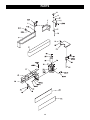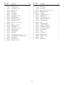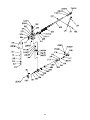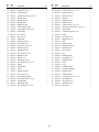
1
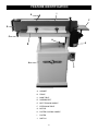
User Manual
Read and understand this manual before using machine.
OSCILLATING EDGE SANDER
Model No.
55230
®
C
US
STEEL CITY TOOL WORKS
Manual Part No. OR73976
VER. 4.07
eel City
s been designed,
ha
er
nd
sa
ge
ed
s
hi
T
.
er
Oscillating Edge Sand
stomer, in mind. When
cu
e
th
u,
yo
ith
w
d
te
ec
tested,and insp
ur edge sander
yo
d,
ne
ai
nt
ai
m
d
an
ed
us
properly assembled,
e free service, which is
bl
ou
tr
of
s
ar
ye
ith
w
u
will provide yo
hinery warranties
ac
m
t
es
ng
lo
e
th
of
e
on
why it is backed by
in the business.
ucts in the Steel
od
pr
y
an
m
of
e
on
st
ju
This edge sander is
hinery and is proof of
ac
m
ng
ki
or
dw
oo
w
of
City’s family
er satisfaction.
om
st
cu
l
ta
to
to
t
en
itm
m
our com
for excellence each and
ve
ri
st
to
ue
in
nt
co
e
w
At Steel City
r customer. For
ou
u,
yo
of
n
io
in
op
e
th
e
every day and valu
Tool Works,
ity
C
l
ee
St
or
er
nd
sa
ge
comments about your ed
toolworks.com .
ty
ci
el
te
.s
w
w
w
at
te
si
please visit our web
hasing your new St
rc
pu
r
fo
U
O
Y
K
N
A
TH
2
TABLE OF CONTENTS
INTRODUCTION
SECTION 1
Warranty .................................................................................................................................................4
SECTION 2
Product Specifications ............................................................................................................................7
SECTION 3
Accessories and Attachments ................................................................................................................7
SECTION 4
Feature Identification ..............................................................................................................................8
SECTION 5
General Safety........................................................................................................................................9
SECTION 6
Product Safety ......................................................................................................................................11
SECTION 7
Electrical Requirements........................................................................................................................12
SECTION 8
Unpacking & Inventory..........................................................................................................................14
SECTION 9
Assembly ..............................................................................................................................................16
SECTION 10
Adjustments ..........................................................................................................................................20
SECTION 11
Operations ............................................................................................................................................23
SECTION 12
Maintenance .........................................................................................................................................24
SECTION 13
Troubleshooting ....................................................................................................................................25
SECTION 14
Parts List...............................................................................................................................................26
INTRODUCTION
This user manual is intended for use by anyone working with this machine. It should be kept available
for immediate reference so that all operations can be performed with maximum efficiency and safety.
Do not attempt to perform maintenance or operate this machine until you have read and understand the
information contained in this manual.
The drawings, illustrations, photographs, and specifications in this user manual represent your machine
at time of print. However, changes may be made to your machine or this manual at any time with no
obligation to Steel City Tool Works.
3
WARRANTY
STEEL CITY TOOL WORKS
5 YEAR LIMITED WARRANTY
Steel City Tool Works, LLC (“SCTW”) warrants all “STEEL CITY TOOL WORKS” machinery to be
free of defects in workmanship and materials for a period of 5 years from the date of the original retail
purchase by the original owner. SCTW will repair or replace, at its expense and at its option, any
SCTW machine, machine part, or machine accessory which in normal use has proven to be defective,
provided that the customer returns the product, shipping prepaid, to an authorized service center with
proof of purchase and provides SCTW with a reasonable opportunity to verify the alleged defect by
inspection. This warranty does not apply to defects due directly or indirectly to misuse, abuse,
negligence, accidents, or lack of maintenance, or to repairs or alterations made or specifically authorized
by anyone other than SCTW. Normal wear components are also excluded under this coverage. Every
effort has been made to ensure that all SCTW machinery meets the highest quality and durability
standards. We reserve the right to change specifications at any time due to our commitment to
continuous improvement of the quality of our products.
EXCEPT AS SET FORTH ABOVE, SCTW MAKES NO EXPRESS OR IMPLIED REPRESENTATIONS OR WARRANTIES WITH RESPECT TO ITS MACHINERY, OR ITS CONDITION,
MERCHANTABILITY, OR FITNESS FOR ANY PARTICULAR PURPOSE OR USE. SCTW
FURNISHES THE ABOVE WARRANTIES IN LIEU OF ALL OTHER WARRANTIES, EXPRESS
OR IMPLIED, INCLUDING THE WARRANTIES OF MERCHANTABILITY AND FITNESS FOR A
PARTICULAR PURPOSE, WHICH ARE HEREBY SPECIFICALLY DISCLAIMED.
SCTW SHALL NOT BE LIABLE FOR ANY (A) SPECIAL, INDIRECT, INCIDENTAL, PUNITIVE
OR CONSEQUENTIAL DAMAGES, INCLUDING WITHOUT LIMITATION LOSS OF PROFITS,
ARISING FROM OR RELATED TO THIS WARRANTY, THE BREACH OF ANY AGREEMENT OR
WARRANTY, OR THE OPERATION OR USE OF ITS MACHINERY, INCLUDING WITHOUT
LIMITATION DAMAGES ARISING FROM DAMAGE TO FIXTURES, TOOLS, EQUIPMENT,
PARTS OR MATERIALS, DIRECT OR INDIRECT LOSS CAUSED BY ANY OTHER PARTY, LOSS
OF REVENUE OR PROFITS, FINANCING OR INTEREST CHARGES, AND CLAIMS BY ANY
THIRD PERSON, WHETHER OR NOT NOTICE OF SUCH POSSIBLE DAMAGES HAS BEEN
GIVEN TO SCTW; (B) DAMAGES OF ANY KIND FOR ANY DELAY BY OR FAILURE OF SCTW
TO PERFORM ITS OBLIGATIONS UNDER THIS AGREEMENT; OR (C) CLAIMS MADE A
SUBJECT OF A LEGAL PROCEEDING AGAINST SCTW MORE THAN ONE (1) YEAR AFTER
SUCH CAUSE OF ACTION FIRST AROSE.
The validity, construction and performance of this Warranty and any sale of machinery by SCTW shall
be governed by the laws of the Commonwealth of Pennsylvania, without regard to conflicts of laws provisions of any jurisdiction. Any action related in any way to any alleged or actual offer, acceptance or
sale by SCTW, or any claim related to the performance of any agreement including without limitation
this Warranty, shall take place in the federal or state courts in Allegheny County, Pennsylvania.
STEEL CITY TOOL WORKS
4
WARRANTY CARD
Name ________________________________________________
Street _______________________________________________
Apt. No. ______________________________________________
City _________________________ State ______ Zip __________
Phone Number_________________________________________
E-Mail ________________________________________________
The following information is given on a voluntary basis
and is strictly confidential.
Where did you purchase your STEEL CITY machine?
Store: ____________________________________________
City:______________________________________________
2.
How did you first learn of Steel City Tool Works?
___ Advertisement
___ Mail Order Catalog
___ Web Site
___ Friend
___ Local Store
! CUT HERE
3.
4.
5.
6.
7.
do you subscribe to?
___ American How-To
___ Family Handyman
___ Fine Woodworking
___ Journal of Light Construction
___ Popular Mechanics
___ Popular Woodworking
___ Old House Journal
___ Popular Science
___ Today’s Homeowner
___ WOOD
___ WOODEN Boat
___ Woodsmith
___ Woodcraft
___ Woodshop News
___ Woodwork
___ Woodworker
___ Workbench
___ Woodworker’s Journal
Other_________________
What is your age group?
___ 20 to 29 years
___ 40 to 49 years
___ 60 to 69 years
How many Steel City machines do you own? _____________
12. Which portable / hand held power tools do you own?
Check all that apply.
___ Belt Sander
___ Biscuit Jointer
___ Dust Collector
___ Circular Saw
___ Detail Sander
___ Drill / Driver
___ Miter Saw
___ Palm Sander
___ Orbital Sander
___ Portable Thickness Planer
___ Saber Saw
___ Router
___ Reciprocating Saw
Other_______________________
13. What machines / accessories would you like to see added to the
STEEL CITY line?
____________________________________________________
____________________________________________________
Which of the following woodworking / remodeling shows do
you watch?
___ Backyard America ___ The American Woodworker
___ Home Time
___ The New Yankee Workshop
___ This Old House
___ Woodwright’s Shop
Other__________________________________________
What is your annual household
___ $20,000 to $29,999
___ $40,000 to $49,999
___ $60,000 to $69,999
___ $80,000 to $89,999
9.
11. Which benchtop tools do you own? Check all that apply.
___ Belt Sander
___ Belt / Disc Sander
___ Drill Press
___ Band Saw
___ Grinder
___ Mini Jointer
___ Mini Lathe
___ Scroll Saw
___ Spindle / Belt Sander
Other______________________
Other_______________________
Which of the following magazines
___ American Woodworker
––– Cabinetmaker
___ Fine Homebuilding
How would you rank your woodworking skills?
___ Simple
___ Intermediate
___ Advance
___ Master Craftsman
10. What stationary woodworking tools do you own?
Check all that apply.
___ Air Compressor
___ Band Saw
___ Drill Press
___ Drum Sander
___ Dust Collection
___ Horizontal Boring Machine
___ Jointer
___ Lathe
___ Mortiser
___ Panel Saw
___ Planer
___ Power Feeder
___ Radial Arm Saw
___ Shaper
___ Spindle Sander
___ Table Saw
___ Vacuum Veneer Press
___ Wide Belt Sander
Other____________________________________________
Product Description:_____________________________________
Model No.: ___________________________________________
Serial No. _____________________________________________
1.
8.
14. What new accessories would you like to see added?
____________________________________________________
____________________________________________________
income?
___ $30,000 to $39,999
___ $50,000 to $59,999
___ 70,000 to $79,999
___ $90,000 +
15. Do you think your purchase represents good value?
___ No
___Yes
16. Would you recommend STEEL CITY products to a friend?
___ No
___ Yes
___ 30 to 39 years
___ 50 to 59 years
___ 70 + years
17. Comments:
____________________________________________________
____________________________________________________
____________________________________________________
____________________________________________________
____________________________________________________
How long have you been a woodworker?
___ 0 to 2 years
___ 2 to 8 years
___ 8 to 20 years
___ over 20 years
5
FOLD ON DOTTED LINE
PLACE
STAMP
HERE
Steel City Tool Works
P.O. Box 10529
Murfreesboro, TN 37129
FOLD ON DOTTED LINE
6
PRODUCT SPECIFICATIONS
Product Specifications
Product Dimensions
Platen size
7" x 33"
Footprint
22" x 17-1/2"
Platen Tilt
0 - 90 degrees
Length
54-1/2"
Main Table size
10" x 30"
Width
18-1/2"
End Table size
9-3/4" x 12"
Height
43-1/2"
Fence size
5" x 23-1/2"
Table Height from floor
38"
Abrasive Belt size
6" x 89"
Weight
270 lbs.
Abrasive Belt speed
3900 SFPM
Abrasive Belt Oscillation Stroke
1/2"
Shipping Dimensions
Abrasive Belt Oscillation Cycle
108 ft./min.
Base
Table Travel
3"
Motor Specifications
Length
62 cm / 24"
Width
49 cm / 19”
Height
66 cm / 26"
Gross weight
19 kg / 42 lbs.
Type
Induction
Horsepower
2 HP
Amps
11
Voltage
230
Length
126 cm / 50"
Phase
Single
Width
67 cm / 26"
Hertz
60
Height
52.5 cm / 21"
RPM
3450
Gross weight
165 kg / 364 lbs.
Sander
ACCESSORIES AND ATTACHMENTS
There are a variety of accessories available for your Steel City Product. For more information on
any accessories associated with this and other machines, please contact your nearest Steel City
distributor, or visit our website at: www.steelcitytoolworks.com.
7
FEATURE IDENTIFICATION
I
E
F
D
C
H
G
B
A
J
A. CABINET
B. FENCE
C. MAIN TABLE
D. SANDING BELT
E. BELT TENSION HANDLE
F.
EXTENSION TABLE
G. MOTOR
H. PLATEN LOCKING HANDLE
I.
PLATEN
J.
SWITCH
8
GENERAL SAFETY
!
WARNING
!
WARNING
TO AVOID serious injury and damage to the machine,
read and follow all Safety and Operating Instructions
before assembling and operating this machine.
This manual is not totally comprehensive. It does not
and can not convey every possible safety and operational problem which may arise while using this
machine. The manual will cover many of the basic and
specific safety procedures needed in an industrial environment.
Exposure to the dust created by power sanding, sawing, grinding, drilling and other construction activities
may cause serious and permanent respiratory or
other injury, including silicosis (a serious lung disease), cancer, and death. Avoid breathing the dust,
and avoid prolonged contact with dust. The dust
may contain chemicals known to the State of
California to cause cancer, birth defects or other
reproductive harm.
All federal and state laws and any regulations having
jurisdiction covering the safety requirements for use of
this machine take precedence over the statements in
this manual. Users of this machine must adhere to all
such regulations.
Some examples of these chemicals are:
• Lead from lead-based paints.
Below is a list of symbols that are used to attract your
attention to possible dangerous conditions.
• Crystalline silica from bricks, cement and other
masonry products.
• Arsenic and chromium from chemically-treated
lumber.
!
This is the international safety alert symbol. It is used
to alert you to potential personal injury hazards. Obey
all safety messages that follow this symbol to avoid
possible injury or death.
!
Always operate tool in well ventilated area and provide for proper dust removal. Use a dust collection
system along with an air filtration system whenever
possible. Always use properly fitting NIOSH/OSHA
approved respiratory protection appropriate for the
dust exposure, and wash exposed areas with soap
and water.
DANGER
Indicates an imminently hazardous situation which, if
not avoided, WILL result in death or serious injury.
!
1. To avoid serious injury and damage to the machine,
read the entire User Manual before assembly and
operation of this machine.
WARNING
Indicates a potentially hazardous situation which, if not
avoided, COULD result in death or serious injury.
!
CAUTION
!
WARNING
Indicates a potentially hazardous situation, if not avoided, MAY result in minor or moderate injury. It may also
be used to alert against unsafe practices.
CAUTION
2. ALWAYS wear eye protection. Any machine can
throw debris into the eyes during operations,
which could cause severe and permanent eye
damage. Everyday eyeglasses are NOT safety
glasses. ALWAYS wear Safety Goggles (that
comply with ANSI standard Z87.1) when operating power tools.
CAUTION used without the safety alert symbol indicates a potentially hazardous situation which, if not
avoided, may result in property damage.
NOTICE
This symbol is used to alert the user to useful information about proper operation of the machine.
9
!
11. DO NOT FORCE the machine to perform an operation for which it was not designed. It will do a safer
and higher quality job by only performing operations
for which the machine was intended.
WARNING
12. DO NOT stand on a machine. Serious injury could
result if it tips over or you accidentally contact any
moving part.
3. ALWAYS wear hearing protection. Plain cotton is
not an acceptable protective device. Hearing
equipment should comply with ANSI S3.19
Standards.
!
13. DO NOT store anything above or near the machine.
14. DO NOT operate any machine or tool if under the
influence of drugs, alcohol, or medication.
WARNING
15. EACH AND EVERY time, check for damaged parts
prior to using any machine. Carefully check all
guards to see that they operate properly, are not
damaged, and perform their intended functions.
Check for alignment, binding or breakage of all
moving parts. Any guard or other part that is damaged should be immediately repaired or replaced.
4. ALWAYS wear a NIOSH/OSHA approved dust
mask to prevent inhaling dangerous dust or airborne particles.
16. Ground all machines. If any machine is supplied
with a 3-prong plug, it must be plugged into a 3contact electrical receptacle. The third prong is
used to ground the tool and provide protection
against accidental electric shock. DO NOT remove
the third prong.
5. ALWAYS keep the work area clean, well lit, and
organized. DO NOT work in an area that has slippery floor surfaces from debris, grease, and wax.
6. ALWAYS unplug the machine from the electrical
receptacle before making adjustments, changing
parts or performing any maintenance.
17. Keep visitors and children away from any machine.
DO NOT permit people to be in the immediate work
area, especially when the machine is operating.
7. AVOID ACCIDENTAL STARTING. Make sure that
the power switch is in the “OFF” position before
plugging in the power cord to the electrical
receptacle.
!
18. KEEP protective guards in place and in working
order.
19. MAINTAIN your balance. DO NOT extend yourself
over the tool. Wear oil resistant rubber soled shoes.
Keep floor clear of debris, grease, and wax.
WARNING
20. MAINTAIN all machines with care. ALWAYS KEEP
machine clean and in good working order. KEEP all
blades and tool bits sharp.
8. AVOID a dangerous working environment. DO
NOT use electrical tools in a damp environment
or expose them to rain or moisture.
!
21. NEVER leave a machine running, unattended. Turn
the power switch to the OFF position. DO NOT
leave the machine until it has come to a complete
stop.
22. REMOVE ALL MAINTENANCE TOOLS from the
immediate area prior to turning the machine ON.
WARNING
23. SECURE all work. When it is possible, use clamps
or jigs to secure the workpiece. This is safer than
attempting to hold the workpiece with your hands.
9. CHILDPROOF THE WORKSHOP AREA by
removing switch keys, unplugging tools from the
electrical receptacles, and using padlocks.
24. STAY ALERT, watch what you are doing, and use
common sense when operating any machine. DO
NOT operate any machine tool while tired or under
the influence of drugs, alcohol, or medication. A
moment of inattention while operating power tools
may result in serious personal injury.
10. DO NOT use electrical tools in the presence of
flammable liquids or gasses.
10
29. Information regarding the safe and proper operation
of this tool is also available from the following
sources:
25. USE ONLY recommended accessories. Use of
incorrect or improper accessories could cause serious injury to the operator and cause damage to the
machine. If in doubt, DO NOT use it.
Power Tool Institute
1300 Summer Avenue
Cleveland, OH 44115-2851
www.powertoolinstitute.org
26. THE USE of extension cords is not recommended
for 230V equipment. It is better to arrange the
placement of your equipment and the installed
wiring to eliminate the need for an extension cord.
If an extension cord is necessary, refer to the chart
in the Grounding Instructions section to determine
the minimum gauge for the extension cord. The
extension cord must also contain a ground wire and
plug pin.
National Safety Council
1121 Spring Lake Drive
Itasca, IL 60143-3201
American National Standards Institute
25West 43rd. St, 4th Floor
New York, NY. 10036
ANSI 01.1 Safety Requirements
For Woodworking Machines
WWW.ANSI.ORG
27. Wear proper clothing, DO NOT wear loose clothing,
gloves, neckties, or jewelry. These items can get
caught in the machine during operations and pull
the operator into the moving parts. Users must
wear a protective cover on their hair, if the hair is
long, to prevent it from contacting any moving parts.
U.S. Department of Labor Regulations
OSHA 1910.213 Regulations
WWW.OSHA.GOV
28. SAVE these instructions and refer to them frequently and use them to instruct other users.
PRODUCT SAFETY
6. Safety decals are on this machine to warn and
direct you to how to protect yourself or visitors from
personal injury. These decals MUST be maintained
so that they are legible. REPLACE decals that are
not legible.
1. Serious personal injury may occur if normal safety
precautions are overlooked or ignored. Accidents
are frequently caused by lack of familiarity or failure
to pay attention. Obtain advice from supervisor,
instructor, or another qualified individual who is
familiar with this machine and its operations.
7. DO NOT leave the unit plugged into the electrical
outlet. Unplug the unit from the outlet when not in
use and before servicing, performing maintenance
tasks, or cleaning.
2. Every work area is different. Always consider safety first, as it applies to your work area. Use this
machine with respect and caution. Failure to do so
could result in serious personal injury and damage
to the machine.
8. ALWAYS turn the power switch “OFF” before
unplugging the oscillating edge sander.
3. Prevent electrical shock. Follow all electrical and
safety codes, including the National Electrical Code
(NEC) and the Occupational Safety and Health
Regulations (OSHA). All electrical connections and
wiring should be made by qualified personnel only.
!
!
WARNING
WARNING
9. DO NOT handle the plug or oscillating edge
sander with wet hands.
10. USE accessories only recommended by Steel City.
4. TO REDUCE the risk of electrical shock. DO
NOT use this machine outdoors. DO NOT
expose to rain or moisture. Store indoors in a
dry area.
11. DO NOT pull the oscillating edge sander by the
power cord. NEVER allow the power cord to come
in contact with sharp edges, hot surfaces, oil or
grease.
5. STOP using this machine, if at any time you experience difficulties in performing any operation.
Contact your supervisor, instructor or machine service center immediately.
12. DO NOT unplug the oscillating edge sander by
pulling on the power cord. ALWAYS grasp the plug,
not the cord.
11
20. ALWAYS inspect the workpiece for nails, staples,
knots, and other imperfections that could be dislodged and thrown from the machine during sanding
operations.
13. REPLACE a damaged cord immediately. DO NOT
use a damaged cord or plug. DO NOT use if the
oscillating edge sander is not operating properly, or
has been damaged, left outdoors or has been in
contact with water.
21. NEVER operate the sander without an adequate
dust collection system in place and running.
14. DO NOT use the oscillating edge sander as a toy.
DO NOT use near or around children.
22. NEVER sand tapered or pointed stock with the point
facing the feed direction.
15. ALWAYS wear eye protection. The operation of any
edge sander can result in debris being thrown into
your eyes, causing severe eye damage. Everyday
glasses are not safety glasses. Wear safety glasses
that comply with ANSI standard Z87.1
23. ALWAYS disconnect the machine from the power
source before changing the abrasive belt or performing any cleaning and/ or maintenance tasks.
24. ALWAYS feed the workpiece against the rotation of
the sanding surface.
16. DO NOT jam the workpiece against the sanding
surfaces. Use both hands to grasp the workpiece
and ease it against the belt using light pressure.
25. NEVER wear gloves or loose clothing when sanding. NEVER hold the workpiece with a rag when
sanding.
17. DO NOT place hands near, or in contact with,
sanding surfaces during operation.
26. NEVER start the machine with the workpiece
against the sanding surface.
18. ALWAYS use two hands to grasp the workpiece.
19. NEVER sand more than one piece of stock at a
time.
27. NEVER start the machine before clearing the table
of all objects (tools, scrap pieces, etc.).
ELECTRICAL REQUIREMENTS
!
WARNING
The switch provided with your edge sander is designed
for 230 volt single phase usage only. The switch has a
plug that is designed to plug into a 230 volt outlet.
There are many different configurations for 230 volt
outlets, so it is conceivable that the configuration of the
plug may not match the configuration of your existing
outlet. If this is the case, you will have to replace the
plug with a UL/CSA approved plug that matches the
configuration of your 230V outlet.
To reduce the risk of electric shock, follow all electrical and safety codes, including the National Electric
Code (NEC) and the Occupational Safety and Health
Regulations (OSHA). All electrical connections and
wiring should be made by qualified personnel only.
12
GROUNDING INSTRUCTIONS
!
The motor supplied with your machine is a 230 volt,
60 hertz, single phase motor. Never connect the green
or ground wire to a live terminal.
WARNING
A machine with a 230 volt plug should only be connected to an outlet having the same configuration as the plug.
This machine MUST BE GROUNDED while in use to
protect the operator from electric shock.
EXTENSION CORDS
In the event of a malfunction or breakdown, GROUNDING provides the path of least resistance for electric
current and reduces the risk of electric shock. The plug
MUST be plugged into a matching electrical receptacle
that is properly installed and grounded in accordance
with ALL local codes and ordinances.
!
WARNING
To reduce the risk of fire or electrical shock, use the
proper gauge of extension cord. When using an
extension cord, be sure to use one heavy enough to
carry the current your machine will draw.
If a plug is provided with your machine DO NOT modify
the plug. If it will not fit your electrical receptacle, have
a qualified electrician install the proper connections to
meet all electrical codes local and state. All connections
must also adhere to all of OSHA mandates.
The smaller the gauge-number, the larger the diameter
of the extension cord is. If in doubt of the proper size of
an extension cord, use a shorter and thicker cord. An
undersized cord will cause a drop in line voltage resulting in a loss of power and overheating.
IMPROPER ELECTRICAL CONNECTION of the equipment-grounding conductor can result in risk of electric
shock. The conductor with the green insulation (with or
without yellow stripes) is the equipment-grounding conductor. DO NOT connect the equipment-grounding conductor to a live terminal.
!
Check with a qualified electrician or service personnel if
you do not completely understand the grounding
instructions, or if you are not sure the tool is properly
grounded.
CAUTION
USE ONLY a 3-wire extension cord that has a 3-prong
grounding plug and a 3-pole receptacle that accepts the
machine’s plug.
If you are using an extension cord outdoors, be sure it
is marked with the suffix “W-A” (“W” in Canada) to indicate that it is acceptable for outdoor use.
Make certain the extension cord is properly sized, and
in good electrical condition. Always replace a worn or
damaged extension cord immediately or have it
repaired by a qualified person before using it.
PLUGS/RECEPTACLES
!
WARNING
Protect your extension cords from sharp objects,
excessive heat, and damp or wet areas.
• Electrocution or fire could result if this machine is
not grounded properly or if the electrical configuration does not comply with local and state electrical
codes.
• MAKE CERTAIN the machine is disconnected
from power source before starting any electrical
work.
• MAKE SURE the circuit breaker does not exceed
the rating of the plug and receptacle.
MINIMUM RECOMMENDED GAUGE FOR EXTENSION CORDS (AWG)
230 VOLT OPERATION ONLY
13
25’ LONG
50’ LONG
100’ LONG
0 to 6 Amps
16 AWG
16 AWG
14 AWG
6 to 8 Amps
16 AWG
16 AWG
12 AWG
8 to 12 Amps
14 AWG
14 AWG
10 AWG
12 to 15 Amps
12 AWG
12 AWG
10 AWG
15 to 20 Amps
10 AWG
10 AWG
Not
recommended
UNPACKING & INVENTORY
!
tective coatings can be removed by spraying WD-40 on
them and wiping it off with a soft cloth. This may need
redone several times before all of the protective coatings are removed completely.
WARNING
After cleaning, apply a good quality paste wax to any
unpainted surfaces. Make sure to buff out the wax
before assembly.
• The machine is heavy, two people are required to
unpack and lift.
Compare the items to inventory figures; verify that all
items are accounted for before discarding the shipping
box.
• Use a safety strap to avoid tip over when lifting
machine.
Check shipping carton and machine for damage before
unpackaging. Carefully remove packaging materials,
parts and machine from shipping carton. Always check
for and remove protective shipping materials around
motors and moving parts. Lay out all parts on a clean
work surface.
!
WARNING
If any parts are missing, do not attempt to plug in the
power cord and turn “ON” the machine. The machine
should only be turned “ON” after all the parts have been
obtained and installed correctly. For missing parts,
contact Steel City at 1-877-SC4-TOOL.
Remove any protective materials and coatings from all
of the parts and the oscillating edge sander. The pro-
A
M
N
G
B
J
D
C
K
E
F
H
L
A. Adjustment Tool
E. 5/16" Lock Washer (2)
K. 1/4-20 x 1/2" Soc Hd Scr (2)
B. Workpiece Rest Lock Knob
F.
L. 1/4" Flat Washer (2)
C. Belt Tension Handle
G. Fence Lock knobs (2)
M. Fence
D. 5/16"-18 x 1-1/4" Bolt (2)
H. T-Nuts (2)
N. Switch
J.
5/16" Flat Washer (2)
5/16" Flat Washer (3)
14
P. Feet (4)
Q. 5/16-18 x 5/8"
Screw (4)
P
R. 5/16" Flat Washer
(4)
S. 5/16-18 Hex Nut
(4)
T.
3/16-24 x 3/8"
Soc Hd. Scr (2)
Q
U. Extension Table
Mounting Bracket
R
S
U
T
V. Workpiece Support
W. 3/16-24 x 1/4"
Screw (3)
Y
X. Motor Drum Guard
X
Y. Miter Gauge
Z. Extension Table
Z
W
V
15
ASSEMBLY
!
1. Turn cabinet upright.
WARNING
2. Have two or more people help lift the sander (D)
and place it squarely on the cabinet. SEE FIG. 2
MAKE CERTAIN MACHINE IS DISCONNECTED
FROM THE POWER SOURCE.
Fig. 2
CABINET ASSEMBLY
!
WARNING
MAKE CERTAIN THE MACHINE IS DISCONNECTED
FROM THE POWER SOURCE.
D
1. Turn cabinet (A) upside down. SEE FIG. 1.
Fig. 1
E
E
A
B
B
3. Align the two holes (E) on the sides of the cabinet
with the two holes on the base of the sander.
C
B
4. Attach the sander to the cabinet using two 5/16-18
x 1/1-4"bolts, two 5/16" lock washers and two 5/16"
flat washers. Tighten hardware.
SWITCH
!
WARNING
2. Install 4 feet (B) using four 5/16-18 x 5/8" screws,
four 5/16 flat washers, and four 5/16-18 nuts (C).
MAKE CERTAIN THE MACHINE IS DISCONNECTED
FROM THE POWER SOURCE.
NOTE: Make sure to align the two tabs on the feet with
the holes in the cabinet.
Fig. 3
3. Tighten all hardware.
G
SANDER TO CABINET
!
WARNING
MAKE CERTAIN THE MACHINE IS DISCONNECTED
FROM THE POWER SOURCE.
!
F
WARNING
1. Mount the switch (F) to the right side of the cabinet
using two 1/4-20 x 1/2" Soc Hd Scrs. and two 1/4"
flat washers (G). SEE FIG. 3.
• The machine is heavy, two people are required to
unpack and lift.
• Use a safety strap to avoid tip over when lifting
machine.
2. Connect the switch cord to the motor cord.
16
EXTENSION TABLE
!
BELT TENSIONING HANDLE
WARNING
!
WARNING
MAKE CERTAIN THE MACHINE IS DISCONNECTED
FROM THE POWER SOURCE.
MAKE CERTAIN THE MACHINE IS DISCONNECTED
FROM THE POWER SOURCE.
NOTE: The motor drum guard must be moved to the
side or removed completely to install the extension
table.
1. Using a rubber mallet tap the handle (M) onto the
belt tensioning shaft (N). SEE FIG. 5.
1. Mount the Extension table mounting bracket (H) to
the right side of the motor using Two Soc Hd Scrs
(J). SEE FIG. 4.
Fig. 5
M
Fig. 4
N
K
J
L
H
J
2. Insert the shaft of the extension table (K) into the
mounting bracket (H).
3. Install the lock knob (L) and tighten to hold the
extension table (K) in place.
NOTE: Make certain to maintain the gap between the
motor drum and the extension table to prevent the belt
from contacting the table.
17
INSTALLING THE BELT
!
INSTALLING THE WORKPIECE
SUPPORT
WARNING
!
MAKE CERTAIN THE MACHINE IS DISCONNECTED
FROM THE POWER SOURCE.
WARNING
MAKE CERTAIN THE MACHINE IS DISCONNECTED
FROM THE POWER SOURCE.
1. Loosen the two lock knobs (A) on the rear of the
belt guard (B). Remove the belt guard (B).
SEE FIG. 6.
1. Insert the pin (F) of the workpiece support (G) into
the hole in the top of the sander. SEE FIG. 8.
Fig. 6
Fig. 8
VIEW FROM REAR
OF MACHINE
B
C
H
A
F
G
2. Make sure the belt tension handle (C) is in the loose
position.
3. Install the belt (D) over the two drums (E) making
sure that the entire belt is on the drums.
SEE FIG. 7.
Fig. 7
E
D
2. Thread the lock knob (H) into the tapped hole.
E
3. Adjust the workpiece support (G) so that it is as
close as possible to the sanding belt without
touching it.
VIEW FROM REAR
OF MACHINE
NOTE: Make certain that the directional arrows on the
inside of the belt face the direction the belt will travel
when installed.
4. Move the belt tensioning handle (C) to the tighten
position making sure the entire belt (D) is on the
drums. SEE FIG. 6.
5. Reinstall the belt guard (B) and tighten the lock
knobs (A).
18
INSTALLING THE
MOTOR DRUM GUARD
!
INSTALLING THE FENCE
!
WARNING
WARNING
MAKE CERTAIN THE MACHINE IS DISCONNECTED
FROM THE POWER SOURCE.
MAKE CERTAIN THE MACHINE IS DISCONNECTED
FROM THE POWER SOURCE.
1. Slide the two T-nuts (A) into the miter slot (B) in the
main table. SEE FIG. 10.
NOTE: The motor drum guard will have to be positioned
to the rear of the sander while the workpiece support or
the extension table is installed.
Fig. 10
1. Place the motor drum guard (A) over the dust chute
(B). SEE FIG. 9.
Fig. 9
D
C
D
B
A B
C
A
2. Place the fence (C) over top of the T-nuts.
3. Install one 5/16" flat washer on each of the lock
knobs (D), and thread the knobs into the T-nuts.
D
4. Position the fence in the desired location and tighten
the lock knobs.
2. Install three 3/16-24 x 1/4" screws (C) and tighten.
3. The edge sander is also equipped with a 4in.
dust port (D) that should be connected to a dust
collector.
19
ADJUSTMENTS
TILTING SANDER PLATEN
!
ADJUSTING SANDER PLATEN
POSITIVE STOPS
WARNING
!
MAKE CERTAIN THE MACHINE IS DISCONNECTED
FROM THE POWER SOURCE.
WARNING
MAKE CERTAIN THE MACHINE IS DISCONNECTED
FROM THE POWER SOURCE.
The platen (E) is the perfectly flat steel plate that has
the graphite covering on it. The platen is the surface the
sanding belt runs against.
The sander platen has positive stops for both 90 Deg.
and 180 Deg. These positive stops should be set at the
factory. It is still a good idea to familiarize yourself with
the following procedures.
The sander platen can be positioned between 90 Deg.
and 180 Deg.
1. The 90 Deg. positive stops (F) can be adjusted by
loosening the lock nut and threading the set screws
in or out. SEE FIG. 12.
To adjust platen angle:
1. Loosen platen locking lever (A). SEE FIG. 11.
Fig. 12
Fig. 11
VIEW FROM REAR
OF MACHINE
E
C
F
D B
A
2. Retighten the lock nut after adjustment is made
making sure the set screw does not move.
2. Tilt platen (E) to desired angle.
3. The 180 Deg. positive stops (G) can be adjusted by
loosening the lock nut and threading the bolts in or
out. SEE FIG. 13.
3. Retighten platen locking lever (A).
Fig. 13
ADJUSTING MAIN TABLE
!
WARNING
VIEW FROM REAR
OF MACHINE
MAKE CERTAIN THE MACHINE IS DISCONNECTED
FROM THE POWER SOURCE.
WARNING: Do not position the main table below the
sanding belt. Set at an overlap of at least 1/16". Failure
to comply may cause serious injury!
The main table height and angle can be adjusted.
To adjust main table:
1. Loosen locking handle (B) and lock knob (C).
SEE FIG. 11.
G
2. Move main table (D) to desired height and/or angle.
3. Retighten locking lever (B) and lock knob (C).
4. Retighten the lock nut after adjustment is made
making sure the bolt does not move.
20
ADJUSTING BELT TRACKING
!
ADJUSTING MOTOR MOUNTING
TRACKING
WARNING
!
MAKE CERTAIN THE MACHINE IS DISCONNECTED
FROM THE POWER SOURCE.
WARNING
MAKE CERTAIN THE MACHINE IS DISCONNECTED
FROM THE POWER SOURCE.
The belt tracking may need to be adjusted when
installing or replacing a belt.
Motor mount tracking is a coarse adjustment. Use the
adjusting belt tracking section first.
To adjust the belt tracking:
1. Loosen lock knob (H). SEE FIG.14.
If proper tracking can not be achieved then use this
procedure. To adjust the motor mount tracking:
Fig. 14
1. Loosen the four motor mounting bolts, two of which
are shown at (L). SEE FIG. 15.
Fig. 15
VIEW FROM
REAR OF
MACHINE
VIEW FROM REAR
OF MACHINE
K
L
H
M
N
J
2. Install the adjustment tool (J) into one of the holes in
the eccentric (K).
3. Use your hand to move the belt and observe the
movement of the sanding belt on the drums.
NOTE: The belt should remain near the center of the
drums.
2. Loosen the two motor tracking lock nuts (M).
3. Turn one motor tracking bolt (N) in a 1/4 turn and
rotate the belt by hand. Observe the direction the
adjustment is causing the belt to track. If the belt
has moved in the correct direction go to step 5.
4. To adjust the belt tracking up, turn the eccentric
clockwise.
5. To adjust the belt tracking down, turn the eccentric
counter clockwise.
4. If the belt tracked the wrong direction, back the
motor tracking bolt (N) to its starting position. Turn
the other motor tracking bolt (N) in 1/4 turn and
rotate the belt by hand. This should change the belt
tracking to the proper direction.
6. After proper belt tracking is achieved, remove
adjusting tool (J) and retighten lock knob (H).
5. Tighten both motor tracking lock nuts (M) making
sure the motor tracking bolts (N) do not move. Then
tighten the motor mounting nuts (L). Return to the
Adjusting Belt Tracking section to finish the fine
adjustments to the belt tracking.
21
ADJUSTING THE
MOTOR DRUM GUARD
!
WARNING
MAKE CERTAIN THE MACHINE IS DISCONNECTED
FROM THE POWER SOURCE.
1. To move the motor drum guard (A), loosen the two
lock knobs (B). SEE FIG. 16.
Fig. 16
B
A
2.
Reposition the motor drum guard.
3. Retighten the two lock knobs.
22
OPERATIONS
!
VERTICAL SANDING
WARNING
For vertical sanding, the platen must be locked in the
vertical (90Deg.) position.
NEVER OPERATE THE EDGE SANDER WITHOUT
PROPERLY INSTALLED BELT GUARDS. FAILURE TO
COMPLY MAY CAUSE SERIOUS INJURY.
The main table (A) can be raised or lowered to fully
utilize the entire belt. Refer to the adjustments section
of this manual. You may install the workpiece support
and use the miter gauge (not shown) in this position.
SEE FIG. 18.
BEFORE STARTING THE EDGE SANDER, BE SURE
YOU HAVE FOLLOWED ALL THE GUIDELINES FOR
SET UP AND SAFETY.
• Connect the Edge Sander to the power source and
push the start button.
Fig. 18
• Make sure the belt tracks properly. Refer to the adjustment section of this manual if required.
A
• It is recommended to use a scrap piece of wood to
help get the feel of the machine.
• Always make sure that any wood you use is free of
defects and foreign objects.
HORIZONTAL SANDING
For horizontal sanding, the platen must be locked in the
horizontal (180 Deg.) position. Install and secure the
fence (A) and the workpiece support (B). SEE FIG. 17.
CONTOUR SANDING
Fig. 17
For contour sanding, the platen must be locked in the
vertical (90Deg) position and the extension table must
be installed on the motor mount. See installing the
extension table in the assembly section of this manual.
A
B
The extension table (A) can be raised or lowered to fully
utilize the entire belt. Make certain the motor drum
guard (C) is positioned out of the way and the two lock
knobs (B) are tightened. SEE FIG. 19.
Fig. 19
C
B
A
NOTE: When not using the extension table it should be
removed and the motor drum guard should be secured
over the motor drum to prevent accidental contact.
23
MAINTENANCE
GEAR BOX:
Your Edge Sander requires little maintenance. Cleaning
will increase the machine’s efficiency by removing grime
which can gum up moving parts. If you find that the
machine sands less efficiently than usual, inspect the
sanding belt and clean with a gum rubber belt cleaner
or replace as needed. An occasional application of
good quality paste wax (one that does not contain silicone or other synthetics) will keep the sander tables
and other bare metal parts from rusting.
!
!
WARNING
MAKE CERTAIN THAT THE MACHINE IS DISCONNECTED FROM THE POWER SOURCE.
Periodically lubricate the gears in the gear box using a
quality #2 grease or equivalent.
WARNING
MAKE CERTAIN THE MACHINE IS DISCONNECTED
FROM THE POWER SOURCE.
SANDING BELTS:
Sanding belts should be inspected periodically for wear
or damage. Damaged belts should be replaced before
further use.
BEARINGS:
The sander features factory sealed bearings that
requires no lubrication during its lifetime.
Should a bearing fail, your sander will develop a noticeable rumble, which will increase when the machine is
put under load. Bearings must be replaced when this
occurs.
24
TROUBLESHOOTING GUIDE
To prevent injury to yourself or damage to the edge sander, turn the switch to the OFF position and unplug the power
cord from the electrical receptacle before making any adjustments.
PROBLEM
LIKELY CAUSE(S)
SOLUTION
Motor will not
start.
1. Low or no voltage.
1. Check power line for proper voltage.
2. Open circuit in motor or loose
connections.
2. Inspect all lead connections on motor for loose or open
connections.
Motor will not start;
fuses or circuit
breakers blow.
1. Short circuit in line cord or plug.
1. Inspect cord or plug for damaged insulation and
shorted wires.
2. Short circuit in motor or loose
connections.
2. Inspect all connections on motor for loose or shorted
terminals or worn insulation.
3. Incorrect fuses or circuit breakers in
power line.
3. Install correct fuses or circuit breakers.
Motor fails to
develop full power
(power output of
motor decreases
rapidly with
decrease in voltage
at motor terminals).
1. Power line overloaded with lights,
appliances, and other motors.
1. Reduce load on power line.
Motor overheats.
2. Undersized wires or circuits too long.
2. Increase wire sizes or reduce length of wire.
3. General overloading of power company
facilities.
3. Request a power check from the power company.
1. Motor overloaded.
1. Reduce load on motor.
2. Air circulation through the motor
restricted.
2. Clean out motor to provide normal air circulation.
1. Short circuit in motor or loose
connections.
1. Inspect connections on motor for loose or shorted
terminals or worn insulation.
2. Low voltage.
2. Correct the low voltage conditions.
3. Incorrect fuses or circuit breakers in
power line.
3. Install correct fuses or circuit breakers.
4. Motor overloaded.
4. Reduce load on motor.
Machine slows
when operating.
1. Applying too much pressure to
workpiece.
1. Reduce feed pressure. Never force workpiece into
sanding belt.
Sanding belt keeps
tearing.
1. Belt is running in the wrong direction.
1. Turn belt so the arrows on the inside of the belt are
pointing in the direction the belt is traveling.
Sanding edge is
not square.
1. Platen is not square to the table.
1. Use a square to adjust the platen to the table.
Sanding marks on
the wood.
1. Wrong grit sanding belt.
1. Use a finer grit belt.
2. Feed pressure too great.
2. Reduce feed pressure. Never force workpiece into
sanding belt.
3. Sanding against the grain.
3. Sand with the grain.
Motor stalls
(resulting in blown
fuses or tripped
circuit).
25
PARTS
26
KEY
NO.
PART
NO.
DESCRIPTION
1
OR73890
BELT GUARD
1
30
OR73904
MOTOR SANDING DRUM
1
2
OR90064
WASHER FLAT 5/16”
2
31
OR73905
RESET SWITCH
1
3
OR73891
LOCK KNOB M8 x 12mm
2
36
OR94455
KEY 5x5x25mm
1
4
OR90680
WASHER FLAT 1/4”
4
37
OR70416
MOTOR ASSY INC: Ref. 31,37A,37B
1
5
OR73892
LINK PLATE
1
37A
OR70363
MOTOR SPEC PLATE
1
6
OR73893
LOCK KNOB M6
2
37B
OR73906
CAPACITOR
1
KEY
NO.
QTY.
PART
NO.
DESCRIPTION
QTY.
7
OR73894
DUST CHUTE
1
38
OR94392
SCR HEX HD 5/16-18 x 1-1/4”
4
8
OR73895
LOCK KNOB M8 x 35mm
1
39
OR90064
WASHER FLAT 5/16”
4
9
OR90064
WASHER FLAT 5/16”
1
40
OR92720
SCR FLAT HD M5 x 12mm
8
10
OR94999
SCR PAN HD 3/16-24 x 1/4”L
1
41
OR90689
WASHER EXT TOOTH 3/16”
8
11
OR73896
MOTOR DRUM GUARD
1
42
OR73907
DIRECTIONAL LABEL
1
12
OR94999
SCR PAN HD 3/16-24 x 1/4”L
2
43
OR73908
LABEL
1
13
OR73897
PIN
1
44
OR73909
SANDING PLATFORM
1
14
OR73898
WORKPIECE SUPPORT
1
45
OR90689
WASHER EXT TOOTH 3/16”
1
15
OR73899
SANDING BELT
1
46
OR95001
SCR FLAT HD 3/16-24 x 3/4”
1
21
OR94392
SCR HEX HD 5/16-18 x 1-1/4”
1
47
OR73910
SCALE ASSY INC: REF. 48,49
1
22
OR90064
WASHER FLAT 5/16”
1
48
OR73911
SCALE BRACKET
1
23
OR73900
EXTENSION TABLE
1
49
OR73912
SCALE
1
24
OR73901
LOCK KNOB
1
50
OR90338
NUT HEX 5/16-18
4
25
OR95000
SCR HEX SOC HD 3/16” x 3/8”
2
51
OR91658
WASHER LOCK 5/16”
4
26
OR73902
EXTENSION TABLE MOUNTING BRACKET
1
52
OR90064
WASHER FLAT 5/16”
4
27
OR73903
SUPPORT ROD
1
53
OR73913
PLATEN
1
28
OR91330
SCR HEX HD 1/4-20 x 1”
1
54
OR73914
GRAPHITE PAD
1
29
OR90680
WASHER FLAT 1/4” x 23”
1
27
28
KEY
NO.
PART
NO.
DESCRIPTION
QTY.
KEY
NO.
PART
NO.
DESCRIPTION
QTY.
100
OR95002
SCR ROUND HD 3/16-24 x 1/4”
4
138
OR93903
NUT NYLOK M5
4
101
OR95003
WASHER LOCK 3/16”
4
141
OR95008
SCR HEX SOC HD 5/16” x 1-1/4”
1
102
OR73915
DRUM BRACKET
1
142
OR91658
WASHER LOCK 5/16”
2
103
OR73916
DRUM ASSY INC: REF. 104 thru 115
1
143
OR90064
WASHER FLAT 5/16”
2
104
OR73917
BEARING SEAT
1
144
OR73928
BRACKET
1
105
OR90075
BEARING 6202ZZ
1
145
OR90680
WASHER FLAT 1/4”
2
106
OR73918
BEARING SEAT
1
146
OR90070
WASHER LOCK 1/4”
2
107
OR90075
BEARING 6202ZZ
1
148
OR95009
SCR HEX SOC HD 1/4-20 x 1/2”
2
108
OR73919
IDLER SANDING DRUM
1
150
OR73929
GEAR BOX ASSY INC: REF. 151 thru 162
1
109
OR90239
SCR HEX SOC SET M6 x 6mm
2
151
OR73930
FOAM GASKET
1
110
OR73920
DRUM SHAFT
1
152
OR95010
SCR HEX SOC HD M5 x 30mm
2
111
OR95004
KEY 5x5x40mm
1
153
OR73931
COVER
1
112
OR95005
KEY 4x4x25mm
1
154
OR94480
NUT NYLOK 5/16-18
1
113
OR73921
WORM GEAR
1
155
OR90064
WASHER FLAT 5/16”
1
114
OR90064
WASHER FLAT 5/16”
1
156
OR73932
GEAR
1
115
OR94480
NUT NYLOK 5/16-18
1
157
OR95011
BEARING 6011ZZ
1
120
OR95006
SCR FLAT HD 1/4-20 x 3/4”
3
158
OR73933
GEAR BOX HOUSING
1
121
OR90064
WASHER FLAT 5/16”
1
159
OR95011
BEARING 6011ZZ
1
122
OR91658
WASHER LOCK 5/16”
1
160
OR95012
KEY 4x4x15mm
1
123
OR90634
SCR HEX HD 5/16-18 x 1”
1
161
OR73934
CAM
1
124
OR95007
BEARING 6003ZZ
1
162
OR95013
BEARING 6800ZZ
1
125
OR73922
BEARING CUP
1
163
OR94480
NUT NYLOK 5/16-18
1
126
OR95003
WASHER LOCK 3/16”
4
164
OR95013
BEARING 6800ZZ
1
127
OR95002
SCR ROUND HD 3/16-24 x 1/4”
4
165
OR73935
SHAFT
1
128
OR73923
SPRING
1
166
OR95014
C Ring
2
129
OR73924
TENSION BAR
1
167
OR73936
ECCENTRIC DRUM
1
130
OR73925
LEVER
1
168
OR73937
ECCENTRIC BRACKET
1
131
OR90064
WASHER FLAT 5/16”
1
169
OR90680
WASHER FLAT1/4”
2
132
OR94480
NUT NYLOK 5/16-18
1
170
OR90070
WASHER LOCK 1/4”
2
133
OR73926
BELT TENSION HANDLE
1
171
OR95014
SCR HEX SOC HD 1/4-20 x 1-1/4”
2
134
OR90588
SCR HEX SOC HD M5 x 20mm
4
172
OR73938
LOCK KNOB 1/4-20
1
135
OR73927
SUPPORT RING
2
173
OR94480
NUT NYLOK 5/16-18
1
136
OR90145
WASHER LOCK M5
4
174
OR90064
WASHER FLAT 5/16”
1
137
OR94398
SCR HEX HD 5/16-18 x 1-3/4”
1
175
OR73939
LINK PLATE
1
29
30
KEY
NO.
PART
NO.
DESCRIPTION
QTY.
KEY
NO.
PART
NO.
DESCRIPTION
QTY.
200
OR73940
MAIN TABLE
1
232
OR95016
PIN ROLL 5x25mm
2
201
OR73941
ADJUSTMENT PLATE
2
233
OR73948
CAM BLOCK
2
202
OR90064
WASHER FLAT 5/16”
4
234
OR90369
NUT HEX 3/8”
2
203
OR91658
WASHER LOCK 5/16”
4
235
OR73949
LOCK HANDLE
2
204
OR90065
SCR HEX HD 5/16-18 x 5/8”
4
236
OR73950
KNOB
2
210
OR73942
BASE
1
237
OR73951
SCR SPECIAL
1
211
OR73943
POINTER
1
240
OR73952
SWITCH ASSY INC. REF. 241 thru 253
1
212
OR90689
WASHER EXT TOOTH 3/16”
1
241
OR73953
STRAIN RELIEF
1
213
OR95015
SCR FLAT HD 3/16-24 x 3/8”
1
242
OR73954
SWITCH CORD
1
214
OR73944
SCR SPECIAL
2
243
OR73953
STRAIN RELIEF
1
215
OR90387
NUT HEX 5/16-18
2
244
OR73955
POWER CORD
1
216
OR94295
SCR HEX SOC SET 5/16-18 x 3/4”
2
245
OR73956
SWITCH BOX
1
217
OR90647
WASHER LOCK 3/8”
2
246
OR95017
NUT HEX 3/16”
2
218
OR90228
NUT HEX M10
2
247
OR73957
SWITCH MOUNTING BRACKET
1
219
OR90064
WASHER FLAT 5/16”
1
248
OR90689
WASHER EXT TOOTH 3/16”
2
220
OR73945
LOCK KNOB
1
249
OR94128
SCR PAN HD 3/16-24 x 5/8”
2
221
OR90467
WASHER FLAT 3/8”
1
250
OR73958
SWITCH
1
222
OR94137
NUT NYLOK 3/8”
1
251
OR73959
SWITCH COVER
1
223
OR90467
WASHER FLAT 3/8”
2
252
OR95018
SCR PAN HD 8-36 x 1-1/4”
2
224
OR94137
NUT NYLOK 3/8”
1
253
OR73960
SWITCH PADDLE
1
225
OR73946
SPACER
1
260
OR90680
WASHER FLAT 1/4”
2
230
OR90064
WASHER FLAT 5/16”
2
261
OR90070
WASHER LOCK 1/4”
2
231
OR73947
SCR SPECIAL
1
262
OR95019
SCR HEX SOC HD 1/4-20 x 5/8”
2
31
32
KEY
NO.
PART
NO.
DESCRIPTION
QTY.
KEY
NO.
PART
NO.
DESCRIPTION
QTY.
300
OR73961
MITER GAUGE ASSY INC: REF 301 thru 310
1
321
OR92126
SCR PAN HD M4 x 6mm
2
301
OR73962
HANDLE
1
322
OR90387
NUT HEX 5/16-18
4
302
OR73963
MITER GAUGE BODY
1
323
OR91658
WASHER LOCK 5/16”
4
303
OR95020
HEX NUT 8-32
3
324
OR73973
FOOT
4
304
OR73964
POINTER
1
325
OR95023
SCR PAN HD 5/16-18 x 5/8”
4
305
OR91762
SCR HEX SOC SET 1/4-20 x 1/4”
1
326
OR70484
NAME PLATE
1
306
OR73965
STOP PLATE
1
327
OR73823
RIVET
4
307
OR73966
NUT SPECIAL
1
328
OR73974
CABINET
1
308
OR95021
PIN
1
329
OR94392
SCR HEX HD 5/16-18 x 1-1/4”
2
309
OR95022
SCR PAN HD 8-32 x 1/2”
3
330
OR91658
WASHER LOCK 5/16”
2
310
OR73967
MITER BAR
1
331
OR90064
WASHER FLAT 5/16”
2
315
OR73968
LOCK KNOB
2
332
OR73975
ADJUSTMENT TOOL
1
316
OR90064
WASHER FLAT 5/16”
2
333
OR70304
SPEC LABEL
1
317
OR73969
FENCE
1
334
OR74015
WARNING LABEL
1
318
OR73970
T-NUT
2
400
OR73976
MANUAL (NOT SHOWN)
1
319
OR73971
DOOR
1
401
OR73977
MANUAL SPANISH (NOT SHOWN)
1
320
OR73972
DOOR LATCH
1
402
OR73978
MANUAL FRENCH (NOT SHOWN)
1
33
u NOTES u
34
STEEL CITY
TOOL WORKS
www.steelcitytoolworks.com
1-877-SC4-TOOL
(1-877-724-8665)
u
5 Year Warranty
35