1
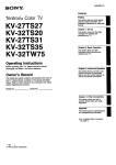
Trinitron® Color TV
KV-27HSR10
KV-32HSR10
Operating Instructions
Before operating the unff, please read this manual thoroughly
and retain it for future reference.
Owner's Record
The model and
the unit. Record
below. Refer to
dealer regarding
Model No.}"_
....
sei'ial numbers are located at the rear and
these numbers in the spaces provided
them whenever you call upon your Sony
this product.
_.
- °
@1990 by Sony Corporation
_
Serial No.
To prevent fire or shock hazard, do not
expose the unit to rain or moisture.
_ISK OF
ELECTQiC
DO NOT
CAUTION
TO
OO
NO
REFER
REDUCE
NOT
THE
REMOVE
TO
TO PREVENT ELECTRIC SHOCK, DO NOT USE THIS
POLARIZED AC PLUG WITH AN EXTENSION CORD,
RECEPTACLE OR OTHER OUTLET UNLESS THE
BLADES CAN BE FULLY INSERTED TO PREVENT
BLADE EXPOSURE.
SHOCK
OPEN
RISK
COVER
USER.SERVICEABLE
SERVICING
OUALtFIED
OF
ELECTRIC
(OR
SHOCK.
_ACK)
PARTS
SERVICE
INSIDE
PERSONNEL
This symbol is intended to alert the user
to the presence of uninsulated
"dangerous voltage" within the product's
enclosure that may be of sufficient
magnitude to constitute a risk of electric
shock to persons.
This symbol is intended to alert the user
to the presence of important operating
and maintenance (servicing) instructions
in the literature accompanying the
appliance,
2
ECAUTION: ]
Note 'to CATV system installer in the U.S.A.
This reminder is provided to call the CATV system
installer's atteniton to Article 820-22 of the NEC that
provides guidelines for proper grounding and, in
particular, specifies that the cable ground shall be
connected to the grounding system of the building, as
close to the point of cable entry as practical.
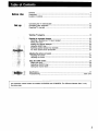
Before Use
Setup
v
Features .....................................................................................................................................
Precautions ................................................................................................................................
Location of controls ..................................................................................................................
4
5
6
Connecting the TV antenna/cable ............................................................................................
Connecting other equipment .....................................................................................................
Presetting TV channels .............................................................................................................
10
12
16
Watching TV programs ..............................................................................................................
18
Enjoying the convenient features ..............................................................................................
Receiving a Multichannel "IV Sound program ......................................................................
Muting the sound ..................................................................................................................
Keeping the channel displayed .............................................................................................
Using the SLEEP timer ..........................................................................................................
Switching quickly between two channels ............................................................................
For more natural sound reproduction ...................................................................................
20
20
20
20
20
20
20
Adjusting the picture and sound ..............................................................................................
Adjusting the picture .............................................................................................................
Adjusting the sound ..............................................................................................................
21
22
24
Using the
Setting
Setting
Setting
25
26
28
30
GUIDE fention ...........................................................................................................
the clock ....................................................................................................................
the ONIOFF timer .....................................................................................................
the channel block .....................................................................................................
Specifications .............................................................................................................................
31
Troubleshooting ...........................................................................................................
back cover
This instruction manual covers two models: KV-27HSR10 and KV-32HSR10. The difference
the picture size.
between them is only
3
This color TV features a Microblack TM
TRINITRON ® picture tube for a high
resolution, high contrast picture.
• Sound Retrieval System (SRS_)* enhances the natural sound of
any stereo source.
• Multi.band VHF/UHFICATV tuner receives up to 125 cable
channel for a total of 181 possible off-air and cable channels.
• Built-in MTS (Multichannel TV Sound) decoder enables reception
of stereo programs and Second Audio Program (SAP) broadcasts.
• S VIDEO IN jack which is connected to the S video output jack
on the VCR allows superior playback pictures,
• Variable audio output jacks enable reproduction of "IV or video
sound through an audio system.
• Monitor output jacks allow VTR recording of the picture and
sound being monitored on the IV.
* Sound Retrieval system (SRS) reproduces
the ambience
and dynamic
of
the original live performance
so that you can enjoy the sound as if you
were at the concert hall or in the recording studio. SRS enables you to
enjoy the optimum
sound from anywhere
(e) SOUND R_IEVAL
in the room.
SYSTEM
The (0) Sound Retrieval System is manufactured by Sony
Corporation under license from the Hughes Aircraft Company, a
subsidiary of GM Hughes Electronics. It is covered by U.B. Patent
No. 4, 748, 669. Other U.S. and foreign patents pending.
(0), Sound Retrieval System and SRS® are trademarks of the
Hughes Aircraft Company, a subsidiary of GM Hughes
Electronics.
4
Supplied Remote Commander
provides you many other convenient
features.
• Commanderallows you to operate the IV, a Sony VCR and a
multi disc player from a distance.
• Guide function allows,you to set the clock, timer, channel block,
while readingthe instructionsof the on-scrsenguide.
• Automatic programmingto preset all receivablechannels
instantly.
• JUMP button enables switchingquickly between two channels.
• Sleep timer automaticallyturns off the TV after approximately
one hour.
• ANTIAUX button permits one-touchselectionof pay cable IV
channels when a converter is connected.
• Internalclock for the current time display
And other features for a high quality
picture...
• New Dynamic picture TM system adjusts picture contrast
automatically to produce more detail in both bright and dark
areas of every scene.
• New Dynamic Color TM system assures accurate, life-like skin
tones and pure whites.
• coiorpure Filter TM produces fine picture detail without color spill
or color noise.
• VM (VELOCITY MODULATION) circuitry produces clean and sharp
black and white contrasts. (Only for KV-32HSR10)
• Dynamic Focus TM circuitry automatically focuses the scanning
electron beam for enhanced sharpness over the entire picture,
especially in the corners. (Only for KV-32HSR10)
• Trinitone TM control arlows you to adjust the color temperature
(tint) of the picture for the most pleasing color.
Safety
• Operate the unit only on 120 AC.
• One blade of the plug is wider than the other for purpose of
safety and will fit into the power outlet only one way. If you are
unable to insert the plug fully into the outlet, contact your
dealer.
• Should any liquid or solid object fall into the cabinet, unplug the
unit and have it checked by qualified personnel before operating
it any further.
• Unplug the unit from the wall outlet if it is not going to be used
for several days or more. To disconnect the cord, pull it out by
the plug. Never pull the cord itself.
Installation
• To prevent internal heat build-up, do not block the ventilation
openings.
• Do not install the unit in a hot or humid place or in a place
subject to excessive dust or mechanical vibration.
Cleaning
Clean the unit with a slightly damp soft cloth. Use a mild
household detergent. Never use strong solvents such as thinner or
benzine as they might damage the finish of the cabinet.
Repacking
Retain the original carton and packing materials for safe transport
of this unit in the future.
Use of this television receiver for other than private
viewing of programs broadcast on UHF or VHF or
transmitted by cable companies for the use of the
general public may require authorization from the
broadcaster/cable
company and/or program owner.
If you have any questions or problems concerning
unit, please contact your nearest Sony dealer.
For details safety precautions,
"IMPORTANT SAFEGUARDS".
your
see the leaflet
5
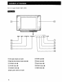
Refer to the pages indicated
in •
for details.
I
I
[]
[]
[] TT
[]
[]
[]
[]
[]
[]
[]
[]
[]
Left speaker (tweeter and woofer)
[]
POWER switch
[]
(•)
[]
Remote sensor
[]
TVNIDEO
[]
SLEEP indicator •
[]
VOLUME buttons •
[]
STEREO indicator •
[]
CHANNEL buttons
[_ TIMER indicator
[]
Right speaker (tweeter and woofer)
6
SRS (Sound Retrieval System) button •
button
[]
[]
[]
@ @
® @
IDE0 T _
@
[]
S VI_EO
_o3
Q
T
VII_ 0
@
Q
_ll@ll
VtlF/UtlF
[]
[]
[]
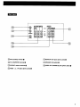
[] AUX (auxiliary)terminal •
[]
MONITOR OUT jacks (phone jacks) •
[] TO CONVERTER'terminal•
[]
SPEAKER SW (switch)
[] VHFlUHF antenna terminal •
[]
AUDIO OUT (VARIABLE) jacks (phono jacks)
[] VIDEO 1, 2, 3 IN jacks (p/normjacks)
7
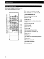
Refer to the pages indicated in • for details.
The buttons with ,_ mark have the same function as the
buttons with the same or similar mark on the TV.
r_V'rR
I/2/3/MDP
[]Sony
VCRImulti disc player operation buttons @
r_channel
_Z3
--
presetting buttons _
[_ANTIAUX
[]
(multi disc player) selector •
(antennalauxiliary) button
[]
MUTING button
[]
CABLE button
[_lnput
select buttons (TV, VIDEO 1, VIDEO 2, VIDEO
3)* •
[]Channel
%--
number buttons
[]DISPLAY
_]ENTER
[]
[_]TIME
[]S
T
[]
[]
[]
[]
button _
button
MTS (multichannel TV sound) button
[_SRS
[]
button
(sound retrieval system) button*
SLEEP button
[_] POWER button'_
[_A/V
WINDOW (audio and video adjusting) buttons
_]JUMP
bL
J
[_]CH
r_VOL
button •
(channel) scan buttons*
(volume) control buttons*
[]PICTURE
8
buttons
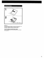
1
2
(R6) batteries
x2
Battery life
In normal operation, batteries will last up to half a year. If the
unti does not operate properly, the batteries might be
exhausted. Replace both batteries with new ones.
To avoid damage from possible battery leakage
Remove the batteries when the commander will not be used
for a long time.
9
Cable TV reception is only possible by connecting
cable supplied by your local cable operator.
Either an indoor antenna or outdoor antenna can be
connected. For better quality picture, connecting an
outdoor antenna is recommended.
iin
a
I
m
•
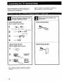
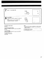
Check the cable type and prepare the cable
end using the appropriate connector.
p,_
lug of
thethe
connector
into VHFIUHF
rear
TV.
] 75-ohm coaxial cable (round) I
75-ohmcoaxial cable (round)I
Attach an optional F-typeconnector.
1
7 mm (1/4inch) 10 mm
(3/8
inch)
F-type connector
VHF/UHF
2
3 mm (1/8inch)
3
4
300-ohm twin-lead cable (flat) ]
I 300-ohm twin.leadcable (flat) r
Attach the suppliedantenna connector.
VHF/UHF
screwdriver.
_
3
* Most combination
antennas
splitter, Remove the splitter
connector,
10
Loosen with a
Attach the
cable and
fasten with a
screwdriver.
are equipped with a signal
and attach the appropriate
on the
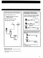
When you connect both VHF and UHF antennas
When you connect a cable with a special
converterldecoder*
for pay cable TV systems
Use the optional
Pay cable "IV systems use scrambled or encoded
signals and require special converters (decoders) in
addition to the normal cable connection.
1
EAC-66 U/V mixer.
the VHF antenna end using the
appropriate connector.
: Signal flow
Connect the cables to the mixer.
3
Plug the mixer to VHFIUHF.
AU×
Converter/
UHF
VHF
CONVERTER
VHFIUHF
coaxial cable
CATV
cable
When you connect both VHFIUHF antennasand a
CATV cable
_'_}"
AUX
CATV
cable
TO
CONVERTER
VHFIUHF
VHFIUHF
antenna cable
Note
In this case, do not connect anything to the TO
CONVERTER terminal.
When the UIV mixer is used
Snow and noise may appear in the pictures
channels over 37 (W + 1).
* The special converterldecoder
system operator,
of the cable TV
will be supplied by the cable
11
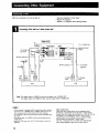
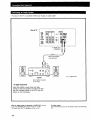
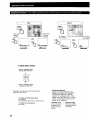
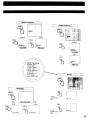
With this connection,
you will be able to...
--View the playback of video tapes
--Record "IV programs
--Record a TV program while viewing another
Connecting VCRs with an S video output jack
I Rear of TV]
to
VIDEO IN
._:::_J:
/
l
YC'15VI30V-"l
Signal flow
o MONITOR
OUT
__ll,_
S VIDEO
RK-T4A (optional)--_-_../I
tovHFl_-'w
--
_uM ONIDTOi
L---
_
outpul
output _r_
_[
YC-15V/30V
(optional)
[_
VCR
VCR
Note: The signal input to VIDEO IN cannot be output from S VIDEO OUT.
The signal input to S VIDEO IN can only be output from S VIDEO OUT.
• If you connect a monaural VCR, connect the audio output of
the VCR to the L (MONO) jack of VIDEO 1/2/3 IN of the TV.
The monaural sound will be heard from both speakers.
• For operation, refer to the instruction
manual furnished with
the VCR.
• The signal input to S VIDEO IN can only be output from S
VIDEO OUT.
• Keep the VCR away from the TV if the picture or sound is
affected.
12
About S video input
Video input and output signals can be separated into Y
(luminance or brightness) and C (chroma or color) signals,
Usually these two signals are combined in a VCR and sent as
one signal to a TV. Separation of the Y and G signals
prevents them from interfering with one another, thereby
improving picture (especially in color) quality.
This unit is equipped with an S video input jack through
which these separated signal can be input directly.
P4
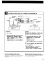
Connecting VCRslvideo disc players, etc. not equipped with an S video output jack
VMC-810S/820S
_:
/
Signal flow
(oP tional )
to MONITOR
OUT
(optional)
audio
L
• ' outDuI
VHF/UHF
to audio
to video
output
input
input
VCR, Video disc
player, etc.
VCR
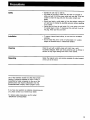
Preparations]
1
t,j
_,,
I
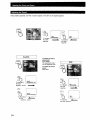
Operation ]
Wllen using a Sony infrared remote control VCR, video
disc player or multi disc player, the equipment can be
operated with the supplied Remote Commander.
Tum on the TV.
Press the TVNIDEO button on the TV or an input
select button on the commander so that the
"VIDEO 1", "VIDEO 2" or "VIDEO 3" indication
appears on the screen.
VIDEO 1: for equipment connected to VIDEO 1 IN
VIDEO 2: for equipment connected to VIDEO 2 IN
VIDEO 3: for equipment connected to VIDEO 3 IN
1
Set the VTR1-2-3-MDP selector to the desired
position according to the equipment to be
operated.
VTR 1: Sony Betamax VCR
V'I'R 2: Sony 8 mm VCR
V'I'R 3: Sony VHS VCR
MDP: Sony Video disc player or multi disc player
2
Press the VCRImulti disc player operation button
on the commander.
To return to the TV mode
--Press the TV/VIDEO button on the "IV so that a
channel number appears on the screen.
--Press the "IV button on the Remote Commander.
To view one TV program while recording another
Press the TV/VTR mode select button on the VCR or
commander so that the VCR will be in the TV mode. Press the
TV button on the commander,
want to view.
and select the channel
you
When you cannot obtain a clear picture andlor sound
Make sure that the TV/VTR mode select button on the VCR is
set to TV. Re-select the desired channel with the buttons on
the TV or the Remote Commander.
13
--To
listen to the "IV or connected
VCR sound through an audio system
Rear of TV
@ @
svl_
@ ®®o
r_
O @ I@_3
,q
"_lFl@lf
to AUDIO OUT
(VARIABLE)
RK-74A connecting
cord (optional)
tl° e
iop°____
[-_
I,-X-{I
.,_
: Signal flow
Amplifier
Set Amplifer's
function
to line input.
To adjust sound level
Leave the amplifier volume, bass and treble
controls at their mid position and adjust the level
with the VOLUME buttons on the TV or the VOL
buttons on the Commander.
When an audio system is connected to AUDIO OUT, be sure
to set the SPEAKER SW (switch) on the TV to OFF,
The sound from the TV's speakers will be cut off.
14
For better sound
We recommend that you use the optional
31).
video rack (see page
15
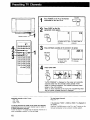
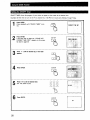
1
POWER
Press POWER on the TV or the Remote
Commander to turn the TV on.
appropriate
appears.
Press CABLEmode
so that
the
l
CABLE
%
Remote sensor
c31
To preset VHF or UHF
channels
Press ANTIAUX
according
to
the
channel
To preset
channels
he
to
cable TV
preset.
-1
ANT/AUX
3
_-_
To preset pay cable
To preset VHF,
or regular cable
13/channels
r- oE3-
4
31
Press AUTO
UHF
TV channels
PGM.
AUTO
PGM
"AUTO PROGRAM" is displayed on the screen and receivable
channels (other than the channels already preset) will be
preset in numerical sequence. The channels previously preset
remain in the unit's memory.
When no more channels can be found, the programming stops
and the lowest numbered channel is displayed.
Receivable channels of this TV are:
VHF: 2-13
UHF: 14-69
Cable: 1-125
To add the channels that could not be preset with automatic
programming because their signal strength was too weak, or
to erase unnecessary channels.
Follow the steps in "To preset only the desired channels or to
erase unnecessary channels"
on the next page.
16
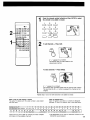
To check preset channels
Press CH +1-.
If the indication "VIDEO 1, VIDEO 2, VIDEO 3" is displayed on
the screen
Press the TV/VIDEO
button on the TV. or the TV button on the
Remote
so that a channel
Commander
number
appears.
1
Press the channel number button(s) and then ENTER to select
the channel to be added or erased.
1
2
3
4
5
6
7
8
9
_
r--1
2
_r--_
m
Qr--_
To add channels -- Press ADD.
ADD
A "+" appears for a moment.
This channel has now been added to the
channel
scan memory.
To erase channels-- Press ERASE
ERASE
A "-"
appears for a moment.
This channel has now been erased from the channel scan memory.
The next time the CH +/- button is pressed, this channel will be
skipped.
Repeat steps 1 and 2 for other channels
When a VHF or UHF channel is erased
The cable TV channel with the same number
and vice versa,
Number on this TV
_Vchannel
31
R
Check
32
S
33
T
34
U
1
5
A-8 A-7
35
V
6
A-6
15
e
16
c
17
D
18
E
19
F
20
G
21
H
22
I
23
J
24
K
25
L
26
M
27
N
28
O
29
P
30
Q
36 37 38 39 .................. 93 94 95 g6 97 98 99 100 101 102 .................. 123 124 125
W w+r W+2W+3 .................. W+57w+58 A 5 A-4 A-3 A-2 A-1 W+59W+60W+61..................
W+82W+83W+84
with your local cable TV company
information
Cable TV channel chart*
Cable TV systems use letters or numbers to designate
channels. To tune in a channel, refer to the chart below.
is also erased
14
A
to be added or erased.
on the available
channels.
for more complete
*The designation
EIA/NCTA
of the cable TV channels
recommendation.
conforms
I
!
to the
17
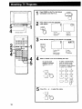
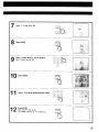
1
2
Press POWER on the TV or the Remote
Commander to turn the TV on.
POWER
Press CABLE so that the appropriate
031
CABLE
%
mode
4'
Remotesen_o_---'J
3
appeam.
I
To view
VHForUHF
channels
Press ANTIAUX
according
To view
cable TV
channels
to the channel
ANT/AUX
4
to be watched.
31
AUX 31
To view VHF,
To view
UHF or
regular cable
TV channels
pay cable
TV channels
Select a channel in one of the following two ways:
To scan the preset
channels In numerical
sequence, press CH
+/-.
To select a channel directly,
press the channel number
button(s) and then ENTER.
For example, to select channel
10, press 1,0 and ENTER.
1
F-n
2
_-1
4
5
7
8
v--1
V--7
0
Press VOL
18
+ or -
to adjust
the volume.
3
r--1
6
9
F-]
ENTER
Notes
To turn off the unit
Press POWER on the TV or the Remote
Commaner
again.
If the indication "VIDEO 1, VIDEO 2, VIDEO 3" is displayed on
the screen
Press the TV/VIDEO button on the TV or the TV button on the
Remote
Commander
so that a channel
number
appears.
19
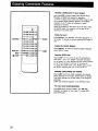
ReceMng a Multichannel 'IV Sound program
Each time MTS is presed, MAIN, SAP (Second Audio
Program), or MONO are seleoted in sequence.
To listen to stereo sound, select the MAIN mode so that
the on-screen MAIN indication appeam. The STEREO
indicator on the TV lights up whenever a stereo
broadcast is received.
When the reception of the stereo sound is noisy, select
the MONO mode. The reception will be easy at the
sacrifice of the stereo effect.
Muting the sound
MUTING --
SLEEP
Press MUTING. The "MUTING" indicationwill appearon
the screen.To restore the sound,press MUTING again or
VOL +.
Keeping
thechenn d ptayed
DISPLA¥--
_JUMP
Press DISPLAY. To make the channel display disappear,
press DISPLAY again.
MTS-(e)
SRS--
Using the SLEEP timer
Press SLEEP. The TV will be turned off automatically
after about 1 hour. The "SLEEP" indication will appear
on tile screen for a few seconds and the SLEEP indicator
on the "IV will remain lit until the TV is turned off.
To cancel the SLEEP timer, press SLEEP again so that
the SLEEP indicator goes out, or turn off the TV.
_Ing
quickly _
two channels
Press JUMP. Each time JUMP is pressed, the channel
which appeared on the screen directly before is recalled.
This button enables you to keep track of two programs
alternately.
JUMP also switches programs in the ANT/AUX mode.
For more natural Sound :_lon
Press SRS (sound retrieval system). The "(Q) SRS"
indication will appear on the screen. To cancel SRS,
press SRS again.
20
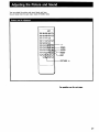
You can adjust the picture and sound levels and have
the unit store them for each input mode ('FV/VIDEO 1/2/3).
--.-------
r_
+1VIDEO
AUDIO
;;!-O-n
PICTURE +1-
Rx ope_tio_ seethe r_xt pages.
21
I
HUE
COLOR
VIDEO
VIDEO
%
Skin
Skin tones
become
become
purplish.
greenish.
To increase
ro decrease
color intensity
h_
_l|lillffLlilrHIIHIIl|P_lP]
t Illlllll_lllflll
%
I_lmHl_
• IlHllHrnl_lmlll_lUm
_
Ic_-_m%M,_,m_,m,,m_
............
To adjust picture contrast
Press to increase picture
contrast with vivid color
[_+
PICTURE
Press to decrease picture
contrast with soft color
The
under
picture
Contrast
each
input
bevel cannot
be memorized
mode.
To restore the factory preset levels
Press RESET.
The adjustment levels will be cleared at once.
To restore the normal picture
Press EXST.
22
]
* TRINITONE adjustment
Usually color picture tubes are manufactured with a fixed color temperature
(tint) that determines the "warmnes
(reddish)" or "coolness (bluish)" of the
picture it produces. With Sony*s Trinitone
feature, you can adjust the color of the
picture to your preference.
TRINITONE LOW
•---.
A touch of red will
be added to the
white part of the
picture.
TRINITONE HIGH
The factory preset
whiteness level will
be restored.
color intensb
COLOR
dff_lml.................................
I
BRIGHT
(brightness)
I
SHARP (sharpness)
VIDEO
VIDEO
_}
BRIGHT
Darker
Brighter
Sharper
_
I,%";_%,,,,,,,,,,,,
..................
BRIGHTNESS
IlillBIl| I...............................
SHARPNESS
IINIIHIIIHIII_IIHII|
HIIIIm
HIIIIIIH
...................
Softer
r_n
_IIHIIHIIIIIIIF
...........................
SHARPNESS
If dots or stripes
appear while
you are watching
picture from
vaidCe(omsPoU_
recr
eOra
a
I
/
NOTCH
i
VIDEO
%
TRINITONE*
-]
VIDEO
To set
NOTCH
ON.
For
TRINITONE HIGH
bright
white
TRINITONE
HIGH
TR[NI TONE
NmCHON
For
soft
[Z£3
white
L_
filter
LOH
I
To set
NOTCH
OFF.
_
filt er
NOTCH OFF
",,..._
23
Press AUDIO repeatedly
until the on-scr_n
display of the item to be adjusted appears.
AUDIO
TREBLE
lll_JllHlllil_
.......................................
To increase
the
To decrease
the treble
t rebie
response
response
BALANCE
To restore the factory
preset levels
Press RESET.
The adjustment
levels
will be cleared at once.
AUDIO
To restore the normal
picture
Press EXIT.
_
I
BASS
AUDIO
%
BALAk_E
To emphasize
the right
speaker's volume
IHIIInUHIIUII_II,
lllNllm
To increase
ii_lll_l%,_lm,m ................
the bass
response
BALANCE
IINI
_=_ll_l_llmll_ll_ll_llNl_l_l
To emphasize
the left
speaker's
_
volume
BASSHIIh
To decrease
the bass response
24
(
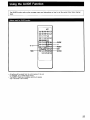
The GUIDE function
block.
calls up the on-screen menu and instructions
on how to set the current time, timer, channel
JIDE
• All setting will be erased from the unit's memory if the unit
is unplugged, or if a power failure occurs.
• The ON/OFF TIMER and CHANNEL BLOCK will operate
only if the clock is set correctly.
25
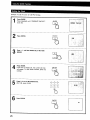
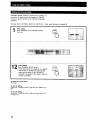
Example: To set the clock to 5:30 PM, Monday.
GUIDE
Press
until "CURRENT TIME SET"
Press repeatedly
GUIDE.
turns red.
2
Press ENTER.
3
Press +/- until the desired day of the week
appears.
%
ENTER
ENTER
If
the time
is already set, the current set time
Press
ENTER.
will appear. To clear these numbers, press any
number.
5
Press0-9 to set the desired time.
(For 5:30, press 0,5,3,0)
%
4
5
6
7
8
9
0
?5
6
26
Press ENTER.
ENTER
%
AM
7
Press +1- to set AM or PM.
PM
PM
The
Pressmoment
ENTER. ENTER is pressed, the clock will
start.
Now, the clock is set. The indication will
disappear after approx. 5 seconds.
To restore the normal picture
Press EXIT.
To clear the current time setting
Display the "CURRENT TIME SET" page and press RESET,
then EXIT.
ENTER
%
Notes
• The internal clock of this TV operates on a 12-hour cycle, I1
a 24-hour cycle number is entered, it will be cleared when
ENTER is pressed.
12:00 AM stands
for midnight.
12:00 PM stands
for noon.
To reset the setting
Display the "CURRENT TIME SET" page and press RESET,
then repeat steops 3 to 8.
To display the current time
Press TIME.
27
ON/OFF TIMER allows the program of your choice to appear on the screen at the desired time.
Example: Set the timer to turn on the TV to channel 8 at 1:00 PM for 3 hours every Monday through Friday.
i
Press
until "ON/OFF TIMER" turns
Press repeatedly
GUIDE.
red.
If
the clock
has not been set, "PLEASE SET
Press
ENTER.
CURRENT TIME FIRST" appears on the screen.
Go back to page 26.
3
Press +1- until the desiredday of the week
appears.
4
Press ENTER.
5
Press 0-9 to set the desired time.
(For 1:00, press 0,1,0,0.)
GUIDE
%
ENTER
I
¢'_ I
ENTER
%
&_
8
7
9
_E2J_
o
6
28
Press ENTER.
ENTER
%
AM
,
t#
7
Press +/-
8
Press ENTER.
9
Press a number button to set the duration.
(Up to 9 hours can be set).
to set AM or PM.
ENTER
%
7
0
10
Press ENTER.
11
Press 0-9
ENTER
%
1
2
3
7
8
9
to set the desired channel number.
•
2 .ress
Now ON/OFF
ENTER. timer is set.
The TIMER indicator on the TV lights up.
_
i_
¸
ENTER
%
29
CHANNEL BLOCK prevents a channel from appearing on
the screen for preset hours. We suggest you use this
function to prevent children from watching undersirable
programs.
Example: Set the CHANNEL
BLOCK at 4:00 PM (for 1 hour), every Saturday, at channel 12.
Press repeatedly
Press
GUIDE
until "CHANNEL
turns red.
BLOCK"
Now
BLOCK is set.
PressCHANNEL
ENTER.
At the preset time, the picture of the selected
channel will be blocked from view and the
sound will be muted. A red "BLOCKED"
indication will appear on the screen while the
channel is blocked.
To restore the normal picture
Press EXIT.
To clear the setting
Display the "CHANNEL
EXIT.
BLOCK"
page and press RESET, then
To reset the setting
Display the "CHANNEL
the beginning.
BLOCK"
page and repeat
30
steps from
GUIDE
ENTER
Television system
American TV standards
Power requirements
120V AC, 60Hz
Channel coverage
VHF: 2-13
UHF: 14-69
Cable TV: 1-125
Power consumption
KV-27HSR10
225W (max.)
1.5W (in standby condition)
Picture tube
Microblack
Trinitron
tube
27-inch picture measured diagonally
28-inch picture tube measured
diagonally
(KV-27HSR10)
KV-32HSR10
240W (max.)
1.5W (in standby condition)
Accessories supplied
Remote Commander RM-763
with 2 size AA EVEREADY
batteries.
Antenna connector (1)
32-inch picture measured diagonally
34-inch picture tube measured
diagonally
(KV-32HSR10)
Optional accessories
Antenna
75oohm external antenna terminal
for VHF/UHF
Input
VIDEO 1, 2 and 3 IN
S VIDEO IN (4-pin mini DIN)
Y: 1 Vp-p, 75-ohms
unbalanced, sync negative
C: 0.286 Vpop (Burst signal),
75-ohms
Video (phono jacks): 1 Vp-p,
75-ohms unbalanced, sync
negative
Audio (phono jacks): 500 mVrms
(100% modulation)
Impedance: 47 kilohms
Output
UIV mixer EAC-66
Connecting cable
VMC-810/820S
YC-15V/30V
Video rack
SU-235X (with super-woofer)
SU-235X (with super-woofer)
SU-251 (black)
SU-330 (black)
Design and specifications
notice.
are subject to change without
MONITOR OUTPUT
S VIDEO OUTPUT (4-pin mini
DIN)
Y: 1 Vp-p, 75-ohms
unbalanced, sync negatiw
C: 0.286 Vp-p (Burst signal)
75-ohms
Video (phono jacks): 1 Vp-p,
75-ohms unbalanced, sync
negative
Audio (phono jacks): 500 mVrms
(100% modulation)
Impedance: 10 kilohms
AUDIO OUTPUT (VARIABLE) (phono
jacks)
More than 408 mVrms at the
maximum volume setting
(variable)
Impedance: 5 kilohms
31
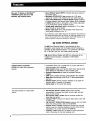
Disturbances in picture and sound can often be eliminated
by checking the symptoms and following the suggestions
listed below.
SYMPTOM
CHECK AND ADJUST
• Adjust PICTURE.
• Adjust BRIGHT.
• Check antenna/cable
connections.
Poo_ or no picture
(Screen not lit),
good sound
•
Press VOLUME + on the
TV or VOL + on the
Remote Commander.
Press MUTING on the
Remote Commander.
•
Good picture,
no sound
•
Check that the MTS button
is set correctly.
• Check that the TV/VIDEO
button is set correctly.
• Set the SPEAKER SW
(switch)
•
•
Plug the unit into a wall
outlet.
• Check that the TV/VIDEO
No picture (screen
not lit), no sound
button
No color
Is it a color program?
Adjust COLOR.
•
Is it an active or the
correct channel?
Check the CABLE
•
setting.
Check the ANT/AUX
button setting.
Check antenna/cable
connections.
•
only
•
_
.,._-:2
. _. € .
!m-_*_":_i'7'
_"'I
,
_
_
_
i _'_ [ _"_"_UJ
or
t ,, _'_,4_--
stripes
_
I _
This is often caused by local
interference. (e.g. cars, neon
signs, hairdryers etc.) Adjust
antenna for minimum interference.
Dotted
lines
Double
'_
is set correctly.
•
•
Snow and noise
r
to ON.
Is POWER switched on?
ghosts
orimages
Reflections from nearby
mountains or buildings often
cause this problem.
A highly directional outdoor
antenna or a CATV cable
may improve
Try another channel. It could
If the problem
Sony
Corporation
be station
persists, contact
Printed
in U.S.A
the picture.
trouble.
your nearest service facility.