1
SONYe
STEREO VIDEO CASS€lTE RECORDER
-:
-4
.
A
A
&*
+ *wg'
i.
OPERATIPI-=
TABLE OF CONTENTS
-
. . , -
Before omretin0 the m;-'pleWe
m d thi manuel
OWNERS RECORD,
Tlw m W and 8erlal nunbera of ywr set are l m t d
ath-Recdtbes&dnumWinthespem
b l o w . Refar to h a 8 n u m b whmew yw
call u p n your Bony Wer regevding this product.
M-1
No. SL-t#5M3
Serial No.
Presetting the t M v e chnerls in your
area-m.......m.mm..
30
......................................................3-i
Tkble
c h b ........... :...........,.
..............back ewer
Swifications
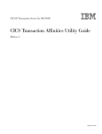
super Betahl-ffi
--
This unlt oan be lrsed with m video cassette
It Is campatbfa with tb IBB and
type recording
;and playback formats, and will play beck
in msr imu
Fta1
To prevent flre or shock hazard, do not expose the unit to rain ot moisture.
I
CAWON : TO REOW€ THE RlSK OF ELECTRIC SHOCK,
DO NOT REMOVE C W E R (OR BACK).
NO USERSERVICEABLEPARTS I HSIDE.
FEFER SERVICING TO DUAUFIED SERVICE PE-NEL
I
Thls symbol lo Intended to alert the
user to the pretience of unlnsulrted
"dangerous voltage" within t ha p r d uct's enclosure that may b of euffi.
clent magnitude to constitute a rlsk of
electric shock to petsms.
This symbol Is intended to alert the
user to the gresenee of important
operating and
rnalntenance (sewking)
instructions in the literature accompanying the appliance.
CAUTION :
TO PREVENT ELECTRIC StlOCK, DO NOT USE THIS
POLARIZED AC PLUG WITH AN EXTEN$ION CORD, RECEPTACLE OR OTHER OUTLET UNLESS THE BLADES
CAN BE FULLY INSERTED TO PREVENT BLADE
EXPOSURE.
WORMArnN
This equipment
M k m s radio
w a n d If n o t i ~ l e d m d w e d ~that
y ,
Is, In &kt eccdawe wtth the mmufacturer's
imhxtbm may c a m htaWmce to radlo end
blavblon meptbn. R hm been Zype tested and
Poondto~withtheIlmbtsaC&aB
oomputlw devioe In accordance wtth the
specificatiwvs in 8rrbpert J of Part 16 of FCC Rules,
which &re d e s i i b provlda -le
proteetian
against smh intwkmnce In a midentid
Irwtalleth. W ~ v d rtbm
,
is no
that
inWfmme wlll not cccw In a pertlcular Installation.
If this equipment
cawre interference to radio w
televiiim m,
w h i i can tm btmmined by
turn in^ the equipmgnt off and an, the mw Is
mcouraged to by to correct the interference by one
or more of the following measurm :
- reorient the receiving mtenna
- rebate this equipment with respect to the
receiwr
- move this equipm~ntaway fnxn the reoeiwr
- plug this equipment Into a different outlet so that
equipment and r
d are on different h n c h
circuits.
H ,dm user should consult the deaIer or
an experknced redio/tehision technician for
M t l o n a l wqgwdims. fhe usm may find the
-
following boaWet prepared by the Federal
Communicatlans Commission helpful :
"How to Identify and Resolve RadbTV I n M w m c a
W e m s " . This booklet $ ewdkibk fram the US.
-mnt
Printing M i ,Wdlngton DC, 20042
stock
No.
-
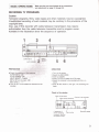
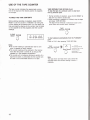
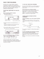
WHAT B E T A HI-FI RECOCIDH03
Before operating, cheek thaR the operating pmw
In conventional recording, w i i o signels EUB recorded on
v ~ a r r d f f q u m o y d t h a t m i t ~ ~ w l t h
the audlo track and video signals on the video tmk. In
t h w of your local poww m.
Bete hl-fl recording, audio signals an, recwded an the
8hwld any solid o b f d ar
rtpao~e-nef
video treck together with wlth tbe v k m a i m d n g 2
unplug the unlt and heane t
by Qualtfkd
~~~.
personnel befwe opmting'ft any*.
l
b Beta hi-fi audio signals are fmquency-moduleded
md recorded on 2 channels, so that you can -r
a
muMchnm4 stereo
with sound quality tar
suwbr to that of the c o m t i o n a l audlo reeordlng.
Beta hi-fi recarding pattern on the video tape
i b M
cSw
Ion hntmthml
mAllow~aIrclrculationtopnrventkrtemetlheett
txllldup.
*Do not plt
b unlt an swfaoes h,
ManW,
etc.) or neEir mmbials (cvtains, -1
Umt mw
blaek the venbllatian slob.
.DonotImtallftreunitnearhmt8umessuchas
radlmm or dr ducb or in a p k e sllbject to direct
sunlight, excmlve dust, mechanical vibration or
shock.
.The unit Is designed for
In a Mzantal
position. Do not Install it in an Inclined position.
mKeep~unitand~bpeeawayfrwn
equipment with strong magnets, as for example a
mic~mraveoven or a -I
. -I
cbm m the unlt
.Do not plwe any
-
.
I
,
,
.;
-
. , I , i'?..
'
<I&;
.When theunit Is mt In,
~ ~ a a r l B
*Remweandstue~
video end W e hi-fl audfo
-
Wh
Audklemw
m
For rscading/&tesk
u.---
When lha W A HI-FI switch is sat to ON, this
~recordswdlosiglelsonthevidmtrmk(geta
or
hl-fl mordhg) md on the oanventid audio track at
plam.
.. .
thesetmettme,~thattheaetawcanahbeplayed
m 8 t o r s t f m ~ I n t h e i ~ ~ ~ ' l ) r e m k r
beck on any ordinary vkleo c a m recorder wtthwt a
muprtghtposttit[ontopr;evlentintnrsb?lofdustand
Beta hi-fi system.
uneven wlndhg.
e
..,t-
FsiiGl
Clem the cabjnet. panel and cmWb with a ssft dry
cloth, w a soft cloth lightly mdstened with a mild
dempnt solution.
Do not use m y type of sobent, such as abhol ar
benzine w h i i might dmwge the finish.
Do not throw &way the cwtm and packlng matmiah.
They meke an idsel mntainer in which ta t r m the
unit. When a
h
m
r fhs m l to mother tocsttlon, repack
it~Il~anthecerton.
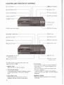
LOCATION AND FUNCTION OF CONTROLS
I
II 7
CLEAR/RESET button
"Inw
PEAK LEVEL METER
-STEREO
-SAP
Indicator
indicator
1
POWER switch and indicatw
I
TIMER SET button
HEADPHONES
L
-rape trmspMt
-
m Buttons for various
playback modes
use of m h control, refer to the
pagw indicated in the
rnlWEcT
WcK TIMER button
and
PHONE txvEL control
For details on tha
TIMER REG button
P w this button to eject the cassette.
TAPE Re7URN bu#on
In stop mode, presa thls button to advance or M n d
the tape approximately to the aounter -"
point.
m w / m button
Press this button to w e t the time counter to
D
w and dso to eteerr the tlmer setting.
[S]TV/m
button
Press this button to watch ttm proOram sdmtd on
the morckr. The 'W i n d i d o n ~ ~ I X U Nin
S the
diplay window.
(The 'VTW indication appeats automatically when
the button is pressed.)
To watch a different TV -ram
while recording
another, press this button wain. The 'VlR" indication
d
i
i
.
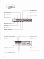
m.Rm8ENSOR
Detects tlw siganls transrnm fKwn the Remote
Commander.
CalPEAK LEVEL METER
This meter shows the peak input level of t
b right
and left channel8 during Eleta hi-fi recording.
mBWA H I 4 Indkabr
Light8 duing recording with the BETA Hldl switch at
tape,
ON. When playing baek a Beta hl-fi
Uw indicator lights up regardlw of the position of
the BETA HI-FI switch.
CLOCKS SET^
Press to start the set tin^ of the current time.
r*r " '
1
Q Lt@@d+W@
8
0
@
0
@
(b
6
0
@
0
@
@
@
@
GI
8
8
plw, mreturn play or
cm8etart em
NI pl-k
Ugtft$ during wording
m
m
d
e
Tlmer program p i t i o n during timer setting
Day i n d i e
Tum-on time of the t i m during timar setting
Lights durino fV chmml pmS@ttlrIg
Channel nurnbe!
Cable TV channel Indicator
Taple smed indlcatw
Lighb when TIMER REC ON/OFF or QUICK
TIMER is premed.
Clock display
During timer setting, the t u r n 4 time is
displayed.
T u r n 4 indicatw
Turnon indiwtx
Lights when a cmmtte k lnskia
Tapewunbr
Speedmddbecfionindimbrofttwtape
rlmwmmt * w ,-,A,
m,
- m c r . . - - - .-.
rr-
:>
.-.
.
*-.:*I&,*: I
[TIT-
cornpar-
-
I
OCHECK button
b e s to check the contents of the timer pmiettings.
mnmERsmbutaon
Press to sWt the M t n g or resetting of the timer
recording.
I3CHA-
krWons
Preas to select the ehennels and to set the clmk or
timer program.
(+/a)
M W T bttm
Press to tote to the next itan to be set dving
clock or timer setting.
@TIMER REC
Ress to eetivate the timer recording.
~ O U C Kn m mm
Prws this button to start the QUICK TIMER function.
REC LEYEL cwltrol
Adjust the recording 1selector is set to ON.
when the BETA HI-FI
@aRECbuth
Slide to the right to start the recording.
ljgBU#M#I for v a r b U E P l a Y b s d t ~ +
IIb FRAME, 1/10 SLOW, 1/5 SLOW
rnTmin9 trenspwt -m
rr REW (rewmd), b PLAY, W FF (fast mf
STOP. 11 / B!4 PAUSE/ST!U
Q AFT switch
Q ClEARbuttwl
Q CHANNEL 10 and I
d) TUHINQ button
@ ETbutton
STILL ADJ (adjust) button 9
~HEAZ)PHOWESJmckaw~LEVUeonlrol
Connect stereo headphones (with stereo PIWINB
jack)
to the HEADPHONES jack. The volume cstn be
controlled with the PHOME L E V U cantrol.
MPX FILTER selecrw
mSUP€RBETA W
H K I MONITOR nelmztor
h
1
*
VHF/UHF Qur m
m
LINE AUDK) IN Jwks( p h w typa)
LINE AUDIO OUT jda
type)
-
WNORMAL AUI)K)
Selelet the sound to be rea#ded on the ccm\rentlonal
audio w k . Normally set fo MAIN. To recud SAP
msumr--*
sound,s&toSAP.
PIPllMi h s e ~ - j f 7 ~ m b a b m d a p p e aInrthe
a
@Aura
sTER€o swstch
NormallysettoON.Whenthesignal iaweakma
peRlcular chennel, set to OFF.
~ r n ~ c d r d .
on the
Turn this knob to obtain the best poesibte plcture If
streak8 w anow appears W n g
msHARPNEm-l
A d j u s t ? 3 t h e ~ d t h e p i c t u ~ e i f ~ .
Normdly set the cantrot a? ttm canter d d m t position.
€alrarr.mEcr~ W p r o g r a m t o ~ ~ .
~ : f u ~ l n g T V p m O r a m s
UNE/PCM : Far m l n g s b d s fwnn the VIDEO/
E M IN and UNE AUDIO IN
LINE AUDIO : Fw recwding the swnd from UNE
AUDlOINmdttwpichmofTVprogramonFM
simulcast MiIq
@l
IIIPX FLTER sektw
MPX FILTER OFF: Normelly ast to this posibion.
MPX FILTER ON : For recordiw FM
PW-(But if your FM tuw han i n t m l MPX film set
to OFF.)
PCM : Far PCM recwdlng
~ l w ~ s d r o t o r
S e k t the channel Iw h e VCR program and the
output OUT from the VW/UHF eonmtor. Set dw
selectw to 3 CH a 4 CH,whlchew i not d v e in
your area.
mCQN7FPOLslnprRladr(mHtvpe~e
Connect to the CONTROL 8 output Wc of other
Sony pradwb for veriws systematic owudons.
H m A HI-FI a w M
ON : Normally #t to thii mitian.R-ing
will be
done in Beta hi-fi mtm.
OFF: Set to thh position to r e d only in the
conwmtional Spttern.
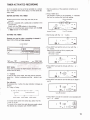
HANDLING THE VIDEO CASSETTES
~ U m a v a l l e b l e k r ~ m o d e
Belors-
The safety tab on the rear of the casawtb should not
be removed for recwdlng. When & new mwding is
m a d e a n a ~ ~ , t h e p r e v i w a
=ording will be eresed m l i b m t i ~ l y .
T o a v M e m b h a a ~
Break otl the safety tab wing a screwdriver or a similar
objwt, The cassette will be e w e d aulwnatically even
when you slide REC button to the right.
By selecting the recarding speed, MI[ or m,with the
REC MODE sefector, y w can decide the recording
time.
30 mln.
L-7w
L a
3 hr.
3 hr. 20 mln.
45 min.
1 hr. 30 min.
I
4 hr. 30 min.
6 hr.
The playback spwd is automatically set regardleshi oi
the REC M O M selectar's position.
To re-record on a c a d 8 whlch has Its d
tab m m w d
C o w ttw hole with a piece of plastic
y
w.
If you ecHvate REC, QUICK TIMER, or TIMER REG ON/
O R , when the- 1
cassette has ib safety tab
remwed,
lndlcator will appear in the indlcatlon
Imj
window and the cawmite will be w h n d c a l l y e-.
Insert the cemdte with the slde that hes the window
up (you c8n see the tap through the window).
Makeawethatyouhav%li~alltb~
BASlC OPERATIONS and
adjlwtments on page 23 through 30.
RECORDING TV PROGRAMS
Caution
Television programs, films, video tapes and other materials may be copyrighted.
U n M r s d recording of such material may be contrary to the provisions of the
copyrighi laws.
Also, use af this recorder with cable television transmission may require
auth&&bn from the cable television transmitter and/or program owner.
M u m h e m in the illsubation show the sequence of operation.
OPCRAImN
INPUT SELEeT+TLWIIER *
BETA HIR (on the reatj*
:
REG LEVEL-. * 5 "
~TmontheTVandselactthedmidfwthe
rercopder.
2 Select the FlEC MODE.
3 Inset3 a c e .
4 P r ~ NNlV
s
to d e c t the VTR
5 Select the G I ~ W to
I be r e c d d with
&.
m+~-
button.
6 Slide rn REC button to the right. The recording will
begin.
Cheek In the window
Lights durlw pauw.
Channel to be reowded
I
,navmma d & i i
and speed of tape.
To slop- r
When the
tape
STOP I.
ibs end, it wlll be rewound to
the beginning.
M&
T0M-m-b
Press PAUS€/STlLL (I/w. Ttm TV program can still
be seen on the TV, but the pictwe wlll not be mmd@.
To resume reowding, p ~ a s sP A E / S T I l L H/ bh again.
To protect the video heads and tlw tepe,the puse
modewlllbautomatiCally~aftwabout8
minutes and
wiN rtnp.
Noh
The p o w can be autMnatically twned on by insdng
a cass&e
w n g POWER OW/-.
w e AUTO STEREO is set to ON.
In the yem3 to come, an i m i n g number of
p-r
will be bro&msW in stmm. Called
Mutlichmnel TV Saund a MTS, the n
m technolo~y
will greatly enhance TV viewing by bringing you
programs with high fidelity stereo saund.
MTS also provides fw an extra channel called the
Second Audio Program or SAP which bm&asbm
cen use to mmit a second language for bilitransmissions w any other sound track.
To r e d a sdsroo brmckast
Set 8ETA H I 4 switch on the rear penel to ON. When
the STEREO indicatar lights up, a stereo broedcest is
M n g receivd. The r e d i n g procedure is the & a m es
USMI.
~bsckonanothsr~fromthev#y
beglnnkrOolths~runthetepeForaboutf5
seconds before stertlng W i n g . O t M w b you
may miss the starting point dulng playback an the
9.
OFF
BETA HI-FI
-NOTE
THE SUPER BETA WITCH
NornmtIy, keep his switch at the "ONmpositlm to
obtain high picturn quality d i m and playback
Tap6 recwded In other nokSVCRs can
b playd on -S
VCRs.
Tapes m h i d in Super&eba can be played on
other nonSupdeta VCRs :,-it
som
over-modulation noise may apIn the pictuFe
during playback.
If you intend to play back on ottw non4uperBeta
VCRs, then set the SUPER BFTA witoh to 'OFF"
witii when making y w r reoardlngs.
You can decide the M n g point for r e o o r d i ~while
watching the playbk picture or by see~chlnqfas t
b
point uslng the Betaicm and k t a Sklp&an (on page
12) functions.
me @nt where yw wish to sWt recording
on the tape by playing beek the tepe or using the
Betmxm w the Beta SkipScan function.
1 Search for
2 Prem I I / W PAUSE to stop the tape whwe you wish
to start recording.
3 Slide REC to ttm right. The m c d w will en* the
recording pawre mmle ml the pictun seby
INPUT SELECT wlll appaar on the monltor sawn.
4 Press II/H PAUSE to release t
b paw mode.
Recording stem.
To record a $AP
Audlo P r m m ) bodatst
Set NORMAL AUDIO to SAP. The SAP indicatw will
light up. If recording is & when there is a SAP
hodmat, the SAP sound will be r m d d an the
convantionel audio track while the MAlN sound is
recorded on the video tra& In 6eta hi-fi.
To listen tu the SAP sound, set AUDIO MONITOR to
NORMAL.
NORMAL AUDIO
To read a MAlN
only
MAIN. The MAlN sound will b
Set NORMAL AUDIO
recorded on the video track and the conventional audio
trwk.
Note
When a SAP sound is not to b recorded, be sum to
set NORMAL AUDIO to MAIN. If it la aet to SAP and
them is no SAP
no sound is re&
on
the conventional audio back.
mYw may find more noise in the reproduction of the
audio of SAP than In hat of the main awmd.
TO VMN OME TV PROGRAM WHILE RECORMJQ
ANOTHER
Press fV/VTR so that the VTR indicator d l w from the display window. Select the channel you want
to view on the W ,
PLAYBACK
1 Tumontfieprxrer.
2 Insert e cmwtle.
3 Turn on the TV and select the channel for the videu
-.
Chanml
pmrl-b
4 P m s b PLAY.
viewed
m
m
elf youereplmng b w k a t a w t k t w a s recorded on
another VCR, noise (H any) in the picture may be
eliminated by setting the S U E R BETA swrtcfi to
OFF. Nwmally, keep this switch at ON.
*To change to channel 3 or 2 on your TV from the
charmed on which you have besn W n g mmthing
I
Taw w n t w
During playback, the rwwded s p d m d e is
automatically s e l ~ t e dand the selected sgmed
indicator appm on the indication window.
y o r a l v ~ ~ a t r d ~ d l o m e
beck t~ -ner,amz
ALCrO PCAY/STOP
-
T o p l a y i m c k a t a p e f r m h e ~ d W ~
afserP ~ E vJ PLAY while holdinq 4 REW
.-
is cwnpkbly Am#Hnd, it will be
After the
-tally played
TO SEECT THE MONITOR SOUNO
Playback of Beta M-ti 8tomo sound progrmr
Set ttm AUDIO MONITOR selector to HI-FI and the HI-FI
MONITOR to STEREO.
When the
is c o n m c h to a Component TV, a
stereo system or stem headphmes, you can enjoy
stereo swnd reproduction.
WHPl YOU PLAY BACK A TAP€ RECORDED ON
A W W E R VCR
If the VCR an which the Cepe wes recorded la not
equipped with the Beta hi-fi system, the recorder will
play back the tape in the conventional way.
I f streaks M snow appear, adjust TRACKIN for Uw
bggt possible pi-.
Retwn the conb-ol to the center
position after viewing that tape.
When 8 mrentland (nmwmal) TV is connected, the
swnd of the left and right channels are mixed so hat
mmamal sound emes frum the TV speaker.
Towbctthslenorrtrrmchamslof~~s
S& the AUDIO mrrm ~ ~ e c to
t wHI^ and tt~eHI-FI
MONITOR selsctor to L or R.
Select the pasition L or R to play back the channel you
wish b Ilsten to.
#To get a sharp picture, turn SHARPNESS towtad
SHARP.
SHARPNESS
SOFT
SHARP
-back
of SAP ~ ~ n d
To lita h e SAP wnd that was recorded with the
NORMAL AUDIO selector set b SAP,
t
b AUDIO
MONITOR sekctor to NORMAL.
6im
w
~
VAWOUS PLAVBACK MODES
~thopldurmatafask~toMaparticular
m
Keep pm8ing
When you rebe r e s u d .
n
FF or
REW durlng playback.
the button, the n m t playback will
VlevrlnO-pCetum-m-or
rewid
Keep pressing ),FF or 4 REW during tast-forwerd or
rewind d e .
When you rethe button, the f s s t - M or rewind
m& will b resumd.
Streaks will appear and swnd will be
in the
Betascan and Beta Skipscan pictures.
Press PAUSE/STlU I V M dwlng playbeck (In normal
or slow mode). The swnd Is muted.
PAUSE/STILL II/Ha@n w p r m k PLAY to
resume m
l p-k.
to protect the video ha ads and the^,^^^
mode will be automatically released after abwt 8
mlnutes d playbadc wDI be rewmed.
Prass FRAME Ub in l m ~ picture
e
mode.
Ress PAUSE/SflU UVM again or press b PLAY to
resume normal playback.
Prew SLOW 1/10 (or1/5), b obteln a picture with 1/10
(or 1/5) of the n o d speed. The swnd is muted.
Press b PLAY to mume normal plaJlbedt
TO OBTAIN 8-R
PLAYBACK PlCTUAE
- in freeze, stop%ctlon advance or slow motion
picture mode
enm p ~ ~ ~ e e m e t o s h a ~ s e . - Set the VCR to the
picture m&, and
then press the S T U Aal button in the tuning
compartment untll the p i m e stabilize&
AslmgasthemTVwcobmontiori8used,
readjusbnent &mid not be .mWandebbadqqmiwaonthsscreen,.
SettheVCRtotbsbwmotlon~mmods,
and then
the noise h d by pressing the
SLOW TRACKINQ?orlbmon.
Wjustment mey be n-ry
for the tapes
recorded on other VCRs.
SLOW TRACKING
I
3
z
_.
Q
REMOTE CONTROL OPERATION
Y w can control almost all the knctrons of this video
casette mwder from yorrr anneha(r mlng the rupplled
Remote Commander,
w life
In nmml e o n , htWle8 will k t far
about six months.
When the W t w i i are m h m t d , the
indkabr will not light when the buttons on
klw Comnander we m.
HtheRemoteComm#rderbnottobsrwsd
for alangperloddtkne,rmoveUw
batteries to evoid pmlble d
m a w e d by
battery leakage.
-
wnrmmwwl
+/-
hfhn
fl* mame,-
bwYl-
rr (IBWkKfJ button
The buttons on the Commander
the REC
butbanewillhrnctianthesameasthebut8#lson~
m c d w with the similer mor mark.
The auto play cannot be
wl#l the a and b
buttons.
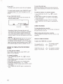
USE OF THE TAPE COUNTER
m bape ownbr i
TAPE MTURN/TAP€ R m R N PLAY
muletaw.
Tamthrmatapwtkul#poM~playh&
from a wd&mr polnt
n d m the ~
i runningW
timdthe~andtherelatiwpitionof~
Before sEarting r;ecorrling u m k , press CLEAR/
R E H 3 to set the counter to "*-.
By notlng the
wmtm reading at the d e s M pdnt, you can eaeily find
that point btm by refenlng to t
h canter, USB the IaM
on the
to List the progrems end M r m t e r
1 During reoording or playback, ptws CLEARjRESET at
the point you want to k a t e later.
2 When momling or playback b finished, stop the tepe
and press TAPE RETURN.
fhe
will be r m a m d or advanced close to the
p i n t w b r e the counter r e '0140-a".
TAPE
U
, RN
dings.
p
To atart playbck automatidy imm th~D
-
porh
P m
NoPso
The counter reeding is m b m t i d l y reset to zero
when e cambtk is newly inmtd.
The counter d i n g will be m i n e d in the mwngr
evenafterthepaweristunedoff,es~ssthe
cmsatte Is in the
com-t.
T h e counter will not a d v m U n g any
of a
tapitthmtisblankor~Soth~cern
beusedtoRndun~Eiecti~lsonatape.
PLAY after pressing TAPE RETURN.
TAPE
RETURN
The
and b
indicators light in the
window during
rewindim or
fast-forward nlmle.
Note
The tape mum and taw mum play cannot be
a b d when the ow*
reeding b within f
OFaOkQ98.
TIMER-ACTIVATED RECORDING
Up to six events can be set to be Fecwded on a oerterhr
day or e w y k y within
every week.
BEFORE
seven days, w on the cmme day
1 Set the positions of the selectws
curd!^ as on
pew 9.
2 Press TIMER SET.
The -am
nurntw (up to a p p a ~7'
. i n d m
that yw are making Me fmt timer setting.
THE
rnlnks sm'nllbely
Make sure that the clock (day and time) is set
cwrectly .
.&sure
s c a ~ ~ e twlthasalietytab
te
is inswkl in ths
cwnmment.
indicatcx in the window.
Check with the
.Select the recording tape s p e d C k k with the
u Wm indicator in h e window.
3 Set the day with the +or
- button.
set the tum-on h w r with the
w -button.
W e sure that AM w PM Is property set
AM 12:00=midnight
PM 12:00=noon
4 P r m NEXT end
';
*,m--m'
NaCTkrtDar
Ew
pmW nexbvdll Mink
"
,
.
-
s
m
.
.
-,
.
,,
5 Press NEXT and set the minute with the
htton.
*.-.ba
-
,
+
+ or -
,
I
+/-krtaorw
To set the day of the W,the time a d the channel,
press the f button to adv-,
and the -button to go
back.
Day lndlclatlon
By presslng fb+button, the day indication
follows :
Ex. T d a y is Friday.
(today) (tomorrow)
(everyday)
Sa
EVERY WEEK
6s
-
EVERY WEEK
Fr
EVERY M E K
To reoord at t
b same tirm every day, selset "Su Mo
Tu We Th Fr $au.
To recard at the
time and day every week, select
the desired day indication with *EVERY WEEK".
7 Press NEXT and B& the channel to be recwded with
or-^.
8 Preas NEKT.
TIM tape counter end the c w m t time will
---
To preset mother program, press TIMER SET @n
and repeat steps 3 to 8, Up to 6 programs can be
m.
B Press TIMER REG ON/OFF.
The p o w HJll b turn& off end the recorder will
entertbetanrlbymode.
Toreeordthewdbm
S t h e b m d f time to d l y the same tlme an the
t w n a time. Reoording will continue to the end of the
tape-
To
the memory of a p a f h h r progrem
t Press TIMER REG OPI/OFF. The
i n d m
tums off.
2 Press CHECK to select the program to be erascut.
3 Presdi CLEAR/RESET. The memory of the
will be eliminated.
4 If 0 t h m r a m s have been preset for r e d i n g ,
pregs TIMER REC ONjOFF w i n to reaciivete the
timer.
DURING RECORDING
Cutent time
To stop durlng the t l w mmdhg
P m TtMER REG ONJOFF. The recording will stop and
the power will be turned off.
Recording will start at ttw preset time a d will
autometlmlly atop when he mcding is eamplw.
~ ~ e m e m o r ~ d t h e ~ ~ ~ o e p t ~
~ ethentape
d m i a durlng ther recordlq
When
every week setting will be dand the propam
The bw sbw but the tape wlll not be rewound to the
psitiin the timer will m C 8 OM by W.
binning.
NOTESON n
the~cordercanbe
. To tun on the
m RE-W
TWwhmlWERIlECIspressed
The mssetb will be
automatically.
BEFORE THE TMER-ACtlVAm REQ
STARTS
TIMER REC does not
appear in the window.
check the tlw
Press CHECK. Every time you psess CHECK, m h
program will be displayed.
To
T
O
W the mhgs
1 Press TIMER REC ON/OFF. The
Indbtor
twns oft.
2 PrehKi CHECK to d m t the prcgam to be dmqed.
3 Prws f IMER SET.
4 Press NEXT untll the H
m to be chngd blinks,
5 C h m the settiw with the
or - button,
8Prw~
NEXT so h t the tepe cwntw md the current
+
time appear.
7 Press TIMER REC ON/OFF again to m t l v e t e the
timer.
0
The cassette inserted
h s the safety tab
removed.
No -8
is .-i
QUICK TIMER RECORDING
Use this functian to -in
reeding a program
immediately. You can start timer recording jmt by
pressing W I C K TIMER. The rearding duation can b
set for up b 5 hours by 30 minutes. You can also use
thia function to sop t
b non-timer M i n g by
p8mting the reoordlm dumbl.
By m i n g QUICK TIMER, you can set the duration so
that the recording stops and p o ~ turn
p ~ off after the
preset duration.
Once~qulcktimer~dhrghasaarted
Only the fdlowin~function buttons cm be activated :
QUICK TIMER.....to change recording dwation
TIMER REC.....to interrupt quick timer recwdlng
PAUSE.....to stop quick timer recording momentarily
CHECK .....to check timer programs preset
MakewreUWths-hm
1 Press QUICK TIMER.
fhepwerwllltmtrmedon.
SPECIFIC NOTES UN TIM=-ACTIVAm
RE-
I
Channel previously aeleetd
When the prrraettlngs of ywr timer-advated m m
owlap
There will be no erm indicatim to inform you of the
overlap. Even if thm is an overlap, a mading will be
made.
2Choosethecfiannel toberecwdedwitbthe + o r
button.
H yw do not advance to the next step within 3Q
seoonds, The power will b turned off.
will @ cut off
3 Press QUICK TIMER so that the recording starts.
Now decide the recording duration.
The recording of -am
is finished.
2 will begin befare prol;fam 1
UapwverMmWonoewrardukrgtirnerrecording
lfihsdodrdKrm"AMP:O[)"~bl~
When the recorder was In the standby mode, all the
timer mings is wased. Re& the c h k and iimr
setting.
W k n tho timer-recordtng was ectivaterd, lhe recoPdlng
will stop.
When the W i n g starts,the duration indidon
decreases minute by minute to 0:00 and the power wit t
be turned off eutomaticdly abut 30 secomk after the
reoarding has finished.
ADVANCED OPERATIONS
BETA HI-FI AUDIO RECORDING
T o m n e c t t h e V C R t o y w r a u d i o s y s t e m , ~ p ~27.
~e
Set the wlt&om rn shtmn below. To Mrecording,
inwt a cessette and Jde R€C to the right
Menually a d i d t
b recwdlng I d .
Set FlEC LEVEL w KI ttrat ffirst
red demsnt li*
up only at
the h b W signal kvd.
REC LEVEL
AUDIO MONITOR to H I 4
and m-A MOMTOR to
BETA
(c-1
ON
I
for manltorlng
the
be
INPUT SELECT
to UNE/PCM
IBH rn-
is recommended
for audio recording.
When recording from
an FM tunew, wt WX
FILTER to ON, (If p u r
FM tunw ha8 en
Internal WX fIlM,set
to OFF.)
By connecting an FM stereo tuner to the LINE AUDIO
IN jacks beside$ Um cable TV cable connecting, you
can record a cabb TV program with
swnd, such
as MTV (muslc TV), w4wse audio *gnats are divided
into the FM tuner from fhe cable.
For FM simulcast rwxfding, set INPUT SELECT to LINE
AUDIO. Only the sound from the FM tuner is recorded.
INPUT SELECT to L I E AUDK)
TIMER-ACTIVATED FM ECORMNG
Use an optional prwram tlmer to turn the audio system
on and off.
Audio system
The setting of the mtmk is the same as In
'RECORDING FROM YOUR AUDIO SYSTEM".
Set the recorder's timer and a p r w r m timer to the
same turn-on and turn-off time. The sethngs on the
recorder's timer are the same as in "TIMER-ACTIVATED
RECORDIMQ" on page 15.
PCM RECORDING AND PLAYBACK
Connect a PCM digital U l o processor
shown MOW.
PCM dloltel audb
our
to^^
II
$
to VIDEO OUT
~ O M M ~ M M
Amplifier
E& INPUT SELECT to UNE/PCM
and MPX RLTER/PCM to PeM, For optimum mul&,
use a video cwxWte with e model number of L-500 or
bet^ (L-2M1. L-125, &,) and ~ e ktape
t
F a detalls, refer to the inshctim manual fmished
For PCM d i n g ,
ma.
with the digltal audio procassor.
CAMERA RECORDING
When connecting e Sony color video camera, the use
of the Smy HVA-220 aa
is required. For details
on oannectim, refw to the instruction manual furnishEd
with the AC adaptor.
Nab
The- crtmera must conform to American TV (EIA)
stand&I.ds.
Nobe
If you Intend to playbWc on a VCR with t
b Suswitch set to 'OFF" or on 0 t h rwn-Superbta VCRs,
set the SuperBeta switch to 'OFF" w t m making ywr
PCM mcdinos. Otherwise, the sound may be m u t d .
EDITING A TAPE
m.
To edit a home movio w,you need two video
To st& recording, set the VCR for piayksk in the playbwh m d e , then press the record button on
the other VCR.
Another VCR
BETA HI-FI (rser)
A U M WIMFI to H I 4
and Hi-fl MDNITOR to
STEEO lor
mmltwlng the eound
b be r m d d .
To edt a home movle tqm from thr 8UJFSSO to ##ttm VQ1
- - ... - - -
E T A HI-FI to ON
SUPER BETA
to a,
Twn SHARPNESS
towrud SOFT a little
from the p R i o n you
use normally,
films, v i d a tepes and o h r
rnatwials may be oopyrighted.
U
m duplbath of swh m e i d may be
contary to the provk3icm of the copyright laws.
Television
to VIDEO lN
to A U W
Ud
Nom#llb& AUDIO MONITOR to HCFl and Hl-R MONlTOR to
STEREO. TOrecord the SAP sound wlth a monaural VCR
AUDIO MONITOR to NORMAL.
synchronization with playback startjstop on tbe
playback VCR.
Only the particular scenes
on the playback VCR
wlll be edited (automatic
ding). Reemding
atarthitop on the SL-HF550 can be d v a W in
AK-74AIBUpplw
b UNE A W l O
IN
Pnwt the daslrd m e 8 by the
To stad
set the SL-W650 In reoording mode
m u d d tha playbeck
editing.
and then f o l k the niVCR for the mtomtlc
m T h optimal RM€100/ElW vidw> edCtIng wntrdler
alleasier d i i n q bhwm two VCRn.
+The requid c a m d n g cuds memy d m depending
an VCRs. R d W to the inslrdw manual ol the VCR.
u e o o f t h s ~ S ~ i a d r
~fthis jeok is connecfed to the COWRUW)OUT jack
o f a S m y c o l w T V orlVtuner,~lsmcanhrcanbe
mtrolled by polnting tha supplied RMT-131 Remobe
~toweFd~remoeesensoron~orllorfV
w TV turn,
Note
AvoW repetition of edlting taps, a ~ the
i
pickre and
tone quality will be impaired n o t i d l y for newly e d M
Before making oonnecthw
mTum off the TV.
Do not connect the ac power cord until all the
connections of the video recorcter and the TV have baen completed.
r Make the connections firmly. 1connections
may cause a distorted picture-
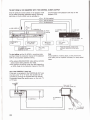
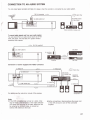
ANTEMNA/GABlE AND TV CONNECTION
Disconnect ttw T\I: anhna cables from the TV receiver
and connect ttmm to the recorder. Then connect the
recorder and the TV.
Use the removed separator to connect the r m d e r and
the lV.
Most combination antennas are equipped with a UJV
band separator (signal splitter). Take off the separator
and connect the cable directly to the recorder.
F-type connector
U/V h
d
separator {optima%
J
AJ&
'Uw an optloml RFCB axtension cable, Bin (25 ftl IonQ, I f the supplied
If you need a separator or a complete antenna system,
sea your SMly &la M a qualified technician.
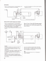
When the cable Is a m h r n
75-0hm coaxial cable Is not
Wen the cable is a 7 W h m
EAC-26
antenna connectw
(suwlW)
enough.
an optional E A W U/V band -or
VHFjUHF OUT connector of hrecorder.
1 Attach
to the
2 Connect the sepmtm to the VHF m d UHF antenna
terminals of the W ,
C
CP
E A G 2 5 antenna ci...
wplw
both VHF and UHF andemes are c m m c W ]
AtCach en optionel E A W U/V band sgparator
(mixM to the VHF/UHF IN conof the w .
Connect the antennas to the U/U band -tor.
Attach anoptional U/V band mpamtw to the
VHF/UtlF OUT m e c t o r of the mwdw.
4 Connect it to the VW and UHF antenna terminals of
the TV.
W h e n a 7 V h a s a 7 ~ W / V H F m ~ ~
Emy connection d the recorder to the TV can made
with a supplied 7-m
coaxial cable regardless of the
types of antenna
UHF
Cardkn
m e e n the FecMder WIF/UHF OllT
m m t w and the antenna taminah of a TV
recevier should be m d e only ES sbwn In thee
Instructions.
Fallwe to do so may mutt in operation that vlolmh
the regulation of the F
m Cmmunicahm
Commbsion m i n g the me and operatton of rf
Conn-
devices.
Never can&
the autput of the recorder to an
antenna u make sirnuWellel) mtmne
and m c m k mnection at the antenna termids of
your receiver.
24
Once the eonneetiexplaind W havs h e n
m d e , the antenna lV signds, as well as the signal
fromtherec~,willbefdtotheTVandyoucan
view TV p g m m in the usual way.
Mow
K w the VCR m y from the TV, if the disp@ or
s o d is affected.
~
e
~
~
make s m #tat the cable le WWY
omwebd.
y
WhanmNknobscabteTVEorapatY#etrpe
the
Connect the cable lV channel cmvester
remrdef and the TV so that you can watch a
n
o
w
w
t
o
~
cable TV program while recording one cable TV
program.
T V M R button is set to TV.)
Note to CATV sysbm W a k r In t)ll U. W A
This reminder Is provided to call the ceble TV system
Installer's M i o n to Article 820-22 of the NEC that
providee guidelines fw proper grounding and, in '
particular, specifies thet the cable m n d shall be
connectd to the grounding system of the building, aa
close to the point d cable enby as practical.
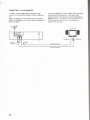
3ww!r!4 twin lW
Connect the lead-ln wtre.
2
Pass th. ring our cable.
3 mm ph inch)
75-ohm c m l a l cable
~
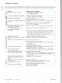
~ E c T w AGCOLOR Y M 0 R
To~nabethqudityp~,oonnectaoolor
monitor. such ES the &ny Prowl Trlnltron Component
lV.
When a compment TV is combined with the apa&cw
recorded with
8ysWn ss illmtmtd, yw c m enjoy
El& hi-fi atma.
To use e component TV tuner togewith the m o n k ,
&etbaamecmnectionaainthecaseofth
reearder
the conventional W receiver described on
pa0os23and24.Fordatmilsonths~hofthe
TV tuner and the monitor, refer to the instwetion
m m W of the lV luner.
Component tV
CONNECTON TO AN AUMO SYSTEM
You can mby tepecp recwded wtth Beta hl-fl stww when the recorder is c
o n d ' t o y w r audio eystem,
e
sign& flow
St-
amplifier. ream,etc.
-4.3 .
To~drwrdisdmalsonlyfromywrwdk~
You can record from an audio source such as an f M
tuner, CD player, with the Beta hi-fi system w i W
M l n g v i h signals.
W player
An,
FM iwer
-01
to V I E 0 OUT
\
[
to LINE
AUDIO IN
to UINE AUOO OUT
4
&'
--
1 I
-
S i a l Plow
(11
v
Component TV
W
1
m
.
~ q ( j I c ;
a h
ner w ra radio, noisa
In this GWB, keep the
radio, adjW the AM
external AMaWmaboUmtuner.
B e f o r e connecting or dlarc#lnecti#l~
oftheVCR, t m m m t o t w n o f f t h s c o n ~
amplifier.
card
AWUSTlNG THE XV
Your TV receiver must be adjwtd to recelve the signal
from your recorder. tf you connect a color monitor, it
does not need adjusting. ,
PQWER
1
/
@ Set RF UNIT located in the tuning compartment to 3 CH
ar 4 CH whichever channel is not active in your area
I
@ Press POWER. The tamp lights.
@ Prerss TV/VTR
to display the
Vl7 indicator In the wlndow.
@ Chmk that INPUT SELECT is
set to TUNER, then select an
active channel in ywr area
with the +/- buttm on the
reccder.
@ Turn on the TV,
r w e h to either VHF channel 3 or 4 to agree
with the RF UNlT setting.
Ttm TV program m e d on the m d w or the tape
w a r n wtll be displayed on the lV screen. If a picture
on the lV screen oi if the display is not
does not
clew, fine-tune the channel m the TV.
F u details abwt TV channel adjuslmmt, s e i the
imhtctlcm manual of the lV meek.
@
Set
I the fV
I
Check that the pro~rrtm
dbplayed on the screen changes
when a different channel is
selected on the m,
If the
p r o O r a m ~ ~ ~ g e , W
Check that the display on the
screen change6 when yuu m p
the
by pressing W STOP an
t
b recorder. (To eject t
M
cmette, p m s 6 EJECT.)
If the progrem does not change,
repeat the preceding steps.
your lV m e *
is tuned to the recarder.
Wlwnwer you use the video mmiw, you shwld set
the TV to th-a channel which you haw d w m n dmve.
Now
S t N G THE CLOCK
When you connect tbe AG power ad tO a M I outlet,
the ctmk indhtes FSau AM lmy.W
# wlrvltl bllnk to
CLOCK SET
3 Press NEXT.
1 P m CLOCK SFT.
Set the day with the f or - button until "We"
appears.
Set the minute with the t or - button until
'PMSW appears.
4 Press NEXT.
2 Press NEXT.
(For accurate setting, press NEXT at the s u m time
with an annwncd time signal.)
The clock will now show the current time.
Set the hour with
the t or - button untll "PM3:W
s
p
m
.
AM 12:00= midnight
PM 12:W= nmn
The dots of the colon ( : ) alternately
blink evary 30 sezonds.
+/-&wm
The+ and- b u t b m c a n t m m d i n t w o w a y s :
m,
When you keep a button
the dbib will
advance continuously unit the button is m k s 4 .
When you peas and immediately releerse a button, the
dbts wHI M n c e by me.
PESElTlNG THE ACTIVE CHANNELS IN YOUR AREA
Y o v recorder is m
e
l of m i n g VHF chennela
2-43,UW channels -1
and ceMe TV chmnels
l~(AtoW),~(w+30toW+50)and9&125
(A-2toW+&l).8eectrennelrnanpeoe31.
Youcan~f4chnneCssohtontytWdeai~
channels will apptxw in
when you s8I-t a
channel Iakw on.
AFT w
W
;
F
C
E
lA
R
1 Open ttw tunlng compartment on the top of
CHANNEL
the
recorder.
2 Turn an the reoorder and the TV.
Make w e that ttm TV is wt to the c m t channel
{channel 3 or 4) for the recorder.
3 Set the INPUT SELECT switch on the recorder to
TUNER.
4 Pmsa TUNING
t m.
The first channel appadng on the swem will k
memized.
'7
Lights when SET
\"""':I::
If thls Is not tha channel you wish, r e p d
-.
prmlng 'TUNING t or
Every tlm yw press
TUNING, a hlgh-numbered c h n e l will be tuned
In by presalng t, and a lower-nuchannel
5 Ch&qethe number displayed at the far right of the
window to lndlcate the actual channel number
m l v e d (oreny number).
Press 'CHANNEL 10" (in the tuning compartment) to
chenge the tens-digit disptay.
I n d i i the band In which
channels am belng tuned In.
Mhtea the m x 1 m
I
Actual ohannel
numb# or any numbw
tolmd@ayed.
locationofmchanr#l
m n s d in i b bend.
2 Select a channel memwy podtian with the
CHANNEL
or - button on the front of the
murder fw the h i r e d channel to be tuned in.
3 P m s CLEAR.
The channel numder display will be changed to
u
"and therecorderIsreSabothebwd
f i G k c y of the VHF band.
+
P m e 'CHANNEL 1" (in the tuning corn-)
change the unitsdi~itdisplay.
to
Emy time "10" is pre#ed, the display changes
Blank-.ld2-.3
9-tBIankI +2 .....1Q
CATW CATV CAlVCATV
t
.....
€my tlm 7" Is
Blrk+O+l+2+3
m.
the display c k w x
.....9
6 R e p a t steps 2 b 5 for
positions to be preset.
7
SET.
The "TUNE"indicatw d.-l
o t bd
m
d memary
C A U IV CHANNEL CHART
t PflBSsEf.
The "TUNE' i n d i m will appm in the windcnn.
2 Select the channel b ~~~M m
f
h
e
CHANNEL w - ~ t h e f r m t d t h e & ~
+
m
-
e!
3FmmCLEAR.
The channel
.,YL-~>
w
A
"'
4 -SET.
The T U N .
d+rr
Now htxtmMdchsnnel w l H h a k l ~ v v h e n
either the CHANNEL -t/- buttom on thil W e r or
mfhe~-h3pmwed.
UP
TO w
m A WEAK STATION
1
Cable TV systems use letters w numbers to designate
channels. To tune in a channel, refer to this chert
-
r, .A .
.
*
*'
If the p b b e of a particular c h w l la rsot
,wtAFTtotlwOFF~ltionand~-t
unWi ttm piaure beccmes clearw. When
viewlngithla p&tcular channel, do not set AFT to ON.
F
Q
H
l
J
.-
K
.-
L
M
N
mIaclt(2)
rTW*Pthan47 kluwm
Phone iaek (2)
-10 d8s
u=bb-
mn: na
Wt: 1
B am/-.
--h
Am: 3 bm #, mln.
m a -
(nmhmLg30F s r t - t m mui rewhd thm
hplxox 9 / 2 mhcdooi
Audk--
WnhUIOFF
m1: B W p o o l-k
w.: aa7,m Hx
6etahMIONWXFllTEROFF
\hbw and k l W
Dvnmb
mn,
BetahMION
krth.nmWRM5
mhUi ON
mttw80dB
A
a s = O . T I S V rmd,
-
maurn0
rm w
Q
-
V l d m o ~ ~ t u iR nu t a r y l w h d h d i c d ~ l n g
Audlo mdkrp gretm 06ta hl-fi ay%tm (2 -nab)
(Fkeordhgonth.~audbtmlIin
u A ~ , M S C c d #
~swsthwhsvln~mmerkm
m~ mrr:4a m / = ~ l y PWW
P
CkhwiththrkalcabteTVcompanyfarm
c m p h b information an the available channds.
*fhe desigrmtion of#a cable TV channel8 canfwm
to the EIA/NCTA m m e n d a t i o n .
Noee
Payxycablelv~usesuamMeduenooded
signals and require m i d mw&m ( d m ) in
raddifion to the normal cable cmnectlwl.
wmm
VWeo awl
O
- l D # s ( a t l o a d ~
47 klbasthan10 k t m m
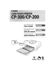
Thmrelbn
Ckck
~ i w m h p r m e r
mmRdlca#on
r ta
Qmnl
hr~qulrsmsnts
-Ewwmptkn
m r n twm-tunmatwe
-
Dimwrwls
WlpM
-
12Gyde
onryto~~~nd~recordir~g
6
can
sst wlttth 7 days
n g
laW ae f1%
BE to 40%
S3 Hz *&6%
Wf'F to m7=)
-20tCtofBOT)(-4'Fto+1&F~
A p p o ~430XQ6YWmm(w/h/d)
07 x 3%x 14% M m )
Wl. mbotlng patGs and ~
~
~ p r o x . 9 . 2 k o W b lor)
1
3
bmM.Bl
R m t Eontrot syutuinMand miml
C#mrartdmok
m-1
Pwwrwkrmonh
3Vdo,2dmMbaft#lw
(IEC dmlpnaml RB)
DbwWma
Appron. 44 X 2Q X 176mm (w/h/d)
n k x % x f ~
M*mwWP-d
comolo
Wmbhf
~ x . m ) g p . 9 w ) ~ ~
A-rppkd
-7
OWMW wlth F*
C
@rn,Bf@)
1
Antenna oonnletw EAC-26
1
conmthg Eord FIK-74A
1
C m w RMT-a url(h W
M-
........................
....................
.....................
. . . . . . . . . . . . . . . . . . . . . . . .1