1
‘ llllllIllllllllllllllllllll
llllllllllllllllllllllllllllllllllllllllllllllll
US005144441A
D
United States Patent 1191
[11] Patent Number:
Sparks et al.
[45]
‘
Date of Patent:
[54] QUIETING RECEIVER DURING POWER
INTERRUPTION
Sep. 1, 1992
OTHER PUBLICATIONS
_
CTC 140 Color TV Chassis Technical Training Man
[75] Inventors‘ Bradley A‘ Sparks; Robert E- M01115’
both Of Indianapolis, Ind.
[73] Assigneez
5,144,441
ual, ?rst published by GE Consumer Electronics, pp.
3449’ 1987_
Thomson Consumer Electronics, Inc‘,
SL-HF750 Operation Manual, published by Sony,
IndianaP OHS , Ind.
Aug, 1986, pp. l27—131.
Primary Examiner-Tommy P. Chin
[21] Appl' No‘ 3271880
[22] Filed:
Mar. 23, 1989
Attorney, Agent, or Firm-Joseph S. Tripoli; Joseph J.
Laks; Haw” D- Fned
[51]
1111. (:1.5 ............................................. .. H04N 5/63
[57]
[52]
US. Cl. ............................ .. 358/190; 455/343
A receWf-‘I COIPPYISBS 8 “met 91"?" for detectmg *1
[58] Field of Search .......... .. 358/190, 189, 198, 191.1;
_
_
ABSTRAC?
_
_
§e1ected mp)“ 5181131 W1 an audlo Cm?" for reproduc
455/343, 135, 186
mg the audio content in the detected signal. The tuner
References Cited
circuit includes a local oscillator, a prescaler, a phase
detector and an integrator, and has a tendency to un
us. PATENT DQCUMENTS
controllably detune during AC power interruption re
[56]
3,882,400
4,031,549
sponsive to a spurious tuning control signal generated in
5/1975 Hamada ............................ .. 325/456
6/1977 Rast et a1. ......................... .. 358/193
the tuner circuit and generate audible noise during the
damning The audible noise is introduced into the audio
"
4,227,257
10/1980
Sato . . . . . . . . . . . . .
4,355,422 10/1982 Paschen
4,405,947
4,532,457
content of the detected signal. An AC power interrup
. . . . .. 455/343
“on detector momtors a r“? Power supply and gene”
‘‘‘‘ __ 455/343
ates a power loss control signal when the run supply
9/1983 Tults et a1. ..................... .. 358/1931
7/1985 Haferl ................................ .. 358/190
falls below a pr?determmed threshold A control clrcult
responsive to the power loss control signal, absent a
4,546,388 10/1985 Williams, Jr. ..
4,641,064 3/ 1937 Twin 61 a1
user command, ?rst disables normal operation of the
tuner circuit and then disables the audio circuit, thereby
reducing the audible noise. The tuner circuit may be
disabled by decoupling the output of the phase detector
4,641,190 3/1987 Test?" e1a1~
41656399 4/1987 Team et a1
"
4,716,463 12/1987 Stacy et al. ....................... .. 358/190
4,743,864
4,750,040
5/1988
6/1988
4,763,195
8/1988 Tults ............................... .. 358/193.1
from the input to the integrator, enabling the input to
Nakagawa et a1. ............... .. 455/343
Hakamada ............. .. 358/190
n
h
b
f
.
.
I f
h
‘1 t e a Sen.“ 0 a comctwe .s‘gna .‘om ‘ 6
Phase detect“, whlch may be the Spunous mmng con
trol signal, the integrator maintains a substantially con
stant output tuning voltage and prevents sudden detun
FOREIGN PATENT DOCUMENTS
0183334
I
Oat'
ing.
6/1986 European Pat. Off. .
49-131336 12/1974 Japan .
25 Claims, 3 Drawing Sheets
1417794 12/1975 United Kingdom .
TO OTHER RUN LOADS
6
- so
STANDBY POWER
roruusn
18
i
xmomo wmnx
mo mmcnoas
97
1 54} 1! has
1s
TINT
-+co|.on
@c-v CONTK’L
I
SYSTEM <7:>
_
15
12
I F—
TOJAQG PANEL
w’ am
roman A
25,_
s
$3
i
12%?
PHASE
L11» 0 us
V L“
19
T0 AUDIO
BPULSES __>EQԤQNCE pnocessmc
T0 emu swrrcH ‘——’
H
41
'E'JUT‘EE
4,
—>ROSD
fLo/K PRC
AUDIO AND VIDEO
m
“m?
sameness 10m
I
vmeo
—>Aurocoion P
55“;
MU
1s
‘(U
17
BASSTRELE
cnmua was nuts
42 AUDIO
t t
333;?‘ “ AUDIO
, AuP +PREM‘P
‘6,
+ ,
AUDIO CONTROL
‘1
1st
amt
came __1 11x1
AUDIO
.._..
‘_
D
VOL EAL
__}Aux 2
<———-———-
AUDIO ou1{<———-
H
t
'4 M 3
FROM SYSTEM 001mm
as
US. Patent
Sep. 1, 1992
Sheet 3 of 3
5,144,441
FIG. 3
SYSTEM
CONTROL
+5V
STANDBY
FIG. 4
SYSTEM
CONTROL
5,144,441
1
2
loop is necessary due to frequency offsets of the RF
carrier produced by cable systems, video recorders,
QUIETINC RECEIVER DURING POWER
video games, computers and the like.
INTERRUPTION
This invention relates generally to the ?eld of divi
sion and radio receivers, and in particular, to techniques
for quieting television and radio receivers to prevent
random noise generation during interruption of AC
5
Typically, the microprocessor is powered by a
standby power supply, and is therefore always turned
on when the receiver is plugged into an active AC
power.
power outlet. An analog interface unit, for developing
analog control signals responsive to digital control sig
nals generated by the microprocessor, receives a
power on remote control circuit. Most receivers are
Manual, ?rst published by GE Consumer Electronics,
therefore provided with standby power supplies, which
at pages 34-39.
continue to be energized by an AC power source even
In many such synthesizing tuning systems, audible
noise may be generated and propagated through the
Many television and radio receivers, including those 0 switched standby voltage. The source of power for the
analog interface unit is also the standby power supply,
found in video recording apparatus, are provided with
but the analog interface unit may be switched off to
digital tuning and control circuits. Many of these re
reduce power drain when the receiver loses AC power.
ceivers provide for storing program information and
Other portions of the tuner control circuit, for example
preset tuning selections, and many are provided with
the prescaler, are powered by a run power supply cir
remote control. Some provision must be made for main
cuit. One version of such a tuning system is described in
taining such information in memory during periods
the CTCl40 Color TV Chasis Technical Training
when the receiver is turned off and for energizing the
when the receiver has been turned off. Standby power
supplies are intended to provide just enough power to
audio ampli?cation system whenever a channel is
changed. This sound of static, which is sometimes re
ferred to as a crashing or popping sound, is generally
maintain the power on circuit and the stored informa
tion, for example the information contained in the ran
dom access memory of a microprocessor based system 25 not harmful, but is considered to be very undesirable
control.
_
and unpleasant. Accordingly, the microprocessor
.
which controls channel selection and tuning is fre
quently programmed to mute or turn the sound off prior
to a channel change in order to prevent the propagation
of such audible noise. The video signal may also be
Such receivers may be provided with synthesizing
tuning circuits for receiving user selected broadcast and
cablecast signal transmissions. Synthesizing tuning cir
cuits are disclosed in detail in US. Pat. No. 3,882,400,
blanked. After a new station has been tuned in, the
which also discloses muting during channel change, and
U.S. Pat. No. 4,763,195, which also discloses autopro
gramrning.
sound and picture are restored.
However, there are certain operating conditions of
age controlled local oscillator stage. Tuning is accom
loss of AC power, for example when the receiver is
such receivers having synthesizing tuning which result
Synthesizing tuners are frequently embodied as
varactor tuning systems. A typical varactor tuning sys~ 35 in undesirable noise which is not eliminated by muting
during channel changes. A cause precipitating these
tem'has three stages that must be tuned. These are the
operating conditions is the unexpected interruption or
radio frequency RF stage, the mixer stage and the volt
plished by varying tuning and band switching voltages.
unplugged or when a reduced power condition occurs.
The tuning and band switching voltages are supplied
This prevents the microprocessor from running those
from a tuner control circuit. Most tuning systems utilize
programs which would otherwise be utilized to turn off
the receiver quietly responsive to a user control. The
integrated circuits.
A typical tuning system is a frequency synthesis type
having a crystal controlled phase locked loop. Phase
problem of unplugging the receiver becomes more
widespread as more receivers become plugged into
pulses are produced by comparing a sample of the tuner 45 cable control boxes rather than directly into AC outlets.
Turning off the cable control box then becomes equiva
local oscillator signal to an internal reference fre
lent to unplugging the receiver.
quency. The number of pulses, or sometimes the width
Tuning circuits as described herein have been the
of the pulses, is proportional to how far the local oscilla
source of several problems during their introduction
tor signal is off frequency. The phase pulses may be
and more widespread use, and solutions to these prob
applied to an integrator, for example, to develop a tun
lems are of someinterest. A phase locked loop tuning
ing voltage for controlling the frequency of the local
system for a television receiver is described in US. Pat.
oscillator. Varying the number or width, and polarity of
No. 4,110,693 and includes a frequency divider for pres
phase pulses adjusts the tuning.
caling the frequency of a local oscillator signal gener
As part of the tuner control circuit, a sample of the
tuner local oscillator signal is supplied to a tuner pres 55 ated by a control oscillator. A lockup condition some
times results from an uncontrolled and erroneously high
caler. The prescaler is a divider that generates a divided
down local oscillator signal. Dividing down the local
oscillator signal produces a low frequency sample and
self oscillation of the prescaler. A lockup inhibiting
arrangement is provided for causing the controlled
permits the use of a low frequency reference, or com
oscillator to temporarily oscillate at a frequency for
parison signal with the reference signal in the phase
locked loop.
suf?ciently high to overcome any self-oscillation of the
There are effectively two loops in the tuning system.
The ?rst is the phase locked loop which locks the fre
quency of the local oscillator signal to the crystal de
whenever the receiver is initially turned on or when a
channel in a new band is selected.
which the amplitude of the local oscillator signal is
prescaler before phase locked loop ‘control is enabled,
“locked”, AFT and sync are checked and used in the
Some of the ?rst synthesizing tuning circuits were not
precise enough for fine tuning, and some were a source
second loop to ?ne tune the local oscillator by changing
the value of N in the divide by N circuit. The second
of noise even during normal operation. Accordingly,
such synthesizing tuning systems were used only for
rived reference signal. Once the phase locked loop is
65
5,144,441
3
coarse tuning and thereafter disabled. An analog auto
matic ?ne tuning circuit was then utilized to maintain
4
processor are bypassed when the converter box is
autoprogramming, even for stations cablecasting signals
switched off.
The problem was not solved merely by detecting the
loss of AC power and muting various parts of the audio
circuit. The various ampli?ers and circuits in the audio
system have many capacitors, and respond with a rela
without picture synchronization components, tuning
tively slow time constant. Even if one were to very
the channel selection.
_
More recently, a dual search mode tuning system was
described in US. Pat. No. 4,405,947. In order to effect
promptly detect the loss of AC power and generate
the input of an integrator generating tuning voltage as
those signals necessary to mute every mutable element
an output. One source is the phase locked loop, includ - 0 of the audio system, the muting would not take place
ing the prescaler. The other source is the automatic ?ne
quickly enough to suppress the noise generated by de
tuning signal. Each source is an input to a mode control
tuning of the phase locked loop responsive to the unex
switch.
pected loss of AC power.
It is a characteristic of some receivers with standby
A television receiver is described in Us. Pat. No.
4,641,190 wherein a blanking signal is generated when a
and run power supplies that, when AC power is lost,
channel change selection is made. The blanking signal is
run power supplies will drop before the standby power
low pass ?ltered and thereafter controls the muting of
supplies are affected, for example by approximately 50
milliseconds to 100 milliseconds. This makes it possible
the audio channel. Muting and unmuting are thus ac
complished gradually, without audio disturbance. The
to continue utilizing the microprocessor and the analog
tuning voltage is allowed to change to the new ,value 20 interface unit for generating additional control signals
required only after a delay period following the start of
to suppress the audible noise resulting from abrupt de
the blanking signal. Muting is therefore substantially
tuning due to AC power interruption.
alternates between two sources switchably coupled to
complete before tuning transients can occur and cause
It is an aspect of this invention to suppress the genera
audible noise.
tion and propagation of audible noise due to AC power
Circuits are also known for detecting the status of a 25 interruption in a receiver having a tuner circuit and an
power supply in a receiver and executing a control
audio circuit. The tuner circuit includes a local oscilla
sequence of commands responsive thereto. In a televi
tor, a prescaler, a phase detector and an integrator inter
connected for tuning the receiver to a given or selected
sion receiver environment, for example, US. Pat. No.
channel by detecting a corresponding input signal. The
4,641,064 describes a power supply which generates the
normal operating level of an energizing voltage. An
tuner circuit has a tendency to uncontrollably detune
overload detector generates a ?rst control signal to shut
during intermittent AC power interruption responsive
down the power supply and remove the energizing
to a spurious tuning control signal generated in the
voltage when an overload condition occurs. A control
tuner circuit and generate audible noise during the de
circuit periodically samples the level of the energizing
tuning, the audible noise being reproduced together
voltage. When the level is lower than normal, the con 35 with the audible signal. In accordance with this aspect
trol circuit generates a second control signal that main
of the invention, the AC power source is closely moni
tored by a circuit which generates a control signal dur
prevent the power supply from attempting to restart. A
ing conditions indicative of AC power interruption. A
third control signal inhibits the generation of the second
further circuit is provided responsive to the control
control signal when an input alternating current voltage 40 signal for disabling normal operation of the tuner cir
that supplies the power to the power supply suffers a
cuit, for example by disabling the tuner control circuit,
voltage drop or brown-out for only a short duration.
and for disabling the audio circuit, thereby reducing the
Similarly, run power supplies have been monitored as
audible noise during AC power interruption.
an indirect indicator of an overload condition, for exam
In accordance with a further aspect of this invention,
ple as described in the CTC 140 Color TV Chassis
the further circuit disables normal operation of the
Technical Training Manual. An overvoltage X-ray
tuner circuit prior to disabling the audio circuit. This
protection circuit disables the run supply. Detecting the
eliminates the tuner as a source of audible noise as the
loss of run power results in the television receiver being
audio circuit cannot be muted quickly enough to pre
turned off by the microprocessor.
vent propagation of that noise which is generated dur
Despite all of the developments in connection with 50 ing detuning.
tains the power supply in the shut down mode so as to
synthesizing tuners, a vexing problem has persisted, and
In accordance with yet another aspect of this inven
tion, the tuner circuit is disabled by decoupling the
power supply which powers the prescaler in the tuner
output of the phase detector from the tuner control
circuit falls below a threshold value, the prescaler will
circuit.
operate abnormally and output a very high frequency 55 In accordance with still another aspect of the inven
signaLThis signal is presented to the input of the phase
tion, and more particularly, the further circuit disables
locked loop tuning system, which develops an output
normal operation of the tuner circuit by decoupling the
indicative of an abrupt channel change to a lower fre
output of the phase detector from the input to the inte
quency signal. The phase locked loop output to the
grator generating the tuning voltage, which in turn
integrator causes the tuning voltage to fall rapidly. The 60 controls the local oscillator. The input to the integrator
effect of this detuning causes the RF automatic gain
is permitted to ?oat. Without any corrective input, the
control signal to increase, together with the tuner gain.
output of the integrator, and therefore the tuning volt
The resulting abrupt detuning generates an undesirable
age, will tend to remain the same. Although some ran
and perceptibly loud sound. The increasing use of cable
dom variation or ?oating of the tuning voltage is likely
and satellite converter boxes, having AC outlets into 65 to occur, the frequency of the local oscillator will not
which many receivers are plugged, signi?cantly in
change abruptly. Despite the floating and somewhat
creases the incidence of AC power drop out behavior
random variation, such minimal detuning as actually
because power down control routines of the micro
takes place is usually insuf?cient to generate any appre
which until now has not been solved. Whenever the run
5
5,144,441
ciable quantity of noise. This approach is particularly
6
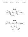
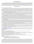
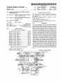
The tuner circuit is shown in more detail in FIG. 2
and generally includes a tuner 22, a tuner control circuit
24 and a band switch 26. The tuner control circuit 24 is
effective because it addresses the very source of the
problem, namely the spurious output signal generated
part of the analog interface unit 14. It will be appreci
by improper operation of the prescaler when the run
power supply drops out. The muting which occurs
from disabling the audio circuit is at least effective to
reduce noise generated by the power supplies them
ated that the division between the tuner and the tuner
control circuit is to some extent a matter of de?nition.
selves falling out. It is not possible to eliminate such fall
out noise entirely, but it is possible to reduce the level of
municate with one another and with remote circuits
over a single serial data bus 15, illustrated schematically
as a number of separate branches. The output of infra
The various parts of the digital control system com
noise so as to be unobjectionable under most circum
red receiver 20 for the remote control unit is monitored
as an input to analog interface unit 14. The serial data
stances.
In accordance with yet another aspect of this inven
tion, a circuit for detecting AC power interruption may
comprise a circuit for comparing a ?rst voltage level
generated by at least one run power supply with a pre
determined voltage level. In one embodiment, the pre
determined voltage level may correspond to a second
bus is typically three lines, designated DATA, CLOCK
and ENABLE, as shown in FIG. 2.
The system control microprocessor 12 scans the front
panel keys of the keyboard matrix 18 and monitors for
a keypress. When a keypress is detected, the micro
processor determines which key has been pressed and
initiates an appropriate program sequence Scanning of
voltage level generated by the standby power supply.
In another embodiment, the predetermined voltage
the front panel keys or buttons is also used to drive the
level may correspond to a second voltage level gener
front panel indicators.
A crystal oscillator 72, for example 4 MHz, as shown
ated by the at least one run power supply in an energy
storage device, such as a capacitor. In either embodi
ment, the circuit may comprise a transistor, the control
signal being generated by switching of the transistor.
In accordance with yet another aspect of the inven
tion, the control signal from the AC power interruption
in FIG. 2, is used to generate a clock for timing the
analog interface unit and the microprocessor However,
25 the serial data bus may run at a lower frequency, for
detection circuit may be applied as an input to a micro
processor powered by the standby power supply. The
example 125 RH. This is generated by the microproces
sor 12 dividing down the 4 MHZ clock signal The EE
PROM 14 stores information for operating and tuning
the receiver.
microprocessor may comprise means for generating a
An AC power source is used to energize at least one
?rst command or control signal, for example a PLL
standby DC power supply 30, and indirectly, to ener
control signal, to disable the tuner control circuit and a
gize at least one run DC power supply 32. The run
second command or control signal, for example a
power supply 32 may be energized by operation of a
MUTE control signal, to disable the audio circuit. The
horizontal de?ection circuit 28, through a ?yback trans
audio circuit may comprise ?rst and second sets of 35 former. The details of such horizontal de?ection cir
ampli?ers, in which case the microprocessor may com
cuits are well known, and are omitted from the draw
prise means for generating a ?rst or command PLL
ing. The analog interface unit 14 provides power on/off
command signal to disable the tuner control circuit, a
control to the run power supply 32, digital control of
second or VOLUME command signal for quieting the
picture and audio circuits, on-screen display control and
?rst set of ampli?ers and a third command or control
tuning control. The microprocessor receives standby
signal, for example a MUTE control signal, to disable
power, even when the receiver is turned off. The analog
the second set of ampli?ers. It is preferable that the
interface unit may receive switched standby power
microprocessor disable normal operation of the tuner
from an on/off switch 34, which monitors the output
circuit prior to disabling the audio circuit, in order to
voltage levels, for example +5V DC and + 12V DC, of
prevent the generation of noise from abrupt detuning in 45 the standby power supply 30.
the ?rst instance. The microprocessor may disable nor
The analog interface unit 14 may control the video
mal operation of the tuner circuit by generating a com
and audio using a method referred to as quasi digital
mand effective to decouple the output of the phase
control. The adjustments are so designated because the
locked loop from the input to the integrator.‘
actual adjustment is performed by varying digital pulses
The invention is described in connection with the
that are then integrated or ?ltered to generate analog
accompanying drawings, wherein:
control voltages.
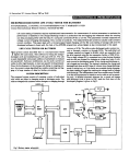
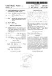
FIG. 1 is a block diagram of a television receiver in
Under normal circumstances, the system control 12
recognizes a signal from the keyboard or infrared re
FIG. 2 is a block diagram of a tuner and tuner control
ceiver to turn on the receiver. A control signal is gener
circuit for the receiver shown in FIG. 1;
55 ated through the analog interface unit 14 to the start
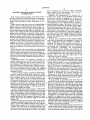
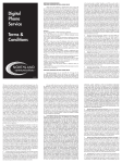
FIG. 3 is a circuit schematic for a ?rst AC power
/initialize circuitry 36. This starts a process which in
cludes energizing the horizontal de?ection circuit 28.
interruption detector; and,
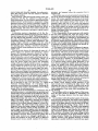
FIG. 4 is a circuit schematic for a second AC power
One or more secondary windings of the ?yback trans
interruption detector.
former in the horizontal de?ection circuit may be used
A television receiver incorporating the invention is
as a source of run power supply voltage, being ener
accordance with this invention;
shown in block diagram form in FIG. 1 and designated
generally by reference numeral 10. The receiver 10 is
provided with a digital control system. The digital con
trol system comprises a system control microprocessor
12, an analog interface unit AIU 14, an electronically 65
erasable and programmable memory EEPROM 16, a
keyboard matrix and indicator unit 18 and an infrared
receiver 20.
gized by the trace or retrace voltages magnetically
coupled through the ?yback transformer. During oper
ation, the analog interface unit continually adjusts, as
necessary, a plurality of signals 17 for controlling video
processing and a plurality of signals 19 for controlling
audio processing. Of these sets of signals, the volume
control signal on line 21 may be utilized directly in the
invention.
7
5,144,441
The audio control circuit 38 receives a demodulated
IF audio signal from a dual IF/demodulator 40 on line
8
verted from parallel to serial format. The converter 60
is connected to a shift register 62, for example an eight
bit shift register. The shift register 62 forms a data buffer
between the converter 60 and a parallel data bus 64.
Parallel data bus 64 is routed to each constituent circuit
of the tuner control circuit 24 which is controlled or
41, and derives therefrom left and right channel audio
signals. An audio switching circuit 42 is controlled by
the system control and an audio preampli?er 44 is con
trolled by the analog interface unit. The left and right
channels are coupled from the audio switching circuit
monitored by the microprocessor. All eight bits may
42 to the audio preampli?er circuit 44, and from there to
not be necessary for communicating with each constitu
the audio power output ampli?er 46. The audio signals
ent circuit, notwithstanding the general and schematic
may also be output to an external ampli?er or recorder.
representation.
Moreover, auxiliary audio inputs may also be accommo
dated. A SPEAKER MUTE control is generated by
the system control for muting the audio power output
ampli?er 46, over control line 25. The audio power
output ampli?er 46 drives speakers 48. In a television
receiver equipped for stereo sound, each of the sound
channels will typically represent a 5 watt dynamic
audio load. An interruption of AC power also adversely
affects the audio preampli?er and audio output ampli
The constituent circuits of the tuner control circuit 24
include a phase locked loop 70, an automatic ?ne tune
AFT signal detector 80, a pulse removing circuit PRC
control 82, a mode switch 84, a band control 86 and a
horizontal synchronizing pulse detector 88. The phase
locked loop 70 includes crystal oscillator 72, a divide by
R circuit 74, a programmable divide by N circuit 76,
and a phase detector 78. Such a tuner control circuit has
been embodied as part of an integrated circuit, identi
?er, both of which will become a source of random 20
?ed by RCA (Thomson Consumer Electronics) part no.
noise as the power supplies drop out. However, as
1421874-002.
noted, the ampli?er circuits are such that sound will
The band switch 26 provides an intermediate process
continue to be transmitted by the loudspeakers as the
ing stage between the tuner control circuit 24 and the
run power supply falls out, and for some period of time
local oscillator 54. In a varactor tuning system, the
thereafter. This continuing operation enables noise sig
nals generated elsewhere in the receiver to be propa
25
tuning voltage and band control voltages are usually
gated through and transmitted acoustically. The cir
also applied to the RF stage 50 and the mixer stage 52.
cuits are also such as to have large time constants associ
ated with a control circuit responsive to the volume and
pli?er 92. Ampli?er 92 is con?gured‘ as an integrating
speaker mute control signals.
Synthesizing tuners are frequently embodied as
varactor tuning systems, which utilize varactor diodes
The band switch 26 includes band decoder 90 and am
operational ampli?er by resistor/capacitor network 94.
The output of integrating ampli?er 92 is a tuning volt
age also applied to each of the RF, mixer and local
Varactor diodes are semiconductors that act as variable
oscillator stages.
'
53 to the dual IF demodulator 40. Tuning is accom
ing circuit adjusts the signal in accordance with band
selection, for example, UHF, VHF or cable. The adjust
ment is effected by the PRC control circuit 82, under
control of the microprocessor through parallel data bus
64 and serial data bus 15. The output signal from the
prescaler 56 is the frequency of the local oscillator di
vided by the factor K, designated fLO/K, on line 59.
During normal operation, a sample of the tuner local
capacitors when the voltage across them is varied. This
characteristic can be used in tuned circuits to vary the 35 oscillator signal is supplied to the tuner prescaler 56.
The prescaler is a divider that generates a divided down
tuning. A typical varactor tuning system 22, as shown in
local oscillator signal. Dividing down the local oscilla
FIG. 2, has three stages that must be tuned. These are
tor signal produces a low frequency sample and permits
the radio frequency RF stage 50, the mixer stage 52 and
the use of a low frequency reference, or comparison
a voltage controlled -local oscillator stage 54. An an
tenna 56, or a cable box, not shown, may provide an 40 signal, which is generally easier to generate and control
than a high frequency reference signal. The prescaler 56
input signal for the RF stage. The output of the mixer
incorporates a pulse removing circuit The pulse remov
stage 52 is an intermediate frequency IF signal on line
plished by varying the tuning voltage and the voltage of
the band switch control signals BAND A and BAND
B, which are supplied by the tuner control circuit, de
scribed hereinafter, in accordance with tuning algo
rithms executed by the system control microprocessor.
The voltage levels of the BAND A and BAND B sig
nals are decoded by band decoder 90 into control sig 50 The fLO/K signal is applied as an input to the program
mable divide by'N circuit 76, which is also controlled
nals BSl, BS2 and BV, which are inputs to each of the
by the microprocessor through the parallel and serial
RF, mixer and local oscillator stages for selecting each
tuning band.
data buses.
'
The output of the crystal oscillator 72 is reduced in
section 40 generates an auto ?ne tune AFT signal on 55 frequency by the divide by R circuit 74. This internal
frequency is compared in phase detector 78 to the out
line 43 that is monitored by the system control circuit to
put of the divide by N circuit 76. Phase pulses are pro
ensure that the proper tuning voltage is maintained.
duced on line 59 by comparing the sample of the tuner
Another tuner control voltage generated by the IF
local oscillator signal, after processing by the prescaler
section is the RF automatic gain control AGC. The
AGC signal is applied to the tuner RF stage on line 45 60 and divide by N circuits, to the internal reference fre
quency. The number of phase pulses is directly propor
to control the RF ampli?er gain so that the input to the
IF section remains at about the same amplitude.
tional to how far the local oscillator signal is off fre
The microprocessor 12 communicates with the tuner
quency. The greater the frequency error, the higher the
The dual intermediate frequency IF/demodulator
control circuit 24 over serial data bus 15. The data bus
number of phase pulses produced. Alternatively, the
is connected to a serial to parallel and parallel to serial 65 frequency of the output pulses may remain constant
converter 60. Incoming data or commands from the
while variations in pulse width are indicative of fre
microprocessor are converted from serial to parallel
format. Data monitored by the microprocessor is con
quency error. Phase pulse polarity is determined by the
direction of the frequency error. When the local oscilla
5,144,441
tor frequency is high, the polarity is positive. A low
frequency produces negative phase pulses.
Varying the number and polarity of phase pulses
10
In order to prevent such loud sounds from occurring
during AC power interruption, it is necessary to disable
normal operation of the tuner circuit. This may be ac
adjusts the tuning. The varactor diodes, controlled by
complished by disabling the tuner control circuit in
the tuning voltages, are used to vary the resonant fre
such a fashion as to prevent an abrupt change in the
quencies of the tuning circuits in the RF ampli?er,
mixer and local oscillator. In order to cover the com
tuning voltage, not withstanding the excessive number
of phase pulses produced by the phase locked loop
plete broadcast and cable television frequency spec
trum, for example, the tuning voltage will vary between
responsive to the abnormal output of the prescaler. In
other words, the normal control loop for the tuner
0.5 volts and 30 volts.
circuit must be disabled.
The control loop can be disabled in accordance with
The output of phase detector 78, in the form of phase
pulses indicative of errors in tuning frequency, is one
an aspect of this invention by decoupling the output of
the
phase locked loop so that the phase pulses, in exces
input to mode switch 84. Another input to mode switch
sive number, are effectively ignored. This may be ac
84 is designated FLOAT, and is associated with line 85.
Line 85 is in fact an unused input, which in prior tuning 15 complished by mode switch 84. If mode switch 84 is
directed to couple the ?oating input 85 to output line
systems, was sometimes coupled to the AFT signal
87,
instead of input line 79, no pulses positive or nega
output from the IF demodulator. If a mode switch was
tive will appear at the input to integrator 92. In the
not available as part of a commercially available inte
absence of any change at the input of the integrator, the
grated circuit, such as identi?ed above, a discrete mode
output of integrator 92, namely the tuning voltage, will
switch may be interposed between the output of the
remain reasonably constant. Inasmuch as input line 85 is
phase locked loop and the input to the integrator. Such
?oating, some variation of the voltage at the input to the
a mode switch must also be coupled to the microproces
sor, by a direct output or by the serial data bus. The
mode switch 84 will couple either one of the inputs
from lines 79 and 85 to output line 87, which is an input
line to integrator 92. It will be appreciated that the
output of integrator 92 will be a voltage level related to
the number of phase pulses and the polarity of phase
integrator may occur. However, such variations as
occur can be expected to be of insufficient magnitude to
cause the abrupt detuning and subsequent noise genera
tion that would be expected from the normal operating
response of the tuner control circuit during AC power
interruption. The mode switch 84 may be controlled
responsive to commands generated by the microproces
pulses on line 87. The mode switch 84 is controlled by U) 0 sor as the mode switch 84 is on the parallel data bus 64,
the microprocessor During all normal operation of the
and is therefore in communication with the micro
receiver, the mode switch is set to enable normal opera
processor over the serial data bus 15.
tion of the tuner control circuit 24, by feeding the phase
In order for normal operation of the tuner and tuner
pulses produced by the phase locked loop 70 to the
control circuit to be disabled, the interruption of AC
input of integrator 92, so that the appropriate tuning
power must be detected AC power interruption may be
voltage can be developed for controlling local oscillator
sensed by AC/RUN detector circuit 96, which gener
54.
ates a control signal to the system control on line 97.
Once the phase locked loop has locked onto a desired
With further reference to the upper part of FIG. 1, the
frequency, the microprocessor monitors for the pres
AC power source is coupled to standby power supply
ence of horizontal synchronizing pulses by reading the
30 and, through the horizontal deflection circuit, to run
contents of horizontal sync detector 88 and monitors
power supply 32. Run power supply 32 supplies run
the correctness of the tuning frequency by reading the
voltage to the tuner, and other loads. The output volt
condition of the AFT detector 80. Monitoring for hori
age of the run power supply is monitored on line 33,
zontal sync pulses and the condition of the AFT signal
which is an input to the AC/RUN detector 96.
are necessary because of frequency effects of the RF 45
Suitable AC/RUN detectors are shown in FIGS. 3
carrier produced by cable systems, video recorders,
and 4. The AC/RUN detector circuit shown in FIG. 3
video game apparatus, computers and the like. All of
takes advantage of the fact that the run supply tends to
these are likely to generate carrier frequencies which
drop 50 to 100 milliseconds before the standby power
deviate from the corresponding broadcast carrier fre
supply drops.
quency. The microprocessor executes tuning algo 50 A run power supply voltage, for example +9 volts, is
rithms which change the division ratio of the divide by
coupled by line 33 to input terminal 35. A voltage di
N circuit 76.
vider is formed by resistors R1 and R2, such that during
When AC power is interrupted, the tuner and tuner
operation of the run supply, the voltage at the emitter
control circuit are unable to maintain the channel selec
electrode of transistor Q1 is approximately 6 volts. Inas
tion. More particularly, whenever the run power supply 55 much as the base electrode of transistor Q1 is coupled to
which powers the prescaler 56 in the tuner circuit 22
the run standby voltage, for example +5 volts, the
falls below a threshold value, the prescaler will operate
emitter base junction of transistor Q1 is forward biased
abnormally and output a very high frequency signal.
and transistor Q1 remains turned on during normal
This signal is presented to the input of the phase locked
operation. This is a logical Hi on output line 97, which
loop 70. Phase locked loop 70 develops an output indic 60 is transmitted to the system control, and indicates that
ative of an abrupt channel change to a lower frequency
the AC power is being supplied. Should AC power be
signal. The phase locked loop output to the integrator
interrupted, the run power supply will begin falling
therefore causes the tuning voltage generated by the
rapidly. When the run supply voltage falls to approxi
integrator to fall rapidly. The effect of this rapid detun
mately 8 volts, the voltage at the emitter electrode of
ing causes the RF automatic gain control signal to in 65 transistor Q1 will be low enough to reverse bias the
emitter base junction and switch transistor Q1 to a non
crease, together with the tuner gain. The resulting
conductive state. This will result in a logical Lo signal
abrupt detuning generates an undesirable and percepti
on output line 97, which will be interpreted by the
bly loud sound.
11
5,144,441
system control as an indication that AC power has been
interrupted. Alternatively, the system control may be
responsive to the Hi to L0 transition, rather than the Lo
level.
The circuit shown in FIG. 4 compares the run volt
age at input terminal 37 to a reference voltage devel
oped across a capacitor C biased by the run supply
itself, rather than to the level of standby voltage. The
time constant of the network formed by resistor R6 and
capacitor C must be greater than the time constant of 10
the +9 volt run supply. A slight drop in the +9 volt run
supply will reverse bias the emitter base junction of
transistor Q2 and switch transistor Q2 from a conduc
tive to a non-conductive state. This also results in a
12
means energized by the auxiliary power supply and
responsive to the power loss control signal when
the intermittent AC power interruption is detected,
for disabling the tuner circuit to prevent abrupt
detuning responsive to the spurious tuning control
signal and for disabling the audio circuit.
2. A receiver, comprising:
a ?rst power source operable during application of
AC power to the receiver;
a second power source for generating power for a
certain period of time during AC power interrup
tion;
a tuner circuit, energized by the ?rst power source,
and having a local oscillator, a prescaler, a phase
logical Lo signal, with a negative transition, being trans
detector and an integrator interconnected in a
mitted to the system control on line 97.
phase locked control loop for tuning to a given
The circuit shown in FIG. 4 is advantageous with
respect to that shown in FIG. 3, insofar as power supply
spurious tuning control signal being generated in
and resistor tolerances are not factors for reliable opera
the control loop during an intermittent AC power
channel to detect a corresponding input signal, a
interruption;
tion, and power loss detection is very rapid. The circuit
of FIG. 3 is advantageous with respect to the circuit in
FIG. 4, in that a well regulated +9 volt run supply is
an audio circuit, energized by the ?rst power source,
for reproducing an audio component in the given
signal;
not required, so that false detection is not likely to oc
means for detecting an AC power interruption and
cur.
During normal operation of the receiver, the AC/
generating a power loss control signal; and,
25
RUN detector 96 will transmit a logical Hi signal to the
system control, and the tuner circuit will operate nor
mally as described above. ‘In the event of AC power
means energized by the second power source and
responsive to the power loss control signal when
the intermittent AC power interruption is detected,
for disabling normal operation of the tuner circuit
to inhibit generation of audible noise otherwise
resulting from an abrupt detuning due to the spuri
ous tuning control signal and for disabling the
audio circuit.
interruption, either from the receiver being unplugged
or from a reduced power condition, the AC/RUN de 30
tector 96 will generate a control signal on line 97, which
will be interpreted by the system control as an indica
tion that AC power has been interrupted. The system
control 12 will ?rstly send a control signal to the analog
3. The receiver of claim 2, wherein the means respon
interface unit 14 to disable normal operation of the 35 sive to the power loss control signal disables the normal
tuner control circuit by operating mode switch 84 to
operation of the tuner circuit prior to disabling the
decouple the output of the phase locked loop 70 from
audio circuit to inhibit generation of detuning noise
which would otherwise tend to propagate through the
the input to the integrator 92. Thereafter, the system
control will initiate a VOLUME MUTE through the
audio circuit notwithstanding the disabling of the audio
analog interface unit over line 21 and will activate a 40 circuit, and thereafter, to inhibit propagation of other
SPEAKER MUTE control signal directly, over line 25.
noise through the audio circuit.
4. The receiver of claim 2, wherein the control loop
Under these circumstances, a signi?cant source of noise
in the tuner circuit will be eliminated from its inception.
of the tuner circuit is opened responsive to the power
The ampli?ers in the audio circuit will be muted to
loss control signal prior t the disabling of the audio
reduce the propagation of additional noise resulting 45 circuit to inhibit generation of detuning noise which
from the run power supplies falling out. The audible
would otherwise tend to propagate through the audio
noise resulting from AC power interruption is thereby
circuit notwithstanding the disabling of the audio cir
substantially perceptibly reduced.
cuit, and thereafter, to inhibit propagation of other noise
What is claimed is:
_
through the audio circuit.
1. A receiver, comprising:
5. The receiver of claim 4 wherein the means respon
sive to the power loss control signal opens the control
at least one run power supply;
an auxiliary power source for generating power for a
loop by decoupling the phase detector from the integra
certain period of time during AC power interrup
tor.
tion;
6. The receiver of claim 2, wherein the means for
a tuner circuit energized by the at least one run power 55 detecting the AC power interruption comprises means
supply, and having a local oscillator, a prescaler, a
phase detector and an integrator interconnected in
for comparing a ?rst voltage level derived from the ?rst
power source with a predetermined voltage level.
7. The receiver of claim 6, wherein the predeter
‘mined voltage level corresponds to a second voltage
a phase locked control loop for tuning the receiver
to a given channel by detecting a corresponding
input signal, a spurious tuning control signal being
level derived from the second power source.
generated in the control loop during AC power
8. The receiver of claim 6, wherein the predeter
mined voltage level corresponds to a second voltage
interruption;
an audio circuit energized by at least one run power
level derived from the ?rst power source in an energy
supply, for reproducing an audio component in the
input signal;
storage device.
65
9. The receiver of claim 6, wherein the means for
means for detecting an intermittent AC power inter
detecting the AC power interruption comprises a
ruption and generating a power loss control sign;
switch means coupled between the comparing means
and the means responsive to the power loss control
and,
5,144,441
13
14
signal, the power loss control signal being generated by
having at least one secondary winding for develop
operation of the switch means.
10. The receiver of claim 2,ywherein the means re
sponsive to the power loss control signal comprises a
a standby power supply, continuously energized
ing at least one run power supply;
when the receiver is coupled to the AC power
source and generating standby power for a certain
microprocessor for disabling the normal operation of 5
period of time during AC power interruption;
the tuner circuit prior to disabling the audio circuit to
a tuner circuit, energized by the run power supply
and having a local oscillator, a prescaler, a phase
detector and an integrator interconnected for tun
ing the receiver to a selected channel by detecting
a selected a corresponding input signal;
an audio circuit, energized by the run power supply
and having an ampli?er for reproducing an audio
inhibit generation of detuning noise which wold other
wise tend to propagate through the audio circuit not
withstanding the disabling of the audio circuit, and
thereafter, to inhibit propagation of other noise through
the audio circuit.
11. A receiver, comprising:
at least one run power supply;
component in the detected signal;
a standby power supply energized by an AC power
means for detecting an intermittent AC power inter
source, the standby power supply generating
standby power for a certain period of time during
AC power interruption;
ruption by monitoring a ?rst voltage level derived
from the at least one run power supply and generat
ing a power loss control signal;
a microprocessor for controlling video and audio
a tuner circuit, energized by the at least one run
power supply, and having a local oscillator, a pres
caler, a phase detector and an integrator intercon
nected in a phase locked control loop for tuning the
processing, energized by the standby power sup
ply, and responsive to the power loss control signal
when AC power is interrupted absent a user com
receiver to a selected channel by detecting a corre
sponding input signal, a spurious tuning control
signal being generated in the control loop during
AC power interruption;
mand for generating a first command signal to
25
_
an audio circuit, energized by the at least one run
detecting the AC power interruption comprises means
for comparing the ?rst voltage level with a predeter
mined voltage level.
20. The receiver of claim 19, wherein the predeter
mined voltage level corresponds to a second voltage
level derived from the standby power supply.
power supply, for reproducing an audio compo
nent in the input signal;
means for detecting an intermittent AC power inter
ruption and generating a power loss control signal;
and,
a microprocessor, energized by the standby power
supply and responsive to the power loss control
signal when the intermittent AC power interrup
disable normal operation of the tuner and a second
command to mute the ampli?er.
19. The receiver of claim 18, wherein the means for
21. The receiver of claim 19, wherein the predeter
mined voltage level corresponds to a second voltage
35 level derived from the at least one run power supply in
" tion is detected, for generating a ?rst command
an energy storage device.
signal to disable normal operation of the tuner
circuit to prevent abrupt detuning responsive to the
spurious tuning control signal and a second com
mand signal to disable the audio circuit.
12. The receiver of claim 11 wherein the micro‘
processor disables normal operation of the tuner circuit
prior to disabling the audio circuit.
13. The receiver of claim 12, wherein the micro
processor disables normal operation of the tuner circuit 45
by preventing propagation of the spurious tuning con
trol signal.
22. A receiver, comprising:
a tuner circuit for tuning to a given channel to detect
a given input signal, a constituent circuit part of the
tuner circuit being prone to generate a spurious
tuning control signal during an AC power inter
ruption, while the tuner circuit otherwise tends to
maintain normal operation for a period of time and
produce a corresponding detuning noise;
an audio circuit for reproducing an audio component
in the given signal, the audio circuit also tending to
remain operational for a period of time notwith
14. The receiver of claim 12 wherein the micro
processor disables normal operation of the tuner circuit
standing the AC power interruption and propagate
said detuning noise and other noise;
by decoupling the phase detector from the integrator to
means for detecting an AC power interruption and
prevent propagation of the spurious tuning control sigé
generating a power loss control signal; and,
means responsive to the power loss control signal for
nal.
15. The receiver of claim 11, wherein the means for
detecting AC power interruption comprises mean for
comparing a ?rst voltage level derived from the at least 55
one run power supply with a predetermined voltage
level.
16. The receiver of claim 15, wherein the predeter
mined voltage level corresponds to a second voltage
level derived from the standby power supply.
17. The receiver of claim 15, wherein the predeter
mined voltage level corresponds to a second voltage
at least one run power supply, energized by an AC
power source, for powering the tuner circuit and
the audio circuit; and,
a standby power supply, energized by the AC power
level derived from the at least one run power supply in
an energy storage device.
18. A television receiver, comprising:
a horizontal de?ection circuit, including a ?yback
transformer energized from an AC power source
during operation of the television receiver and
disabling the normal operation of the tuner circuit,
and thereafter, disabling the audio circuit, to inhibit
generation of the detuning noise which would oth
erwise tend to propagate through the audio circuit
notwithstanding the disabling of the audio circuit
and to inhibit the propagation of the other noise
through the audio circuit.
23. The receiver of claim 22, further comprising:
65
source, for powering the means responsive to the
power loss control signal, the standby power sup
ply generating standby power for a certain period
of time after AC power interruption.
15
5,144,441
16
24. The receiver of claim 22, wherein the tuner cir
cuit comprises having a local oscillator, a prescaler, a
phase detector and an integrator interconnected as a
detecting the AC power interruption comprises means
for comparing a ?rst voltage level derived from the at
phase locked loop for detecting the selected input ‘sig
least one run power supply with a predetermined volt
nal, the phase detector being decoupled from the inte- 5
age level.
grator responsive to the power loss control signal.
25. The receiver of claim 22, wherein the means for
15
20
25
35
45
50
55
65