1
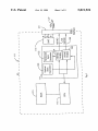
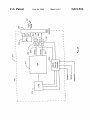
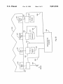
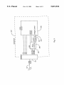
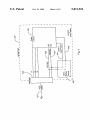
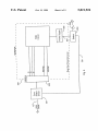
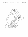
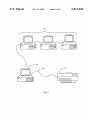
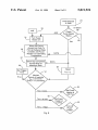
US005821924A
United States Patent
[19]
Kikinis et al.
[54]
[11]
[45]
COMPUTER PERIPHERALS LOW-POWER
CONSUMPTION STANDBY SYSTEM
[75] Inventors: Dan Kikinis, Saratoga; Pascal Dornier,
Sunnyvale, both of Calif.
Patent Number:
Date of Patent:
5,821,924
*Oct. 13, 1998
OTHER PUBLICATIONS
PC Computing, Oct. 1993, p. 297 Nanao USA Corporation.
“One Watt after One Hour in One Year”, NUTEK, Feb.
1993, pp. 1—29.
“Technical Information Datapoint Screensaver”, Datapoint,
[73] Assignee: Elonex I.P. Holdings, Ltd., Great
Britain
Notice:
The term of this patent shall not extend
beyond the expiration date of Pat. No.
5,389,952.
1—4.
“Department of Energy Efficiency”, NUTEK, Jun. 1992, pp.
[21] Appl. No.: 548,662
Oct. 26, 1995
[22] Filed:
1—8.
IBM Technical Disclosure Bulletin, “Increasing Lifetime
and Reliability of CRT Displays”, vol. 34, No. 9; Feb. 1992,
Related US. Application Data
[63]
Jan. 15, 1993, p. 1.
NUTEK Speci?cation 803299/92—93, Dec. 3, 1992, pp. 1—2.
“Installation Instruction ParC 100”, ParaCom, Nov. 5, 1992.
“Environmental Labelling of Display Units”, Presented at
the Third International Scienti?c Conference, Sep. 1992, pp.
pp. 281—283.
Continuation-in-part of Ser. No. 319,256, Oct. 6, 1994,
abandoned, and Ser. No. 175,743, Dec. 30, 1993, Pat. No.
5,489,935, which is a continuation of Ser. No. 940,688, Sep.
4, 1992, Pat. No. 5,321,428, said Ser. No. 319,256, is a
continuation of Ser. No. 141,413, Oct. 22, 1993, Pat. No.
5,389,952, which is a continuation of Ser. No. 984,370, Dec.
“Auto turn—off monitors”, NUTEK, 1992, pp. 1—4.
EDGE: Work—Group Computing Report, Mar. 18, 1991 v2
n43, p. 28(1) Notebook Displays . . . author Phoenix
Technologies Ltd. ( Product Announcement).
(List continued on next page.)
2, 1992, abandoned.
Int. Cl.6 ............................ .. G09G 5/00; 6096 5/12;
H04N 5/63
US. Cl. ........................ .. 345/212; 345/213; 348/730;
395/750.06
Field of Search ................................... .. 345/211—213;
348/730; 395/750, 750.01, 750.03, 750.05,
750.06; 364/707; H04N 5/63
Primary Examiner—Jeffrey Brier
Attorney, Agent, or Firm—Donald R. Boys
[57]
ABSTRACT
A system for loWering the poWer output of a computer
peripheral device connected to a host computer during
periods of inactivity of the host or the peripheral device
senses a poWer management command at the peripheral
References Cited
U.S. PATENT DOCUMENTS
3,453,601
3,588,608
7/1969
Bogert et al. ...................... .. 340/1725
6/1971
Halinski et al. ........................ .. 317/31
(List continued on next page.)
FOREIGN PATENT DOCUMENTS
0 444 997
488384
9/1991
6/1992
European Pat. Off. .
European Pat. Off. .
(List continued on next page.)
device generated at the host computer. Time sensing means
at the host senses inactivity, and gerating circuitry generates
a power-management command. Detection circuitry in the
peripheral device senses the power-management command,
and controls poWer-using circuitry in the peripheral device
in response. In an embodiment applicable to peripherals
having a microprocessor, the system may be incorporated
entirely in softWare at the host and the peripheral device. In
dumb devices, the system requires add-in and/or add-on
apparatus cooperating With softWare.
21 Claims, 9 Drawing Sheets
5,821,924
Page 2
U.S. PATENT DOCUMENTS
3,941,989
3/1976 McLaughlin et a1. ................ .. 235/156
4,338,623
7/1982 Asmus et a1.
4,404,500
9/1983
StoW ..... ..
3-105561
5/1991
Japan .
3-214871
3_238516
9/1991
1O/1991
Japan .
Japan _
358/22
4062614
2/1992
Japan _
. 315/386
4_O95146
3/1992
Japan _
Japan _
4,488,181
12/1984 Heferl .
. 358/220
4096811
3/1992
4,532,457
7/1985 Haferl .
. 315/411
4_107623
4/1992
]apan_
. 358/190
4_107624
4/1992
]apan_
4,553,166
11/1985 Sutton
4,649,373
4,667,289
4,722,005
3/1987 Bland et a1.
5/1987 Yoshida et a1.
1/1988 Ledenbach
. 340/365
. 364/200
. 358/168
4440826
4_188972
4_195091
5/1992
7/1992
7/1992
Japan _
Japan _
Japan _
4,751,502
4,806,784
6/1988 Ishii et a1. ............................. .. 340/709
2/1989 Goda ..................................... .. 307/125
4_20502O
4_245518
7/1992
9/1992
Japan _
Japan _
4,823,121
4/1989 Sakamoto et a1.
. 340/781
4_290388
1O/1992
Japan _
4,922,448
5/1990 Kunieda et al. ..
. 364/900
4344692
12/1992
Japan _
4,980,836
5,021,983
12/1990 Carter et a1.
6/1991 Nguyen et a1.
. 364/483
. 364/707
5_094163
9204394
4/1993
6/1992
Japan _
Rep of Korea _
5,055,940
5,059,961
5,079,666
5,089,754
5,167,024
10/1991 Tomatsuri ..
. 358/444
10/1991 Cheng ................................... .. 340/720
1/1992 Najm ....................................... .. 361/85
. 315/386
. 395/375
2264848
2265232
W0 89/O6012
W0 93/O7558
W0 93/124530
9/1993
9/1993
6/1989
4/1993
6/1993
United Kingdom _
United Kingdom _
WIPO _
WIPO _
WIPO _
2/1992 George
11/1992 Smith et a1.
5,178,152
1/1993
. 128/680
WO 93/15495
8/1993
WIpO _
5,226,122
7/1993 Thayer et a1. .
OZaWa ..... ..
. 395/275
W0 94/O6072
3/1994
WIPO _
5,237,692
8/1993 Raasch et a1. .
395/725
5,245,312
9/1993 Kiuchi et a1. ...................... .. 340/309.4
5,315,311
5/1994
OTHER PUBLICATIONS
Honkala .................................. .. 345/76
5,321,339
6/1994 Hunt ...... ..
. 315/383
PC Week, Feb- 11, 1991 v8 n6, p- 5(1) PS/2 L40sx packs
5,335,168
8/1994 Walker
. 364/707
design novelties . . . author Michael Caton.
5,369,771
11/ 1994 Gene} ------- ~-
- 395/750
Paradise VGA Plus Card User’s Manual, 1988, Appendix D.
573757245 12/1994 Solhlell et al'
- 395/750
IBM Personal System/2198 and Personal Computer BIOS
5’396’635
3/1995 Fung """""" "
' 395/800
Interface Technical Reference by IBM, 1987, pp. 4—59 to
5,423,045
6/1995 Kannan et a1. ....................... .. 395/750
4_61 and 4_121 to 4_125
5,430,881
7/1995
“
574487262
9/1995 Lee et aL
5,457,801
Ikeda ..................................... ..
_ 345/212
10/1995 Aihara ................................... .. 395/750
5,465,366 11/1995 Heineman ............................. ..
5,471,621 11/1995 Ohtsuki ---- -5,481,299 1/1996 Coffey et a1.
.
534813732 1/1996 Shahbazl
'
5,483,464
395/750
1/1996
395/750
395/750
348/123
395/750
Song ..................................... .. 364/492
FOREIGN PATENT DOCUMENTS
I
_
'
_
_
1’
Who s Using Your Electricity When Your Not There ,
NUTEK, PP- 1—8
Vesa Proposal; ‘PoWer Save’ Modez, Video Electronics
Standards Association, 2150 North First Street, Suite 440,
San Jose, CA 95131_202()_
“Monitors Sport Extra Features to Lure Users” InfoWorld
Oct. 5, 1992, IDG Communications, Inc. (p. 397) Copyright
1992 (Abstract).
“Nanao to Introduced LoW—Cost 15—inch WindoWs Moni
0 590 837
57-123598
60-090476
62-106523
62-216018
62-262250
62-276973
63-121365
63-261229
1257893
2-24696
2-053126
2-56620
2-280587
3-091798
4/1994
8/1982
5/1985
5/1987
9/1987
11/1987
12/1987
5/1988
10/1988
10/1989
1/1990
2/1990
2/1990
11/1990
4/1991
European Pat. Off. .
Japan .
Japan .
tor” PC Week vol. 9. No. 42, Oct. 19, 1992, Ziff—Davis
Publishing Company 1992 (p. 30) Copyright (Abstract).
Japan .
“Ecological PCs on the Way: Machine to Feature EPA
Japan .
Approval Stam” PC Week vol. 9, No. 48, Nov. 30, 1992,
Japan .
Ziff—Davis Publishing Company
Japan .
(Abstract).
Japan .
“EiZo Screen Turns on PoWer Saver When Not in Use”
Japan .
Computer Weekly Nov. 12, 1992, Reed Business Publishing
Japan .
Japan .
Japan .
6) Copyright 1992
Group (p. 19) Copyright 1992 (Abstract).
“Into the Station: Memorex Telex Release the 1477 CX
Japan .
Color Display Station and the 1236 Line Printer”
MIDRANGE Systems vol. 5, No. 14 Jul. 21, 1992 Cardinal
Japan .
Business Media Inc.
Japan .
57) Copyright 1992 (Abstract).
U.S. Patent
0a. 13, 1998
<©> wEmO
Km?
/
Sheet 4 0f 9
mmm
5,821,924
U.S. Patent
0a. 13, 1998
Sheet 6 of9
5,821,924
\\Em
lm tlzolzI|l
.9»
m
Dam
\INF
mEmO
,
<®>//
U.S. Patent
0a. 13, 1998
Sheet 7 0f 9
5,821,924
@
.mm
U.S. Patent
0a. 13, 1998
Fig. 7
Sheet 8 of9
5,821,924
U.S. Patent
Oct. 13, 1998
Sheet 9 0f 9
5,821,924
Prlnt
Request
& Data
24
_/
ln Warm
Up
INIT
31
OFF
i
Check
Fuser-Heater
Status
Turn Fuser
Heater On
ON
29
V
Warm Up Period
Accept Any Data To
Print at Reduced Rate
to Buffer until Fuser
Heater is at Operating
Temperature
37
4
DATA
i
Warm-Up Completed
DATA
Accept Data at
39
Maximum Rate
Reset
Set Trigger
tWI = 0
Time
tTRlG
Monitor
Period of Inactivity
tW| = XX (time)
tT RIG = YY (constant)
46
Set Fuser
Heater at
2/3 Pwr
tWl : 5 min.
48
tWI = 30 min.
Set Fuser
Heater at
1/3 Pwr
tWI = 1 Hour
Fig. 8
5,821,924
1
2
COMPUTER PERIPHERALS LOW-POWER
CONSUMPTION STANDBY SYSTEM
than do devices that have electrical heaters. In a typical
Working environment, printers are left on all the time as a
convenience to users and are consequently consuming
poWer in order to keep the fuser-heater at the proper oper
CROSS-REFERENCE TO RELATED
DOCUMENTS
ating temperature and the printer ready to print in response
to instructions from a connected computer, ie a print
This application is a Continuation-In-Part (CIP) of
request. Aprint request sent by a computer is received by the
printer buffer and scheduled for printing, Which typically
copending application Ser. No. 08/319,256, ?led Oct. 6,
1994, noW abandoned, Which is a continuation of application
Ser. No. 08/141,413, ?led Oct. 22, 1993, now US. Pat. No.
5,389,952, Which is a continuation of Ser. No. 07/984,370,
?led Dec. 2, 1992, abandoned. It is also a CIP of copending
application Ser. No. 08/175,743, ?led Dec. 30, 1993, now
US. Pat. No. 5,489,935 Which is a continuation of applica
tion Ser. No. 07/940,688, ?led Sep. 4, 1992, now US. Pat.
No. 5,321,428. All of these prior documents are incorporated
commences When the buffer contains a full page and a “not
10
the main source of noise. If a printer is alloWed to run
15
herein by reference.
FIELD OF THE INVENTION
The present invention is in the ?eld of automatic poWer
busy” message is received from the printer. The fuser-heater
is the principal consumer of poWer in a laser-type printer and
typically a fan for dissipating heat from the fuser-heater is
20
continually and no printing instructions are received, the
fuser-heater Will be kept at a certain set temperature, the fan
Will continue to operate to cool the rest of the printer, and the
printer Will be in a ready state. If the printer is turned off
When not being used, it Will require a certain amount of time
to bring the fuser-heater up to a proper temperature and
begin carrying out instructions from the computer When it is
turned on again in response to a print command. The amount
of time required for a fuser-heater to reach operating tem
perature is dependent on several factors that are unique to
saving methods and devices, and pertains in particular to
reducing poWer consumption by computer peripheral
devices.
each printer. The Wait that is necessarily involved is aWk
BACKGROUND OF THE INVENTION
25
PoWer consumption by computer peripheral devices, such
as printers, display monitors, mass storage devices, and the
like has become, With the expansion of computer
installations, a signi?cant portion of residential and com
mercial poWer requirements. For example, a typical color
in an enclosed area, there may be a heat build-up that must
30
display monitor may consume as much as 50 to 80 percent
Waste, electromagnetic radiation, high-energy radiation and
35
one or more of the connected peripheral devices isn’t
needed. This might be determined by a period of inactivity
on input devices such a modem, mouse and keyboard,
40
circuit or a program that displays moving images (or no
image) to avoid burning the screen phosphors. Activating an
emissions produced by some monitors. Thermal losses from
ditioning equipment. The energy ef?ciency of display moni
45
tors has historically improved mostly as a result of advances
in the electronic circuit components such as the increased
use of integrated circuit (IC) devices. Cathode ray tube
(CRT) technology has improved rather little in terms of
energy efficiency.
50
peripheral device, such as a monitor or printer, or an add-on
device for “dumb” peripherals, to shut doWn or restore some
or all of the device’s electrical poWer circuits. One key to
accomplishing this end is a means of signalling a monitor to
shut doWn to some selected level Without adding to the
sumers of electric poWer. The United States Environmental
signals presently provided to a monitor.
55
SUMMARY OF THE INVENTION
computer manufacturers to design for in neW systems.
LoW-voltage IC’s use less energy, and microprocessor
poWer management techniques alloW a computer to reduce
energy consumption When idling. Until a suitable replace
ment for the CRT or a more ef?cient CRT is developed it Will
input device such as pressing a key or moving a mouse
causes the previous screen image to be restored. This
technique can be extended to reduce peripheral device
poWer consumption by signalling a microcontroller in a
The number of PCs in regular use is groWing rapidly and
has reached a point Where they have become major con
Protection Agency has issued poWer ef?ciency targets for
inactivity of peripheral devices, monitoring of a computer’s
internal bus, and in other Ways. Many computers and display
terminals use such a technique to activate a screen blanking
display monitors. Some people are annoyed by the acoustic
display monitors contribute an additional load on air con
consuming circuits in the display monitor, printers such as
laser printers having fuser heaters, and in other peripheral
devices, When the computer determines that full poWer on
acoustic energy. Only the phosphor emissions are normally
considered useful and then only When actively being
Watched by an observer. The radiation emissions have been
a hotly debated source of concern regarding possible health
risks from long-term exposure. Manufacturers incur consid
erable extra expense to reduce radiation emissions from
be eliminated through climate control equipment to maintain
a successful operation. If the principle heat-producing ele
ment in a laser-type printer, the fuser-heater, could be turned
off for times of non-use, this problem Would be considerably
reduced.
What is needed is a Way to shut doWn high-energy
of the total electrical energy consumed by a personal com
puter (PC). A display monitor dissipates this energy as
visible light emissions from screen phosphors, thermal
Ward and costly in a multi-user environment.
With several computers and one or more printers running
In a preferred embodiment of the invention, in a computer
system having a host computer With a central processing unit
(CPU), a memory, and input apparatus, and having also a
60
connected peripheral device, a poWer management system is
be dif?cult to substantially improve personal computer
energy efficiency.
provided for managing poWer usage by the peripheral
device, comprising a timer for detecting periods of inactivity
As described above, display monitors are not the only
computer peripheral devices Which consume large amounts
at the computer; a signal generator for generating poWer
management commands for the peripheral device; and a
poWer manager circuit in the peripheral device. After pas
sage of a pre-stored time period of inactivity of the host
computer, the timer signals the signal generator to send a
of energy in use. Laser printers are another example. Other 65
peripherals, such as mass storage devices, also consume
electrical energy When not in full use, but to a lessed extent
5,821,924
3
4
power management command to the peripheral device, and
distinct signals to a monitor to signal the monitor to adjust
the poWer manager circuit in the peripheral device causes
the peripheral device to assume a reduced-poWer state other
than off in response to the poWer management command.
to as many as three states. In an embodiment of the
Speci?c embodiments manage poWer for such as display
monitors and printers having fuser heaters, as these devices
interrupting one or the other or both HSYNC and VSYNC
invention, the states are selected levels of monitor poWer
management (MPM). The signal to the monitor is based on
signals. In the embodiment shoWn in FIG. 1 a PC 111
comprises a Basic Input Output System (BIOS) 113 and a
Video Graphics Adapter (VGA) 117. The invention Will
Work equally Well With other video adapters, as virtually all
such adapters employ HSYNC and VSYNC signals. In some
other adapters, equivalent means of interrupting the HSYNC
and VSYNC signals Would be used.
use excess poWer by virtue of heating apparatus. In some
embodiments reduced-poWer states are delayed after a com
mand.
A computer is provided comprising a central processing
unit (CPU), a memory connected to the CPU for storing data
and instruction routines, input apparatus coupled to the CPU
for a user to provide input to the computer, a timer for
detecting periods of inactivity of the computer, and a signal
generator adapted for sending a poWer management com
mand to a peripheral device. In this embodiment the timer,
in response to passage of a pre-stored period of inactivity of
the computer, signals the signal generator to send the poWer
15
management command to the peripheral device to assume a
ments instructions for implementing MPM might be embed
ded in operating system (OS) device driver routines or
Terminate and Stay Resident (TSR) programs.
The MPM instructions monitor CPU 115 interrupts for
input devices (not shoWn) such as the timer, keyboard and
reduced-poWer state other than off. In one alternative signals
are sent to a peripheral device by disabling one or more
signals typically sent. The pattern of disabled signals pro
vides a unique command.
Control routines for poWer management in embodiments
of the present invention may reside in any one of several
BIOS 113 includes instructions for MPM, Which can
cause a central processing unit (CPU) 115 to change the state
of sync-enable controls in VGA 117. In alternative embodi
25
serial communication ports. MPM instructions advance a
time-out counter on each timer interrupt and reset the count
to an initial value on each monitored interrupt. The initial
value of the MPM time-out counter may be ?xed or adjust
able. When the MPM time-out counter reaches a preset
over?oW value, due to cessation of monitored interrupts,
locations. Such control routines may be a part of a BIOS or
instructions are executed that change the state of HSYNC
Enable 124 and VSYNC Enable 126 control to disable
of an operating system, for example.
In some embodiments, apparatus for enabling poWer
management is provided as an add-in (expansion card) or by
output of horiZontal synchroniZation signals (HSYNC) 123,
produced by horiZontal sync generator 122, and/or vertical
add-on apparatus. In many embodiments several different
synchroniZation signals (VSYNC) 125, produced by vertical
signals may be sent, corresponding to different activity
sync generator 120, or both. A subsequent monitored inter
rupt causes execution of instructions that change the state of
HSYNC Enable 124 and VSYNC Enable 126 control cir
cuits to enable output of HSYNC 123 and VSYNC 125
signals from VGA 117.
criteria, and different poWer levels are provided in response
to the different commands.
BRIEF DESCRIPTION OF THE DRAWINGS
FIG. 1 is a largely schematic representation of a PC
according to an embodiment of the present invention.
FIG. 2A is a largely schematic representation of a PC
enhanced by an add-on device according to an alternative
embodiment of the present invention.
FIG. 2B is a largely schematic representation of a PC
enhanced by an add-in device according to another alterna
tive embodiment.
FIG. 3 is a largely schematic representation of a
microcontroller-based video monitor according to an
embodiment of the present invention.
FIG. 4 is a largely schematic representation of a “dumb”
monitor equipped With an add-in device according to an
alternative embodiment of the present invention.
FIG. 5 is a largely schematic representation of an add-on
device for controlling AC primary poWer to a monitor
according to another alternative embodiment of the present
invention.
FIG. 6 is a vieW of a laser-type printer as used With the
35
In the case of a VGA controller, the enable/disable capa
bility is through Writing by the CPU into register 3C2 of the
controller, Wherein bits six and 7 are reserved for horiZontal
retrace polarity and vertical retrace polarity respectfully.
HSYNC and VSYNC signals 123 and 125 are brought to
interface 121 along With other signals, such as R, G, and B
signals from D/A/converter 119. The signals are transmitted
to a monitor on VGA cable 127 as is knoWn in the art. The
45
Reference, published by IBM in 1987.
In an alternative embodiment, shoWn in FIG. 2A, useful
for re?tting existing computers, a current art PC 211 having
a CPU 215 is enhanced by installation of a sWitch 231,
Which connects betWeen a VGA217 VSYNC output 225 and
VSYNC input 226 to a video interface 221. In a color
55
present invention.
FIG. 7 is a draWing of a laser-type printer operated
causes instructions to be executed Which change the state of
according to the present invention on a netWork With several
FIG. 8 is a How chart of the printing process according to
the present invention.
FIG. 1 shoWs the functional elements of a preferred
embodiment of the present invention capable of providing 3
computer, R,G, and B signals are brought to interface 221
from DAC 219. An add-in time-out controller 229 compris
ing MPM instructions monitors input device activity as
described above for FIG. 1. Time-out of all input devices
program-controlled sWitch 231, blocking VSYNC input 225
computers.
DESCRIPTION OF THE PREFERRED
EMBODIMENTS
pin-out for the signals on a VGA cable is Well-known, and
is shoWn in IBM Personal System/2, Model 80 Technical
65
to video interface 221. Resumption of monitored interrupts
causes sWitch 231 to close, returning the VSYNC signals to
line 226. A second sWitch 232 may be used in the HSYNC
line to interrupt the HSYNC signals to line 224, and, in this
embodiment, the add-in time-out controller controls both
sWitches. In yet another alternative, one sWitch may be used
to interrupt both HSYNC and VSYNC signals.
The functional blocks presented in FIG. 2A are an internal
solution to an add-in hardWare/softWare embodiment, and
5,821,924
5
6
the blocks are not intended to be taken literally as hardware
devices and interfaces. It Will be apparent to one With skill
in the art that there are many equivalent Ways the functional
Without a microcontroller. A sync detect circuit 451 com
pares pulse intervals for HSYNC 435 and VSYNC 437
against time-constants of adequate duration to alloW for
brief interruptions of sync pulses. Loss of HSYNC 435
blocks might be accomplished. The keyboard, mouse, and
modem inputs are monitored by the add-in controller, and
pulses or VSYNC 437 pulses for periods longer than the
associated time-constants causes sync detector circuit 451 to
are made available as Well to the CPU in the typical manner.
FIG. 2B shoWs an external solution for a hardWare/
softWare embodiment. In this solution an add-on time-out
controller 259 is external to computer system 233, and each
port that supports an input device and the video output port
change Level-1 signal line 441 or Level-2 signal line 443
voltage to its active state as described for FIG. 3 and With the
10
is ?tted With an interface device connected to the add-on
time-out controller. For example, interface 243 at COM port
241 used for a modem 245 monitors modem activity and
reports to controller 259 on line 244. Interface 249 at
keyboard port 247 monitors keyboard 251 activity and
15
external enclosure having pass-through connections, inserts
into VGA cable 127. Sync detect circuit 551 monitors video
signals on VGA cable 127 and compares the SYNC interval
reports to controller 259 on line 250. Interface 255 at pointer
port 253 monitors pointer 257 activity (mouse, joystick,
for one or the other of VSYNC and HSYNC to a time
constant in a manner similar to that described for FIG. 4
trackball), and reports to controller 259 on line 256.
In this embodiment controller 259 accomplishes the timer
functions and outputs signals on line 238 to interface device
237 at video port 235. Line 239 goes to the monitor. Device
above. Loss of the monitored SYNC signal in VGA cable
127 for an interval longer than the time-constant causes sync
detect circuit 551 to change the voltage on poWer-control
237 interrupts HSYNC and VSYNC signals according to the
over?oW states of add-on controller 259.
Acolor video monitor 347 according to an embodiment of
the present invention is shoWn in FIG. 3. Monitor 347
comprises an interface 333, a microcontroller 339 having
MPM instructions according to the present invention and a
same results. Similarly, resumption of HSYNC 435 and
VSYNC 437 pulses reactivates monitor 447 as described for
FIG. 3 above.
FIG. 5 shoWs another alternative embodiment of the
present invention suitable for add-on use With a monitor 547
having an interface 533. A sync detect circuit 551, in an
line 561 to its active level, Which in turn causes an
electronically-controlled sWitch 553 to open. Electronically
25
controlled sWitch 553 controls AC primary poWer from an
electrical cord 559 to a receptacle for monitor 547 poWer
supply cord 557. When electronically-controlled sWitch 553
opens, AC poWer to a DC poWer supply 555 is lost, thus
video circuit (VC) 345 having voltage control circuitry.
causing total shutdoWn of monitor 547. Resumption of
From interface 333 HSYNC pulses 335 and VSYNC pulses
SYNC signals in VGA cable 127 video signal causes sync
detect circuit 551 to change poWer-control line 561 to its
337 go to microcontroller 339. Microcontroller 339 moni
tors the HSYNC signal 335 and VSYNC signal 337. The
quiescent state, thus causing electronically-controlled
MPM instructions described above count the number of
sWitch 553 to close, Which restores AC poWer input to DC
HSYNC pulses occurring betWeen each pair of VSYNC
pulses. Zero HSYNC pulses counted causes the MPM
instructions in microcontroller 339 to change the voltage on
Level-2 signal line 343. Similarly, an interval count of
HSYNC 335 pulses greatly in excess of the maximum video
scan rate for monitor 347, indicating a loss of VSYNC 337,
causes microcontroller 339 to change the voltage on Level-1
signal line 341. Resumption of HSYNC 335 to VSYNC 337
poWer supply 555 reactivating monitor 547.
35
described, such as MPM instructions implemented in an OS
device driver or TSR routines instead of the BIOS, single
level MPM instead of tWo-level MPM and an external video
pulse interval counts to a range from the minimum to the
maximum scan rate causes MPM instructions in microcon
troller 339 to restore quiescent voltage levels to Level-1
signal line 341 and Level-2 signal line 343.
It Will be apparent to one With skill in the art that there are
many changes that might be made in the embodiments
describing poWer-management of display monitors and the
like Without departing from the spirit and scope of the
invention. Some of these alternatives have already been
45
When video circuit 345 senses an active voltage level on
Level-1 signal line 341, it cuts off poWer to all circuits in
monitor 347 except microcontroller 339, any poWer neces
sary to interface 333, and video circuit 345 poWer-control
circuits (not shoWn). In this level 1 standby mode, poWer
consumption of monitor 347 is reduced by more than 90
percent. If monitor 347 remains in level 1 standby for more
than a feW seconds, full Warm-up time is required to
reactivate it. An active voltage level on Level-2 signal line
monitor poWer control device. Other methods of signalling
MPM state changes to a monitor might include time-based
coded sequences of frequency changes in HSYNC or
VSYNC, coded values in the color signals, or no color signal
for an extended period. Alternative embodiments of MPM
routines might alloW an operator to control MPM operation
through command steps, such as menus, dialog boxes or
command lines. Such controls might include shutting doWn
monitor poWer at Will by pressing a “hot key”, typing a
command line or other program interface step. Other fea
5 seconds or less. Reactivation of monitor 347 occurs When
tures might alloW the operator to change the idle time
required to trigger MPM and toggle MPM monitoring on or
off. Alternative MPM routines might also require an operator
to type a passWord before enabling the transmission of
normal video signals to the video monitor. Alternative
devices for both built-in and post-manufacture modi?cation
to implement monitor poWer control might be devised.
Embodiments of the present invention for monochromatic
voltage on Level-1 signal line 341 and Level-2 signal line
343 returns to the quiescent state alloWing video circuit 345
templated.
343 causes video circuit 345 to cut off poWer to all circuits 55
except those described above plus the CRT cathode heater.
In level 2 standby mode monitor 347 poWer consumption is
reduced by 80 to 90 percent. Because the CRT is kept hot,
reactivating monitor 347 from level 2 standby requires about
and grey-scale video adapters and monitors are also con
to activate poWer to all circuits of monitor 347.
As described above, display monitors are not the only
FIG. 4 shoWs an alternative embodiment of the present
computer peripheral devices Which consume large amounts
invention in a monitor 447 With video circuits functionally 65 of energy While is a resting condition. Laser printers, and
similar to those described for the monitor shoWn in FIG. 3,
other printers that use fusing processing requiring heat are
another example.
including an interface 433 and a video circuit 445, but
5,821,924
8
7
performs this function automatically. In a preferred mode of
operation the reduced data acceptance rate is set to be equal
FIG. 6 is an isometric drawing of a laser-type printer 1013
operable according to the present invention, and Which
contains a fuser-heater 1015, a drum 1016, a fan 1018, a
buffer 1020, a controller 1022, and a cable connection 1023
that joins the printer to a host computer or a to a netWork.
to or smaller than the buffer siZe divided by the Warm-up
time. In some embodiments the control routines can further
be manipulated to manually turn the fuser-heater on or off at
any time.
Fuser-heater 1015 is responsible for heating the toner
applied to drum 1016 after an image has been Written to the
FIG. 8 is a flow diagram illustrating the operation of the
present invention to control laser-type printer functions and
drum to fuse the toner to the paper. Instructions sent by a
computer What is Written, and the entire process is managed
by control routines. Fan 1018 (if used) in the printer is
poWered on at start up and is usually controlled by a
heat-sensing mechanism that reacts to internal temperature
and runs in reaction to cool mechanical and electronic
elements of the printer. The majority of printers have a
memory buffer that electronically stores composed pages
transmitted by the control routines and sends the data to the
processing unit of the printer as the printer is ready to accept
it. When the buffer has emptied its contents to the printer and
all instructions from the computer have been carried out, the
printer Waits for further input and maintains all of its
thereby save poWer and decrease noise.
10
An INIT signal (point 1026) is received from a host
system When the system starts up, such as after an inten
tional doWntime. INIT turns on fuser-heater 1015 at point
1031 as a consequence of turning on the printer itself. The
INIT signal or similar signal is also received When a
15
laser-type printer is turned on directly. After start-up, the
system responds to print requests from the server 1027 or
any one of the computers 1025 on the netWork (FIG. 7). The
system receives a print request at point 1024 and determines
Whether the fuser-heater is on, off, or in a Warm-up mode
(point 1029).
components in a state of readiness. Actual operation can
vary from printer to printer according to the type and speed
If the fuser-heater is on and at operating temperature When
of the printer and the siZe of the printer buffer. It is not the
intent of the present description to present a detailed descrip
tion of laser-type printing, but rather to present an eXample
of a relatively common printing function and demonstrate its
functional components in the context of the present inven
tion.
a print request is received, data is accepted by the buffer at
maXimum rate (1037). The rate for a particular printer buffer
25
is unique to each laser-type printer.
The printer fuser-heater is managed by monitoring the
time betWeen print requests (1041). This time is designated
FIG. 7 demonstrates laser-type printer 1013 operating Within
tWI, for time Without input, and is measured by a timer in the
control circuitry. The timer is reset to Zero (1043) each time
a print request is received and the printer is determined to be
a netWorked environment of other computers 1025 and
possibly other printers and With a netWork server computer
1027. The present invention provides a means to keep the
initialiZed and at operating temperature. A trigger time,
TTRIG, is set (1039) for a maXimum period betWeen print
requests, and the fuser-heater is shut off (1045) When
The embodiment of the present invention as shoWn in
tW,=tTR,G. In some embodiments the trigger time may be set
printer operating and prepared to print but to save poWer by
turning off the fuser-heater portion of the laser-type printer.
35
In response to a reduction in heat created by turning off the
fuser-heater, the fan Will shut doWn and run only
infrequently, if at all, in response to ambient heat from other
sources.
The connection to a computer or computers is never
broken. The turning off of the fuser-heater signi?cantly
lessens poWer consumption and heat dissipation require
ments.
Control routines that are a part of the invention can be
installed on any computer that uses a printer that uses a 45
fuser-heater or can be installed solely on netWork server,
If, When a print request is received, the fuser-heater is in
a Warm-up mode (1035), data from a print request is
accepted at a sloWer rate than the maXimum data transfer
rate available. Data is accepted at the maXimum rate after the
fuser-heater is at operating temperature. If When a print
request is received the fuser-heater is off, the control system
turns it on (1031), putting the fuser-heater in Warm-up mode,
and the printer buffer accepts data more sloWly until the
fuser-heater is at operating temperature. The amount of time
it takes for the fuser-heater to Warm up is dependent upon the
particular printer, and can vary. Additional contributing
factors to the length of Warm-up time include the difference
betWeen a printer being poWered on after an intentional
doWntime, in Which the length of time it takes to Warm up
is naturally greater, and the case When a print request has
such as server 1027 in FIG. 7, or may be installed preferably
in the printer. The system of the invention comprises a
means of turning off fuser-heater 1015 (FIG. 6) in laser-type
printer 1013 after a set amount of time has passed Without
any input from the netWork server or from the connected
computer or computers, and to turn it back on again When
the connection is initialiZed (such as When a computer on the
netWork is turned on) or a print request is sent from an
attached netWork server or single computer. The printer
stays on all the time, and only the fuser-heater element is
turned off.
When the fuser-heater is turned back on after being
poWered doWn, it requires a certain amount of time to reach
in the softWare and not accessible as a variable to a user.
been handled only moments before, requiring only a short
Warm-up.
In an alternative, and someWhat more sophisticated
embodiment of the invention, there is more than one trigger
55
time, and the fuser-heater is only partially shut doWn in some
instances. For example, the control routines may be Written
and hardWare included in a printer, so the fuser-heater, after
a ?rst period of 5 minutes, Would be reduced to 2/3 poWer. If
no print request is received after 30 minutes, the poWer
Would be reduced to 1/3, and if no request is received after 1
hour, the poWer Would be shut off.
the correct operating temperature. During this time, the
printer buffer is fully active and still accepts input but does
so more sloWly than usual until the fuser-heater is at
This embodiment addresses the possible reasons for no
operating temperature. This sloWer data acceptance rate
avoids softWare timeouts, such as might occur When printing
from DOS. Auser Will seldom notice sloWer operation and
print requests. The 5 minute trigger addresses the ongoing
Will not be aWare that an element in the printer has been
turned off or conversely, turned back on again. The system
65
situation that assumes that the users have only periodic need
for the printer, and alloWs for rapid Warm up When a neW
request is received. The 30 minute trigger anticipates situ
ations like lunch time and shift change, and still alloWs for
5,821,924
10
a shorter Warm up than a complete shut doWn. The one hour
erator comprises the CPU signaling an adapter to disable one
trigger anticipates everyone has gone home for the day or the
Weekend, and shuts off the poWer completely.
In this embodiment, the times may be adjusted empiri
cally to provide the minimum poWer usage for the demand
pattern of a particular organiZation, and in other embodi
of several signals provided by the adapter for communicat
ing With the peripheral device.
6. A computer as in claim 5 Wherein the control routines
are provided in a basic input output system (BIOS) in a
programmable read-only memory.
7. A computer as in claim 4 Wherein the timer and the
signal generator are parts of an add-in time-out controller
ments more or feWer trigger times might be useful.
It Will be apparent to one With skill in the art that there are
a number of changes that may be made to the embodiments
of the invention described herein Without departing from the
spirit and scope of the invention. One of these is the fact that
the invention is not limited to any particular computer,
10
pointer device, and the timer and the signal generator are
device. Computers or printer With fuser-heaters of any
manufacture can be used providing control routines are 15
Written in the languages that the computers and printers
parts of an add-on time-out controller, Wherein the timer is
connected to sensing devices interfaced at input ports for the
input apparatus, and the signal generator is interfaced to a
port providing signals for communicating With the periph
require. The present invention can also be used to control
several printers that are connected together into a netWork,
and still alloW manual operation of any one of the printers.
eral device.
9. A computer peripheral device having a port for signals
for communicating With a host computer, comprising:
a receiver adapted for receiving a poWer-management
The invention is broadly applicable to any system using
printers that have fuser-heaters, as Well as to display
command; and
monitors, mass storage devices, and other peripheral
a poWer manager circuit;
Wherein the receiver sends a command to the poWer
devices.. It is seen, then, that there are many alterations that
25
manager circuit on receiving the poWer-management
command, and the poWer manager circuit reduces
poWer to poWer-using circuitry in the peripheral device
to an intermediate level other than off in response to the
command from the receiver.
10. A computer peripheral device as in claim 9 Wherein
central processing unit (CPU), a memory, and input
apparatus, and having also a connected peripheral device, a
poWer management system for managing poWer usage by
the receiver is adapted for receiving and discriminating
among different poWer-management commands.
11. A computer peripheral device as in claim 10 Wherein
the peripheral device, comprising:
a timer for detecting periods of inactivity at the computer;
a signal generator for generating power-management
commands for the peripheral device; and
a poWer manager circuit in the peripheral device;
Wherein, after passage of a pre-stored time period of
8. A computer as in claim 4 Wherein the input apparatus
comprises one or more of a keyboard, a modem, and a
netWork server, printer, display monitor, or other peripheral
may be made Without departing from the spirit and scope of
the invention.
What is claimed is:
1. In a computer system having a host computer With a
adaptable to an eXisting computer by connecting to eXisting
signal lines of the computer.
35
inactivity of the host computer, the timer signals the
the poWer manager reduces poWer to different reduced
poWer levels in response to the different poWer-management
commands.
12. Amethod for saving poWer in operation of a computer
system Wherein a host computer sends signals to a peripheral
device, comprising steps of:
(a) sensing periods of inactivity of the host computer;
signal generator to send a poWer management com
mand to the peripheral device, and the poWer manager
circuit in the peripheral device causes the peripheral
(b) sending a poWer-management command to the periph
device to assume a reduced-poWer state other than off
host computer;
(c) detecting the poWer-management command at the
in response to the poWer management command.
2. ApoWer management system as in claim 1 Wherein the
peripheral device is one of a printer having a fuser heater and
a display monitor.
3. ApoWer-management system as in claim 1 Wherein the
peripheral device has a ?lament heater, and poWer is reduced
but not suspended to the ?lament heater in one of the
eral device in response to a period of inactivity of the
45
eral device from the detection circuitry that a poWer
management command is received; and
(e) reducing poWer to poWer-using circuitry in the periph
eral device to a level other than off by the poWer
reduced-poWer states.
4. A computer comprising:
a central processing unit (CPU);
management circuitry in response to the signal from the
detection circuitry.
13. The method of claim 12 Wherein in the reducing
a memory connected to the CPU for storing data and
poWer step, poWer is reduced but not suspended to a ?lament
instruction routines;
input apparatus coupled to the CPU for a user to provide
peripheral device by detection circuitry;
(d) signaling poWer-management circuitry in the periph
55
heater in the display monitor.
14. The method of claim 12 Wherein in the reducing
input to the computer;
a timer for detecting periods of inactivity of the computer;
poWer step poWer is suspended to a ?lament heater in the
and
a signal generator adapted for sending a poWer manage
ment command to a peripheral device;
Wherein the timer, in response to passage of a pre-stored
poWer-management commands are sent according to differ
peripheral device.
15. The method of claim 12 Wherein, in step (b), different
ent periods of inactivity in step (a).
16. The method of claim 15 Wherein alternative distinct
reduced-poWer states are provided according to the different
period of inactivity of the computer, signals the signal
periods of inactivity.
generator to send the poWer management command to
the peripheral device to assume a reduced-poWer state
other than off.
5. A computer as in claim 4 Wherein the timer comprises
control routines eXecuted by the CPU, and the signal gen
65
17. In a computer having circuitry providing signals to a
peripheral device, a method for signaling the peripheral
device to assume alternative poWer-using states, comprising
steps of:
5,821,924
11
(a) detecting different periods of inactivity of the com
puter; and
(b) sending power management commands to the periph
eral device to assume alternative power states in
response to detecting the different periods of inactivity
of the computer.
18. A method for directing assumption of an alternative
poWer-using state in a computer peripheral device, compris
ing steps of:
detecting a poWer-management command sent to the
peripheral device from a host computer; and
signaling poWer-management circuitry in the peripheral
device to assume an intermediate poWer level other
than off in response to the poWer-management com
mand.
19. The method of claim 18 Wherein different poWer
management commands are detected and alternative differ
ent poWer levels are assumed in response.
20. A computer peripheral device comprising:
a detector adapted for detecting a poWer management
command conveyed to said peripheral device by a host
computer; and
12
poWer level control circuitry responsive to said detector
for managing poWer-using circuitry in said peripheral
device;
Wherein said detector detects said poWer management
command, and said poWer level control circuitry pro
vides in response tWo reduced-poWer states for said
peripheral device, one of the reduced-poWer states
delayed for a predetermined period of time after the
initiation of the other reduced-poWer state.
21. A computer peripheral device having a cathode ?la
ment and a ?lament heater, comprising:
a detector adapted for detecting a poWer management
command conveyed to said peripheral device by a host
computer; and
poWer level control circuitry responsive to said detector
for managing poWer-using circuitry in said peripheral
device;
Wherein said detector detects said poWer management
command, and said poWer level control circuitry pro
vides in response an intermediate reduced-poWer state
Wherein the ?lament heater is on.