1
HD DIGITAL VIDEOCASSETTE RECORDER
HDW-F500
PARALLEL INTERFACE KIT
BKDW-509
HD-525 DOWNCONVERTER BOARD
HKDV-501A
HD LINE CONVERTER BOARD
HKDV-502
HD DIGITAL VIDEO CONTROLLER
HKDV-503
SDTI BOARD
HKDV-506A
HD PULL DOWN BOARD
HKDV-507
OPERATION MANUAL [ English ]
1st Edition
Serial No. 10101 and Higher
WARNING
To prevent fire or shock hazard, do not
expose the unit to rain or moisture.
To avoid electrical shock, do not open the
cabinet. Refer servicing to qualified
personnel only.
For the customers in U.S.A.
This equipment has been tested and found to comply with
the limits for a Class A digital device, pursuant to Part 15 of
the FCC Rules. These limits are designed to provide
reasonable protection against harmful interference when the
equipment is operated in a commercial environment. This
equipment generates, uses, and can radiate radio
frequency energy and, if not installed and used in
accordance with the instruction manual, may cause harmful
interference to radio communications. Operation of this
equipment in a residential area is likely to cause harmful
interference in which case the user will be required to
correct the interference at his own expense.
You are cautioned that any changes or modifications not
expressly approved in this manual could void your authority
to operate this equipment.
This device requires shielded interface cable to comply with
FCC emission limits.
This symbol is intended to alert the
user to the presence of important
operating and maintenance (servicing)
instructions in the literature
accompanying the appliance.
WARNING: Using this unit at a voltage other than 120 V
may require the use of a different line cord or attachment
plug, or both. To reduce the risk of fire or electric shock,
refer servicing to qualified service personnel.
Table of Contents
1-1 Features ............................................................................................ 1-1
1-1-1 Features of the HDW-F500 .................................................... 1-1
1-1-2 Features of the Control Panel ................................................. 1-3
1-2 Optional Accessories ....................................................................... 1-5
Chapter 2
Locations and Functions
of Parts and Controls
2-1 Control Panel ................................................................................... 2-1
2-1-1 Upper Control Panel ............................................................... 2-2
2-1-2 Lower Control Panel (Menu Operations Section) .................. 2-5
2-1-3 Lower Control Panel (Editing Operations Section) ................ 2-7
2-1-4 Lower Control Panel (Tape Transport Operations Section) ... 2-9
2-1-5 Lower Control Panel (Search Operations Section) ............... 2-11
2-2 System Set-Up Panel ..................................................................... 2-13
2-3 Connector Panel ............................................................................ 2-14
Chapter 3
Setting Up the VTR
Chapter 4
Menu Settings
(Continued)
3-1 Connecting External Equipment ................................................... 3-1
3-1-1 Making Digital Connections ................................................... 3-1
3-1-2 Making HD Analog Connections ........................................... 3-2
3-1-3 Making NTSC Digital Connections ....................................... 3-3
3-1-4 Cascade connection ................................................................ 3-4
3-2 Reference Signals for Video Output and Servo System............... 3-5
3-2-1 Reference Signals for Output Video ....................................... 3-5
3-2-2 Reference Signals Connections .............................................. 3-6
3-3 Handling Cassettes .......................................................................... 3-8
3-3-1 Recommended Cassettes ........................................................ 3-8
3-3-2 Inserting and Ejecting Cassettes ............................................. 3-8
3-3-3 Preventing Accidental Erasure ............................................... 3-9
4-1 Registering and Storing Menu Settings......................................... 4-1
4-1-1 Menu Configuration ............................................................... 4-1
4-1-2 Changing Menu Settings ........................................................ 4-2
4-1-3 Registering Items to the PF1/2 Menus ................................... 4-3
4-1-4 VTR Memory Bank Function ................................................. 4-4
4-1-5 Memory Card Function .......................................................... 4-6
4-1-6 Adding Titles to the Data ...................................................... 4-11
4-1-7 Details on VTR Memory Bank and Memory Card
Functions .............................................................................. 4-12
4-1-8 Memory Card Data Compatibility ........................................ 4-13
4-2 HOME Menu ................................................................................. 4-14
4-2-1 Selecting the Output Signals(PB/EE) ................................... 4-16
4-2-2 Record Inhibit Mode (REC INH) ......................................... 4-16
4-2-3 Selecting the Edit Mode and Edit Channel
(ASSEMBLE or INS CUE) ................................................. 4-17
4-2-4 Preread Settings (PRE READ) ............................................. 4-17
4-2-5 Still-Picture Output (FREEZE) ............................................ 4-17
4-2-6 Selecting the Capstan Servo Lock Mode (CAP LOCK) ...... 4-18
4-2-7 Setting the Preroll Time (PREROLL TIME) ....................... 4-18
4-2-8 Selecting DMC Playback (DMC) ......................................... 4-19
4-2-9 Recalling Edit Points (LAST EDIT) .................................... 4-19
Table of Contents
1
Table of Contents
Chapter 1
Overview
Table of Contents
Table of Contents
Chapter 4
Menu Settings
2
Table of Contents
4-3 TC Menu ........................................................................................ 4-20
4-3-1 Setting the Time Data (TIMER SEL/RESET/SET/HOLD) 4-21
4-3-2 Setting the Time Code Reader (TCR SEL) .......................... 4-24
4-3-3 Setting the Time Code Generator (TCG SOURCE/MODE) 4-25
4-3-4 Selecting the Time Code Running Mode (RUN MODE) ..... 4-25
4-3-5 Selecting the Drop Frame Mode (DF/NDF) ......................... 4-25
4-3-6 Inserting VITC input source (VITC) .................................... 4-26
4-3-7 Selecting CTL Display Mode (TAPE TIMER) .................... 4-26
4-3-8 Presetting Pull Down Time Code (PDPSET MENU)
(when HKDV-507 is installed) ............................................ 4-26
4-3-9 Conversion of Time Code When Playing Back in the 25F Mode
(TC CONV) .......................................................................... 4-27
4-3-10 Displaying the Pull Down Time Code
(when HKDV-507 is installed) ............................................ 4-28
4-3-11 Superimposition of Character Information (PD CHARA/
CHARA SUPER/H-POS/V-POS) ....................................... 4-28
4-3-12 Setting the VITC Insertion Line (VITC POS-1/POS-2) ..... 4-31
4-4 CUE Menu ..................................................................................... 4-32
4-4-1 Selecting a Multi-Cue Mode ................................................. 4-33
4-4-2 Registering Cue Points ......................................................... 4-33
4-4-3 Erasing Cue Point Data ......................................................... 4-35
4-4-4 Prerolling to a Cue Point ...................................................... 4-36
4-4-5 Changing a Cue Point Into an Edit Point .............................. 4-37
4-4-6 Backspace Editing ................................................................ 4-37
4-5 PF1 Menu (Factory Settings) ....................................................... 4-38
4-5-1 Selecting the Input Video Signal (VIDEO IN) ..................... 4-39
4-5-2 Selecting the Reference Signal (SERVO REF) .................... 4-39
4-5-3 Adjusting the Output Video Signal (MASTER LEVEL to
FINE) ................................................................................... 4-39
4-6 PF2 Menu (Factory Settings) ....................................................... 4-42
4-6-1 Selecting the Audio Input Signal (A-IN CH-1~CH4) .......... 4-43
4-6-2 Setting Emphasis (EMPHASIS) ........................................... 4-43
4-6-3 Selecting the Monitor Output Signal (MON-L SEL/MON-R
SEL) ..................................................................................... 4-43
4-7 SET UP Menu ................................................................................ 4-44
4-7-1 VTR SETUP Menu ............................................................... 4-46
4-7-2 PANEL SETUP Menu .......................................................... 4-48
5-1 Preparing for Recording................................................................. 5-1
5-1-1 Setting Switches and Menus ................................................... 5-1
5-1-2 Selecting Audio Signals .......................................................... 5-2
5-1-3 Adjusting the Audio Recording Level .................................... 5-3
5-1-4 Simultaneously Monitoring Playback of Video and Audio
Signals Being Recorded ......................................................... 5-4
5-1-5 Recording Analog Audio ........................................................ 5-4
5-2 Recording ......................................................................................... 5-5
5-3 Preparing for Playback................................................................... 5-6
5-3-1 Setting Switches and Menus ................................................... 5-6
5-3-2 Adjusting the Audio Playback Level ...................................... 5-6
5-3-3 Selecting the HD-SD Conversion Mode
(when HKDV-501A is installed) ........................................... 5-7
5-3-4 Selecting the Conversion Mode of the Effective Scanning Line
Number (when HKDV-502 is installed) ................................ 5-7
5-3-5 Improving the Vertical Resolution during Slow-Motion
Playback (when HKDV-502 is installed)............................... 5-9
5-4 Playback ......................................................................................... 5-10
5-4-1 Normal-Speed Playback ....................................................... 5-10
5-4-2 Variable Speed Playback ...................................................... 5-10
5-4-3 Capstan Override Playback .................................................. 5-13
5-4-4 DMC Playback ..................................................................... 5-13
Chapter 6
Editing
6-1 Basic Automatic Editing ................................................................. 6-1
6-1-1 Overview of Automatic Editing ............................................. 6-1
Chapter 6 Editing ............................................................................. 6-1
6-1-2 Setting Switches and Menus ................................................... 6-2
6-1-3 Selecting the Edit Mode ......................................................... 6-3
6-1-4 Setting Edit Points .................................................................. 6-3
6-1-5 Confirming Edit Points ........................................................... 6-8
6-1-6 Cuing Up and Prerolling ......................................................... 6-8
6-1-7 Previewing .............................................................................. 6-9
6-1-8 Modifying Edit Points .......................................................... 6-10
6-1-9 Performing Automatic Editing ............................................. 6-12
6-2 Advanced Automatic Editing ....................................................... 6-15
6-2-1 Performing DMC Editing ..................................................... 6-15
6-2-2 Animation Editing ................................................................ 6-17
6-2-3 Performing Preread Editing .................................................. 6-18
6-3 Manual Editing ........................................................................... 6-A19
Table of Contents
3
Table of Contents
Chapter 5
Recording/Playback
Table of Contents
Table of Contents
Appendix
4
Table of Contents
Maintenance .......................................................................................... A-1
Head Cleaning ................................................................................. A-1
Moisture Condensation ................................................................... A-1
Specifications ......................................................................................... A-2
Operation Information Display ........................................................... A-6
Error Messages and Warning Messages ............................................ A-8
Error Messages ................................................................................ A-8
Warning Messages ........................................................................ A-10
Error Log Menu ............................................................................. A-11
Glossary ............................................................................................... A-13
Menu List ............................................................................................ A-15
Items Related to the Hours Meter (H01~) ..................................... A-15
Items Related to VTR Operations (001~) ..................................... A-16
Items Related to Operation Panels (101~) .................................... A-20
Items Related to Remote Interface (201~) .................................... A-23
Items Related to Editing (301~) .................................................... A-24
Items Related to Prerolling (401~) ................................................ A-27
Items Related to Recording Protection (501~) .............................. A-28
Items Related to the Time Code (601~) ........................................ A-29
Items Related to the Video Control (701~) ................................... A-34
Items Related to the Audio Control (801~) ................................... A-39
Items Related to Digital Processing (901~) .................................. A-41
Items Related to the Pull Down Control (A01~) ........................... A-43
Other Items (T01~) ........................................................................ A-44
Index ........................................................................................................ I-1
Table of Functions (Factory Default Settings) ......................... Last page
1-1 Features
The HDW-F500 is a HD digital videocassette recorder
using the HDcam format. Comparable to a
conventional digital Betacam in size, weight, and easeof-use, the HDW-F500 is a small, lightweight HD
digital VTR using integrated circuit technology.
HDcam Format
The HDcam format was developed from the digital
Betacam format, and retains the same ease of use of
digital Betacam, while yielding high performance HD
digital recording and playback. The HDcam format
uses the following technologies:
• Bandwidth restrictions and a new coefficient
recording system, compressing the data by a factor of
seven.
• Powerful error-correcting codes
• High-performance, high-accuracy heads and drum
with dynamic tracking (DT)™, together with a new
auto-tracking technique, yielding highly reliable
narrow track recording and playback.
Together, these technologies allow 120 minutes of
recording on a (large size) 1/2-inch HDcam cassette, the
same size as a conventional digital Betacam cassette.
Digital Signal Processing
In an HDcam VTR, the signal processing takes a 4:2:2
component signal which has been quantized according
to ITU-R709/SMPTE 274M/SMPTE 260M(BTA S002B) standards, and subjects it to 3:1:1 bandwidth
restriction, and then further applies data compression
by using a coefficient recording system. Audio signals
are processed using full bit processing based on the
AES/EBU format.
Input interface
The input interface is based on the SMPTE 291M/
292M/299M(BTA S-004B/-005B/-006B) /ARIB STD
B-4 HD component SDI(Serial Digital Interface)
format, allowing a single BNC coaxial cable to carry
one component video signal, four digital audio
channels, and time code in time division multiplex;
this is separated for conversion to parallel data.
The interface can be used to record audio data from an
AES/EBU digital interface or digitally converted
analog signals.
Bit rate reduction encoder
The component video signal data is compressed by a
factor of about four by a process in which it is
subjected to frame shuffling, blocking, DCT (discrete
cosine transform), quantizing adjustment, and variable
length word encoding. This is the core of the newly
developed coefficient recording system.
ECC encoder
The outer ECC (Error Correction Code) is added to the
compressed video and audio data, followed by the
inner ECC, ID data, and sync data. The ReedSolomon code is employed in this error correction
system.
Channel coding
Video and audio data with the ECC added is recorded
in the form of serial data. The HDcam format adopts a
scrambled NRZI channel coding system for off-track
and noise characteristics.
Playback signal processing
The playback digital data is equalized by equalizer
circuits and error-corrected by powerful inner and
outer ECC, which can correct most data disturbed by
noise and dropouts in the reproduced signal. Data that
cannot be completely corrected in this way is passed
through a bit reduction decoder and corrected by an
error concealment circuit.
Output interface
Component video data are converted into serial data
and multiplexed with audio data and time code, then
output in the HD SDI format.
By installing an HD-SD Converter Board (HKDV501A; optional accessory), D1 SDI or D2 SDI and
analog composite outputs are also available.
Audio output can be data from the AES/EBU digital
interface or analog audio converted from digital
signals.
Chapter 1 Overview
1-1
Chapter 1 Overview
Chapter 1
Overview
1-1-1 Features of the HDW-F500
1-1 Features
Advanced Recording and Playback
Functions
Chapter 1
Overview
High-quality digital recording
The HDcam system uses a component system to
record video signals. An AES/EBU format with a wide
dynamic range is used for 4-channel audio recording.
A unique and powerful error correction circuit and
concealment circuit are used in digital signal
processing.
Accurate, stable video signal output is made possible
by setting and adjusting an internal digital video
processor.
8 kinds of record/playback modes
As the record/playback mode, you can select from the
following 8 modes.
59.94i/60i/50i/23.98PsF/24PsF/25PsF/29.97PsF/30PsF
HD pull down
By installing an optional HD Pull Down Board
HKDV-507, the HD SDI output (to which the audio
signal and VITC are multiplexed) of 59.94i or 60i
mode are also available when the unit is operated in
the 23.98PsF or 24PsF mode.
Noiseless playback with DT heads
Using the playback DT heads, you can perform
noiseless playback at 51 speeds ranging from –1 to +2
times normal speed, including still-picture playback.
Capstan override function
You can adjust the playback speed by ±15% to ensure
synchronization between, for example, two VTRs
playing back the same program.
Independent level controls
The recording and playback levels of each of the four
audio channels can be adjusted independently while
peak values on all four audio channels are monitored.
Features for Ease of Operation
Compact, lightweight, low power consumption
The VTR is small and light enough to be used in
outside broadcast vans or in EFP (Electronic Field
Production) assignments.
Remote control operation
The VTR has a serial RS-422A 9-pin connector to allow
control of the VTR by an external control unit through
RS-422A communications.
The VTR also comes with 9-pin REMOTE1-IN(9P) and
OUT(9P) connectors to support bridge connection of
multiple HDW-F500 units or other VTRs equipped with
9-pin remote connectors for simultaneous operation.
Furthermore, by using the optional BKDW-509 Parallel
(50-pin) Interface Kit, you can control the VTR from an
external control unit with a parallel interface.
Video and audio confidence heads
Video and audio (channels 1 through 4) signals can be
recorded and simultaneously played back to check the
recording.
Digital hours meter
Three different hour displays and one cycle count
display are supported, showing total elapsed time since
the VTR was turned on, total drum revolution time,
total tape running time and total number of threadings
and unthreadings.
Internal time code generator and reader
The internal time code generator allows you to record
time code (LTC or user bits) together with video and
audio signals. Time codes (LTC or user bits) can be
read during playback using the time code reader.
Self-diagnosis
This function allows the VTR to perform self
diagnostics when a malfunction occurs. An error
message is displayed and a history of all errors that
have occurred is recorded.
Computer servo system
Computer-controlled servo motors provide direct drive
for the drum, capstan, and two reels, enabling quick
and accurate tape access.
Easy-to-maintain plug-in boards
The VTR uses plug-in circuit boards to simplify
servicing and inspection.
Mountable in standard 19-inch rack
The unit can be mounted in an EIA-standard 19-inch
rack.
For rack mounting, refer to the Maintenance Manual.
1-2
Chapter 1
Overview
1-1-2 Features of the Control
Panel
Six menus are displayed on the 90 × 72 mm (3 5/8
inches × 2 7/ 8 inches) screen and are set using the 10
function keys.
HOME menu
Use this menu to make the basic settings for recording,
playback, and editing operations, and to select
channels to be edited during insert editing.
TC menu
Use this menu to make time code settings.
CUE menu
Use this menu to set up to 100 cue points. In page
mode, 10 cue points per page can be set on a total of
10 pages.
PF1/PF2 (Personal Function) menus
Use these menus to register up to 40 of the most
frequently used items from the other menus (up to ten
items each can be registered to PF1, ALT+PF1, PF2
and ALT+PF2). Menu items that may be registered can
be displayed by pressing the [F4] (PF1&2 ASSIGN)
button in the SET UP menu.
SET UP menu
• The VTR BANK menu allows up to eight pages of
menu settings to be saved.
• Use the MEMORY CARD menu to store current
settings of the VTR and up to 8 pages of the contents
of the VTR memory bank to a memory card.
• Use the scrollable PF1&2 ASSIGN menu to display
the items that can be registered in the PF1/PF2
menus, and to select and register the most frequently
used menu items.
• Use the scrollable VTR SETUP menu to display the
items necessary for making initial settings, and to
directly change settings without registering them with
the function buttons for each menu.
For details, refer to the Maintenance Manual.
Overview
Menu-driven operations for a variety of
purposes
MAINTENANCE menu
Use this menu to access the maintenance functions.
Chapter 1
The BKDW-515 Control Panel provides six menu
screens corresponding to the six operation modes to
allow fast and easy adjustment of necessary settings, as
well as the ability to store menu settings to a memory
card for later recall.
• Use the PANEL SETUP menu to set control panel
operations, such as the keyboard sound output.
A full complement of storage/recall
functions
These functions allow you to use titles to store and
recall menu settings in either the VTR’s internal
memory banks or memory cards.
VTR memory banks
These memory banks allow you to store up to eight
pages of VTR settings in addition to the current VTR
settings. Factory settings are also stored here,
allowing the VTR to be reset to these values at any
time.
Memory cards
Each memory card can hold the current VTR settings
as well as up to eight pages of settings. A single
memory card thus allows you to store and recall the
entire contents of the VTR memory banks.
Title function
This function allows you to add titles when storing
data to the VTR memory bank or memory card, thus
facilitating data retrieval and management.
Write protect function
Setting pages stored in VTR memory banks or
memory cards can be write protected on an individual
basis.
A full range of editing functions
Two HDW-F500 units can be connected allowing
automatic or manual assembly and insertion. The
VTR also features a full range of editing functions,
including preview, review, preroll, and the setting or
changing of edit points.
Chapter 1 Overview
1-3
1-1 Features
Chapter 1
Quick access to edit points
The following methods are provided for the setting of
edit points:
• Multi-cuing for up to 100 edit points
• Search dial with shuttle and jog functions
• Direct input through numeric buttons
Overview
DMC (Dynamic Motion Control) editing
Using the DT® (Dynamic Tracking) heads, you can
play back a section of an edit at speeds between –1 and
+2 times normal speed and store the speed variation in
memory for later use in automatic editing.
Split editing
In insert mode, audio and video edit points can be set
separately.
Preread editing
Video and audio signals that have been pre-read can be
externally processed and simultaneously re-recorded.
A variety of audio editing modes
You can select cut-in editing, cross-fade editing, and
fade in/out editing for the audio signals.
Display of duration between edit points
The duration between any two of IN, OUT, AUDIO
IN, or AUDIO OUT points can be displayed by
simultaneously pressing two buttons corresponding to
those edit points.
Digital time counter
The time counter display shows CTL and time codes
(LTC/VITC 1)), or user bits data for precise setting of
edit points.
..........................................................................................................................................................................................................
1) LTC (Longitudinal Time Code)
Time code recorded on a longitudinal track
VITC (Vertical Interval Time Code)
Time code recorded on a video track during
the vertical blanking interval
1-4
Chapter 1
Overview
1-2 Optional Accessories
The following accessories can be used with the HDWF500.
HKDV-502 HD Line Converter Board
• Allows you to convert an effective scanning line
number from 1035 to 1080 or from 1080 to 1035.
• Maintenance Manual Part 1
Provides information necessary for users to maintain
the VTR.
• Maintenance Manual Part 2 (sold separately)
Provides additional information to fully maintain the
HDW-F500. Contains details on electrical
adjustments, circuit diagrams, and other items.
Note
This function is operative only when the frame
frequency of the VTR is set to 29.97Hz or 30Hz.
• Allows you to smooth the picture motion and
improve the vertical resolution during slow-motion
playback.
HKDV-503 HD Digital Video Controller
This allows you to remotely control the parameters for
video signals and image enhancement.
HKDV-506A SDTI Board
This board allows the input and output of special nondegrading SDTI1) (270Mbps) signals.
HKDV-507 HD Pull Down Board
This board allows the output of 2-3 pull down HD
signal of 59.94i or 60i mode when this unit is operated
with the frame frequency of 23.98 or 24 Hz. The 2-3
pull down sequence is as follows.
A(f1) A(f2) B(f1)
B(f2)
C(f1) C(f2) D(f1) D(f2)
A(f1) A(f2) B(f1) B(f2) B(f1) C(f2) C(f1) D(f2) D(f1) D(f2)
..........................................................................................................................................................................................................
1) SDTI (Serial Data Transport Interface)
SDTI is defined as SMPTE-305M.
Chapter 1 Overview
1-5
Overview
HKDV-501A HD-SD Converter Board
Allows you to output an NTSC/PAL component or
composite signal.
In addition to this Operation Manual, the following
manuals are available:
Chapter 1
BKDW-509 Parallel (50-pin) Interface Kit
A 50-pin parallel interfaces makes the HDW-F500
compatible with different broadcast station systems.
References
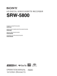
2-1 Control Panel
memory card insertion slot, editing operations
section, tape transport operations section and search
operations section
Upper control panel
DIGITAL VIDEO CASSETTE RECORDER HDW-F500
Lower control panel
Menu operations section
Memory card
insertion slot
Editing operations section
Search operations section
Tape transport operations section
Control panel
Chapter 2
Locations and Functions of Parts and Controls
2-1
Chapter 2 Locations and Functions of Parts and Controls
Chapter 2 Locations
and Functions of Parts and Controls
The control panel consists of the following sections:
• Upper control panel
• Lower control panel: menu operations section,
2-1 Control Panel
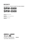
2-1-1 Upper Control Panel
Chapter 2 Locations and Functions of Parts and Controls
1DISPLAY FULL/FINE button
2PHONES jack
3POWER switch
4PHONES level control
5 PB level
6REC level controls
controls
7Audio level meters
8MONITOR SELECT button
DIGITAL VIDEO CASSETTE RECORDER HDW-F500
9Indicator window
!ºINPUT SELECT button
!¡AUDIO INPUT/MONITOR SELECT buttons
!™REFERENCE signal indicators
!£REMOTE buttons and RS-232C indicator
Upper control panel
1 DISPLAY FULL/FINE button
Changes the display range of the audio level meters.
FULL: Display range is –60 to 0 dB (peak level = 0
dB) or –40 to +20 dB (peak level = +20 dB).
Use 814. LEVEL METER SCALE in the VTR
SETUP menu to select the range.
FINE: Displays the audio level in 0.25 dB
increments. The center LED lights up in each
meter as a signal level reference. When the level
exceeds the maximum display value, the top LED
flashes. When the level falls below the minimum
display value, the bottom LED flashes.
2-2
Chapter 2
Locations and Functions of Parts and Controls
2 PHONES jack
Connects stereo headphones with 8 Ω impedance for
audio monitoring during recording, playback, and
editing. Adjust the headphone output level with the
PHONES level control.
3 POWER switch
Turns on the power. When the power is turned on, the
audio level meters and menu display in the lower
control panel light up.
4 PHONES level control
Adjusts the output level to the PHONES jack.
You can enable this control to simultaneously adjust
the output level to the MONITOR OUTPUT
connectors on the connector panel.
5 PB (playback) level controls
Adjust the level of the audio output for channels 1 to 4
and the cue channel.
Pull out the controls during playback to adjust the
audio output for each channel. Push in again for
factory-set levels (+4 dB output for a signal recorded
at a reference level of 0 dB). When pushed in, the
controls cannot adjust the audio output level.
6 REC (recording) level controls
Adjust the recording level for channels 1 to 4 and the
cue channel.
Pull out the controls to adjust the recording level for
each channel in E-E mode1). Push in again for the
factory-set recording level (0 dB reference level for an
input of +4 dB). When pushed in, the controls cannot
adjust the recording level.
7 Audio level meters
Indicate the recording level in recording or E-E mode
or the playback level in playback or CONFI mode.
The display range can be changed by pressing the
DISPLAY FULL/FINE button. The reference level is
factory set at –20 dB, and the peak level at 0 dB.
Indicators and corresponding VTR status
Indicator
CHANNEL
CONDITION
INTERLACE
PsF
23.98
24
25
29.97
30
Status
Indicates the playback signal condition.
Green: Playback signal is good.
Yellow: Playback signal is less than
good, but still reproducible.
Red: Playback signal is poor. Head
cleaning or internal inspection is
necessary if the indicator lights up
continuously.
Lights when the VTR is operating under
the interlace mode(50i/59.94i/60i).
Lights when the VTR is operating under
the PsF mode(23.98PsF/24PsF/25PsF/
29.97PsF/30PsF).
Lights when the VTR is operating with a
frame frequency of 23.98 Hz.
Lights when the VTR is operating with a
frame frequency of 24 Hz.
Lights when the VTR is operating with a
frame frequency of 25 Hz.
Lights when the VTR is operating with a
frame frequency of 29.97 Hz.
Lights when the VTR is operating with a
frame frequency of 30 Hz.
For more information about the selection of the frame
frequency , refer to the supplied Maintenance Manual.
8 MONITOR SELECT button
Selects the audio signal to be output at the MONITOR
OUTPUT L/R connector(s). Press to light the button
up, then press the AUDIO INPUT/MONITOR
SELECT button(s) to specify which channel(s) are to
be monitored at the MONITOR OUTPUT L or R
connector. If you specify more than one channel to the
same MONITOR OUTPUT connector, a mixed audio
signal is output from that connector. This specification
can also be done with setting the VTR SETUP menu
807~808 AUDIO MONITOR L~R select .
For details, see Section 4-6-3, “Selecting the Monitor
Output Signal (MON-L SEL/MON-R SEL)” on page 4-43.
..........................................................................................................................................................................................................
1) E-E mode
An abbreviation for Electric-to-Electric mode. In this
mode, video or audio input signals are passed and output
only through the VTR’s internal circuitry, and not
through the magnetic conversion system comprising tape
and heads.
Chapter 2
Locations and Functions of Parts and Controls
2-3
Chapter 2 Locations and Functions of Parts and Controls
For details, see Section 5-1-2, “Selecting Audio Signals” on
page 5-2.
9 Indicator window
The following indicators light up to indicate the VTR’s
status.
2-1 Control Panel
Chapter 2 Locations and Functions of Parts and Controls
!º INPUT SELECT button
Selects the type and channel for the audio input signal.
Press to light the button up, then press one of the
AUDIO INPUT/MONITOR SELECT buttons to select
the type and the channel of the audio signal.
HD SDI (CH-1 to CH-4): Selects the input signal
from the HD SDI INPUT or SDTI (OPTION) IN
connector.
AES/EBU (CH-1 to CH-4): Selects signal input to
the AUDIO INPUT (AES/EBU) connectors.
ANALOG (CH-1 to CH-4): Selects signal input to
the AUDIO INPUT connectors.
The INPUT SELECT button will flash if there is no
incoming signal and HD SDI or AES/EBU is selected.
This setting can also be done with setting the VTR
SETUP menu 802~805 AUDIO INPUT select
CH1~CH4.
Notes
• When the signal input to the SDTI (OPTION) IN
connector is selected for the input video signal, the
signal input to the SDTI (OPTION) IN connector is
automatically selected for the input audio signal as
well.
• When the audio signal input to the SDTI (OPTION)
IN connector is selected for the input audio signal,
only the INPUT SELECT button lights.
!™ REF SYNC (reference signal) indicators
These indicate the signal selected as the reference
signal. If there is no reference signal input to the
selected connector, the STOP button flashes.
EXT SD: Is lit when the video signal input to the
REF. IN SD connector is acting as the reference
signal.
EXT HD: Is lit when the video signal input to the
REF. IN HD connector is acting as the reference
signal.
INPUT VIDEO: Is lit when the video signal input to
the HD SDI INPUT or SDTI (OPTION) IN
connector is acting as the reference signal.
!£ REMOTE buttons and RS-232C indicator
Press these buttons to select external equipment to be
used to remotely control the VTR.
1(9 pin): Press to select the unit connected to the
REMOTE1-IN(9P)/OUT (9P) connectors. The
button lights up.
2(50 pin): Press to select the unit connected to the
PARALLEL I/O (50P) connector (with optional
BKDW-509). The button lights up.
RS-232C indicator: Lights up when the VTR is
communicating with the external equipment
connected to the RS-232C connector.
Note
For details, refer to “4-6-1 Selecting the Audio Input
Signal” on page 4-43.
!¡ AUDIO INPUT/MONITOR SELECT buttons
Select the audio input signal when the INPUT
SELECT button is lit, or the audio signal to be
monitored when the MONITOR SELECT button is lit.
2-4
Chapter 2
Locations and Functions of Parts and Controls
When the VTR is being controlled by external
equipment connected to the REMOTE1-IN (9P) or
PARALLEL I/O (50P) connector, all tape transport
buttons and edit operation buttons are disabled, except
the STOP and EJECT buttons. You may also specify
the disabling or enabling of all buttons by setting
008.LOCAL FUNCTION ENABLE in the VTR
SETUP menu.
2-1-2 Lower Control Panel (Menu Operations Section)
1Menu display
3MEMORY CARD indicator
Chapter 2 Locations and Functions of Parts and Controls
2Menu buttons
4ACCESS button
DIGITAL VIDEO CASSETTE RECORDER HDW-F500
5Memory card insertion slot
6Function buttons
7ALT button
8MAINTENANCE switch
9ALARM indicator
Lower control panel (menu operations section)
Chapter 2
Locations and Functions of Parts and Controls
2-5
2-1 Control Panel
1 Menu display
Menus selected by pressing the menu buttons appear
here.
Each menu shows the functions assigned to each
function button ([F1] to [F10]) and information
necessary for making settings, such as time codes.
Chapter 2 Locations and Functions of Parts and Controls
2 Menu buttons
Press to activate the respective menu.
HOME button: Activates the HOME menu.
Settings for basic or editing operations are made
in the HOME menu.
TC button: Activates the TC (time code) menu. In
the TC menu, you can switch between LTC and
VITC and between DF and NDF, and make
settings for time code displays on an external
monitor.
CUE button: Activates the CUE menu. In the CUE
menu, you can register 10 cue points per page for
a total of 100 cue points.
PF1 button: Activates the PF (Personal Function) 1
menu. In the PF1 menu, you can register
frequently used settings in other menus. Settings
for video input/output signals are factory set.
PF2 button: Activates the PF (Personal Function) 2
menu. In the PF2 menu, you can register
frequently used settings in other menus. Settings
for audio input/output signals are factory set.
SET UP button: Activates the SET UP menu. Use
the SET UP menu to restore settings to the VTR
memory banks or IC memory card, register
functions to the PF1/2 menus, and set items in the
VTR SETUP menu.
For details, see Chapter 4, “Menu Settings” on page 4-1.
3 MEMORY CARD indicator
Lights up when the memory card is inserted.
The indicator will flash when the memory card is
improperly inserted or when the memory card battery
is dead.
4 ACCESS button
Press this button to directly activate the MEMORY
CARD menu. Flashes when the control panel is
accessing the memory card.
Note
Do not eject the memory card while the ACCESS
button is flashing as this may damage the contents of
the memory card.
2-6
Chapter 2
Locations and Functions of Parts and Controls
5 Memory card insertion slot
Insert memory cards here. VTR settings can be stored
on cards and used to configure the VTR and control
panel at a later date, thus reducing the time required
for set up.
Press the button beside the insertion slot to eject the
memory card.
6 Function buttons
Activates the functions in each menu.
7 ALT (alternative) button
Press to change the functions of the current menu.
Press again to return to the original functions.
8 MAINTENANCE switch
Activates the MAINTENANCE menu.
To operate this switch, push it in using the tip of a pen
or some other pointed object while holding down the
SFT button.
9 ALARM indicator
Flashes when the communication between the VTR
and the control panel is abnormal.
2-1-3 Lower Control Panel (Editing Operations Section)
!ºNumeric buttons and +/– buttons
Chapter 2 Locations and Functions of Parts and Controls
!¡SFT button
!™RCL button
!£CLR button
!¢SET button
DIGITAL VIDEO CASSETTE RECORDER HDW-F500
@™PREREAD indicator
!∞AUDIO IN/OUT buttons
!§IN/OUT buttons
!¶ENTRY button
@¡PLAYER/RECORDER buttons
@ºINPUT CHECK button
!ªAUTO button
!•Cursor control buttons
Lower control panel (editing operations section)
Chapter 2
Locations and Functions of Parts and Controls
2-7
2-1 Control Panel
!º Numeric buttons and +/– buttons
Press to input time data or edit points data at the cursor
position in menu display. Press buttons 0 to 5 while
holding down the SFT button to input A to F
(hexadecimal figures) for user bits. Use the +/–
buttons to increase or decrease settings.
Chapter 2 Locations and Functions of Parts and Controls
!¡ SFT (shift) button
Press buttons 0 to 5 while holding down this button to
input A to F (hexadecimal figures) for user bits.
Use also in combination with other buttons to perform
other operations.
!™ RCL (recall) button
Press to call up a previously entered value.
!£ CLR (clear) button
Press to clear input data.
!¢ SET button
Press to finalize data.
!∞ AUDIO IN/OUT buttons
Press to set AUDIO IN and OUT points during insert
mode. Press either AUDIO IN or OUT button while
holding down the ENTRY button to set an audio edit
point.
!§ IN/OUT buttons
Press to set an IN or OUT point during editing. Press
either button while holding down the ENTRY button
to set an edit point.
!¶ ENTRY button
Press to enter an edit or cue point.
While holding down this button, press either the
AUDIO IN or OUT button, or the IN or OUT button.
!• Cursor control buttons
Press to move the cursor in the menu display. Move
the cursor as required to enter a value using the
numeric buttons, or to change a menu setting.
2-8
Chapter 2
Locations and Functions of Parts and Controls
!ª AUTO button
When this button is pressed, it lights up and auto edit
mode is activated.
@º INPUT CHECK button
While you hold down this button, the input signal is
output from the monitor output connector, so that you
can monitor the input video and audio.
When the LTC/VITC time code is shown on the
display, you can check the time code generator.
Note
When the optional HKDV-501A HD-SD Converter
Board is installed in the unit and VTR SETUP menu
item 776 DOWNCONVERTER INPUT CHECK
ENABLE is set to “enable”, you can monitor
downconverter output. When you press the INPUT
CHECK button, the input video and audio is output
from all HD-SD converter output connectors.
@¡ PLAYER/RECORDER buttons
Select which VTR is to be controlled by this VTR’s
control panel during editing when this VTR is used as
a recorder and an external VTR is connected to the
REMOTE1-IN(9P)/OUT(9P) connectors as a player.
PLAYER: The tape transport buttons and editing
operation buttons on the control panel control the
external player VTR.
RECORDER: The tape transport buttons and
editing operation buttons on the control panel
control the recorder VTR (this VTR).
The PLAYER/RECORDER buttons have no effect
when using this VTR alone.
@™ PREREAD indicator
Lights up during preread mode.
For more information about PREREAD, see “6-2-3
Performing Preread Editing” on page 6-18.
2-1-4 Lower Control Panel (Tape Transport Operations Section)
@£STANDBY button
Chapter 2 Locations and Functions of Parts and Controls
@¢EJECT button
@∞PREROLL button
@§PREVIEW/REVIEW button
DIGITAL VIDEO CASSETTE RECORDER HDW-F500
@¶SERVO indicator
@•STOP button
@ªPLAY button
#ºREC/EDIT button
#¡REC INHIBIT indicator
Lower control panel (tape transport operations section)
@£ STANDBY button
Press this button in other than standby mode to make
it light up and place the VTR in standby mode. The
head drum rotates in standby mode, thereby
shortening the time required for the tape to start.
Press this button while in standby mode to turn the
button off and cancel standby mode. The head drum
stops rotating and the tape tension is released. If the
VTR remains in standby mode for more than eight
minutes (factory setting), standby mode is
automatically canceled in order to safeguard the tape.
@¢ EJECT button
Press to eject the cassette. When the button is pressed,
the tape is automatically unthreaded and the cassette is
ejected in a few seconds. Resets the display when CTL
codes appear in the menu display in the lower control
panel.
Chapter 2
Locations and Functions of Parts and Controls
2-9
2-1 Control Panel
@∞ PREROLL button
Press to position the tape to the preroll point (a
position factory set to five seconds before the IN
point).
Press this button while holding down the IN, OUT,
AUDIO IN or AUDIO OUT button to cue up the tape
at the edit point of the respective button.
Chapter 2 Locations and Functions of Parts and Controls
For details on changing the preroll time, refer to “4-2-7
Setting the Preroll Time (PREROLL TIME)” on page 4-18.
@§ PREVIEW/REVIEW button
After edit points are set, press this button to preview,
on the monitor connected to the recorder, the effect of
the edit before it is performed. In this operation, the
tape runs, but no editing is carried out.
If you press this button after carrying out an edit, the
results of the edit are played back on the monitor
connected to the recorder.
@¶ SERVO indicator
Lights up when the drum servo and capstan servo are
locked.
@• STOP button
When you insert the cassette, the VTR automatically
enters stop mode.
The STOP button flashes when the [F2] (SERVO REF)
button in the PF1 menu is set to input but there is no
video input signal, when the [F2] (SERVO REF)
button in the PF1 menu is set to ext but there is no
external reference video signal, or when the input
signal is out of sync with the external reference video
signal. If you want, you can set 102. REFERENCE
SYSTEM ALARM in the VTR SETUP menu so that
the STOP button will not flash under the above
conditions.
2-10
Chapter 2
Locations and Functions of Parts and Controls
@ª PLAY button
Starts playback.
Press this button while holding down the REC button
to start recording.
Pressing this button during recording or manual editing
changes the VTR to playback mode.
#º REC/EDIT (recording/edit) button
Press this button while holding down the PLAY button
to start recording.
If you press this button in play mode manual editing
begins. After setting edit points, if you press this
button while the AUTO button is lit, automatic editing
is performed.
#¡ REC INHIBIT indicator
The status of this indicator depends on the setting of
the ALT button and [F2] (REC INH) button in the
HOME menu and the state of the record-protect plug
on the cassette.
Status of the REC INHIBIT indicator
Setting of the ALT State of the record- REC INHIBIT
and [F2] (REC INH) protect plug on the indicator
buttons in the
cassette
HOME menu
all
crash REC, video/
CTL, audio/CTL
off
Recording disabled
Lit/flashinga)
Recording allowed
Lit
Recording disabled
Lit/flashinga)
Recording allowed
Unlit
Recording disabled
Lit/flashinga)
Recording allowed
Unlita)
a) Toggle between lit/flashing settings is possible using the
104.REC INHIBIT LAMP FLASHING setting in the
VTR SETUP menu.
Recording, editing, and selection of assemble and
insert modes are possible only when the indicator is
off.
2-1-5 Lower Control Panel (Search Operations Section)
Chapter 2 Locations and Functions of Parts and Controls
#™ VAR button
#£ JOG button
#¢ SHUTTLE button
DIGITAL VIDEO CASSETTE RECORDER HDW-F500
#∞ Search dial
Lower control panel (search operations section)
#™ VAR button
Press to select variable speed playback mode for
noiseless playback in a maximum range of –1 to +2
times normal playback speed, in 51 steps. Playback
exceeding this speed range is not possible. The search
dial clicks at the positions for still-picture and normal
playback speed.
#£ JOG button
Press to select jog mode. In this mode, the button
lights up and playback at –1 to +1 or –2 to +2 times
normal playback speed is possible (determined by the
107. JOG DIAL RESPONSE setting in the VTR
SETUP menu). In this mode, the search dial does not
click.
#¢ SHUTTLE button
Press to enter shuttle mode. In this mode, the button
lights and playback corresponding to the angle of
rotation of the search dial. The playback speed is
different depending on the frame frequency of the unit.
In this mode, the search dial clicks at the positions for
0 (still-picture), –10 and +10 times normal playback
speed.
Frame frequency
Playback speed
23.98/24 Hz
Ranging from –60 to +60
25 Hz
Ranging from –58 to +58
29.97/30 Hz
Ranging from –50 to +50
Chapter 2 Locations and Functions of Parts and Controls
2-11
2-1 Control Panel
Chapter 2 Locations and Functions of Parts and Controls
#∞ Search dial
Rotate to search for edit points. Rotate the dial
clockwise for forward playback (the z indicator lights
up) or counterclockwise for reverse playback (the Z
indicator lights up). The p indicator lights up while
the VTR is in stop mode.
Shuttle mode: The playback speed is different
depending on the frame frequency of the unit. (See
item #¢SHUTTLE button.) The dial clicks at the
positions corresponding to 0 (still-picture), –10
and +10 times normal playback speed.
Jog mode: The playback speed corresponds to the
rotational speed of the dial (–1 to +1 or –2 to +2
times normal playback speed depending on the
107.JOG DIAL RESPONSE setting in the VTR
SETUP menu). The dial does not click.
Variable speed playback mode: Noiseless playback
at –1 times normal speed when the dial is rotated
fully counterclockwise, and +2 times normal
speed when rotated clockwise. The dial clicks at
the positions of still-picture and normal playback
speed.
Capstan override mode: Rotating the dial while
holding down the PLAY button changes the
playback speed by up to ±15%.
After turning the power on, always set the search dial
at the center position (where the p indicator lights up).
2-12
Chapter 2
Locations and Functions of Parts and Controls
2-2 System Set-Up Panel
Lift the lower control panel up to its horizontal
position to access the system set-up panel.
Chapter 2
Accessing the system set-up panel
CONTROL PANEL
EXT
INT
CONTROL PANEL switch
Selects which control panel controls this VTR.
INT: Control is by the control panel attached to
this VTR.
EXT: Control is remote, by connection to the
CONTROL PANEL connector on the rear
panel.
The switch is factory-set to INT.
System set-up panel
Chapter 2
Locations and Functions of Parts and Controls
2-13
Locations and Functions of Parts and Controls
Lower control panel
2-3
Connector
Panel
2-3
Connector
Panel
Chapter 2 Locations and Functions of Parts and Controls
1 REF. OUT 1125 SYNC connectors
8 AUDIO INPUT (AES/EBU)
connectors
2 D CONV. OUT (OPTION) COMPOSITE
(SUPER) connector
9 AUDIO OUTPUT (AES/EBU)
connectors
3 D CONV. OUT (OPTION) SYNC connector
!º HD SDI INPUT connectors
4 REF. IN SD connectors and 75 Ω
termination switch
!¡ HD SDI OUTPUT connectors
5 REF. IN HD connectors and 75 Ω
termination switch
!™ SDTI (OPTION) IN connector
6 BREAKER button
!£ SDTI (OPTION) OUT
connector
7 ⁄AC IN connector and
ground connector
!¢ AUDIO INPUT LEVEL/
600Ω termination switches
@º VIDEO CONTROL
connector
!∞ AUDIO INPUT connectors
@¡ RS-232C connector
!§ AUDIO OUTPUT connectors
@™ PARALLEL I/O (50P) connector
!¶ CONTROL PANEL connector
@£ D CONV. SDI OUT (OPTION)
connectors
!• REMOTE1-IN(9P)/OUT(9P) connectors
@¢ PULL DOWN OUT (OPTION)
connector
!ª MONITOR OUTPUT connectors
@∞ TIME CODE OUT connector
@§ TIME CODE IN connector
Connector panel
Note
For the AUDIO INPUT CH1/2/3/4 CUE connectors,
AUDIO OUTPUT CH1/2/3/4/CUE connectors, as well
as the TIME CODE IN/OUT (XLR, 3 pins)
2-14
Chapter 2
Locations and Functions of Parts and Controls
connectors, the type (male or female) of input/output
connectors used overseas are opposite of those used in
Japan. To use this unit with audio equipment outside
of Japan, you must use male/female adapters.
1 REF. OUT 1125 SYNC connectors (BNC)
Outputs a trilevel sync signal for the external
synchronization. The field frequency is synchronized
to the input video signal.
This connector is operative only when the optional
HKDV-501A HD-SD Converter Board is installed.
3 D CONV. OUT (OPTION) SYNC connector
(BNC)
Outputs an NTSC external sync signal.
Notes
• This is effective only when the optional HKDV-501A
HD-SD Converter Board is installed.
• The phase is the same as the phase of the composite
signal output from the COMPOSITE (SUPER) of D
CONV. OUT (OPTION) connector. Because the
output phase changes with the operation mode of the
VTR, use this to synchronize with the video monitor.
4 REF. IN SD connectors (BNC) and 75 Ω
termination switch
Inputs for a reference video signal (NTSC or PAL) of
the selected field frequency. Use a video signal with
chroma burst (VBS) or a monochrome video signal
(VS).
A loop-through connection is possible. Set the 75 Ω
termination switch to OFF if you are using a loopthrough connection and set it to ON if you are not
using a loop-through connection.
5 REF. IN HD connectors (BNC) and 75 Ω
termination switch
Inputs for a reference video signal (HD) of the selected
field frequency. Use a trilevel SYNC signal for the
external synchronization. A loop-through connection
is possible. Set the 75 Ω termination switch to OFF if
you are using a loop-through connection and set it to
ON if you are not using a loop-through connection.
8 AUDIO INPUT (AES/EBU) connectors (BNC)
Inputs for digital signals in AES/EBU format for
channels 1 to 4.
9 AUDIO OUTPUT (AES/EBU)connectors (BNC)
Outputs digital signals in AES/EBU format for
channels 1 through 4.
!º HD SDI (SDI video/audio) INPUT connectors
(BNC)
The left connector accepts HD SDI video/audio
signals.
Note
The INPUT MONITOR connector is for use with an
input monitor and does not follow the standards for
output.
!¡ HD SDI (SDI video/audio) OUTPUT connectors
(BNC)
Outputs up to four (1 to 4) HD SDI video/audio signal
lines.
Character data such as time codes are superimposed on
the signal from the MONITOR connector when the
ALT/[F6] (CHARA SUPER) setting in the TC menu is
set.
!™ SDTI (OPTION) IN connector (BNC)
Outputs a video/audio SDTI signal.
Note
This connector is operative only when the optional
HKDV-506A SDTI Board is installed.
!£ SDTI (OPTION) OUT connector (BNC)
Inputs a video/audio SDTI signal.
Note
This connector is operative only when the optional
HKDV-506A SDTI Board is installed.
Chapter 2
Locations and Functions of Parts and Controls
2-15
Locations and Functions of Parts and Controls
Note
7 ⁄AC IN connector and connector
Connects to an AC outlet using the power cord
supplied with the VTR.
Chapter 2
2 D CONV. OUT (OPTION) COMPOSITE
(SUPER) connector (BNC)
Outputs an analog composite signal for a video
monitor. When the ALT/[F6] (CHARA SUPER)
setting in the TC menu is on, character signals such as
time codes are superimposed on the output.
6 BREAKER button
Primary circuit breaker for the AC power circuit.
2-3 Connector Panel
Chapter 2 Locations and Functions of Parts and Controls
!¢ AUDIO INPUT LEVEL/600Ω termination
switches
The termination switches should be set for in
ANALOG AUDIO INPUT connector according to the
audio input level and input impedance.
Use OFF for low input levels when:
Audio input level is –60 dBu (microphone input)
and audio input impedance is high (approximately
20 kΩ)
Use OFF for high input levels when:
Audio input level is +4 dBu (line input) and audio
input impedance is high (approximately 20 kΩ)
Use ON for high input levels when:
Audio input level is +4 dBm (line input) and audio
input impedance is 600Ω
!∞ ANALOG AUDIO INPUT connectors
(XLR-3-32)
Accepts up to five analog audio signal lines (channels
1 to 4 and cue).
!§ ANALOG AUDIO OUTPUT connectors
(XLR-3-31)
Outputs up to five analog audio signal lines (channels
1 to 4 and cue).
!¶ CONTROL PANEL connector (15-pin)
Connects the control panel through the 15-pin cable
when using the control panel is used as a remote
controller.
!• REMOTE1-IN (9P)/OUT (9P) connectors
(D-sub 9-pin)
Used with the included 9pin remote control cable to
connect two HDW-F500 VTRs, or a second HD VTR
when a BVE900/910/2000/9000/9100 series BVE
Editing Control Unit is used for editing. Used when
you edit using two VTRs and the BVE-900/910/2000/
9000/9100 Editing Control Unit. The REMOTE1-IN
and OUT connectors can be used to make a bridge
connection.
!ª MONITOR OUTPUT connectors (XLR-3-31)
Outputs signals for audio monitoring. These
connectors output two signal lines: L and R. Select
the signals to be output with the MONITOR SELECT
buttons and the AUDIO INPUT/MONITOR SELECT
buttons on the upper control panel. A setting can be
made so that volume can be controlled with the
PHONES volume knob.
2-16
Chapter 2
Locations and Functions of Parts and Controls
For details, see Section 5-1-2, “Selecting Audio Signals”on
page 5-2.
@º VIDEO CONTROL (Digital Video Processor
Control) connector (D-sub 9-pin)
Connects to the optional HKDV-503 HD Digital Video
Controller to enable remote control of the internal
digital video processor. Turn off the power before
connecting the remote controller.
@¡ RS-232C connector (RS-232C serial interface)
(D-sub 25-pin)
Receives or transmits RS-232C serial remote control
signals and/or VTR status data from/to external
equipment. When this connector is being used for
communication, the RS-232C indicator on the upper
control panel will be lit.
@™ PARALLEL I/O (50P) connector (D-sub 50-pin,
with optional BKDW-509)
Inputs an external remote control signal.
For details, refer to the Maintenance Manual.
@£ D CONV. SDI (D1/D2 SDI video/audio)
(OPTION) OUT connectors (BNC)
Outputs up to three sets of video/audio signals. When
the ALT/[F8] (CHARA SUPER) key of the TC menu
is set to ON, text data such as time codes are
superimposed on the output of connector 3 (SUPER).
Selection of D1/D2 output is made using the [F9]
(OTHERS CHECK)/[F9] (SYSTEM)/[F3] (D-CONV
SDI) button in the MAINTENANCE menu.
Note
This connector is operative only when the optional
HKDV-501A HD-SD Converter Board is installed.
@¢ PULL DOWN OUT (OPTION) connectors
(BNC)
Outputs two sets of 2-3 pull down video/audio signals.
When the ALT/[F5] (PD CHARA) key of the TC
menu is set to ON, text data such as time codes are
superimposed.
Note
This connector is operative only when the optional
HKDV-507 HD PULL DOWN Board is installed.
@∞ TIME CODE OUT connector (XLR-3-31)
Outputs the following time codes according to the
VTR operation mode.
In playback mode: Playback time codes
In recording mode: Time codes generated by the
internal time code generator, or time codes input
to the TIME CODE IN connector.
Chapter 2
Setting
Description
off tape
In playback mode, playback time codes are
selected, and in recording mode, TCH time
code signals are used.
regene
Playback time codes are regenerated and
output only in playback mode when the servo
is locked. In all other cases, output is the
same as for the “off tape” setting.
through
The time code signal from the TIME CODE
IN connector is output as is. (Used during
cascade connections.)
Locations and Functions of Parts and Controls
To select the output signal for the TIME CODE OUT
connector, use the 613.TC OUTPUT SIGNAL IN
REGEN MODE setting in the VTR SETUP menu.
(For more information about cascade
connections, see 3-1-4 Cascade
Connections on page 3-4.)
@§ TIME CODE IN connector (XLR-3-32)
Accepts external time codes for recording to tape.
Connect to the time code output connector of the
external equipment.
Chapter 2
Locations and Functions of Parts and Controls
2-17
3-1 Connecting External Equipment
Chapter 3 Setting Up the VTR
Chapter 3 Setting Up the
VTR
3-1-1 Making Digital Connections
This example shows how to connect the HDD/HDDP1000 1 inch HD Digital VTR and use it as the player
REMOTE (9Pin)
with the HDW-F500 acting as the recorder in the
59.94i or 60i mode.
HDD/HDDP-1000
DIGITAL AUDIO
50 PIN PARALLEL
DIGITAL VIDEO
OUTPUT
CH-3/4
9 pin remote cable
CH-1/2
XLR/BNC
Converter
P/S Converter
HD SDI OUTPUT
HD SDI OUTPUT
REMOTE 1-IN (9P)
Video monitor
(HD serial monitor)
Making digital connections
Refer to the “Specifications” section in the appendix (page
A-2) for recommended XLR/BNC and P/S converters.
Chapter 3 Setting Up the VTR
3-1
3-1 Connecting External Equipment
3-1-2 Making HD Analog Connections
This example shows how to connect the VTR when
using HD analog audio and video signals in the 60i
mode.
HDV-10 1/2 inch VTR
or other player
REMOTE (9P)
Chapter 3
ANALOG VIDEO
OUTPUT
Setting Up the VTR
ANALOG AUDIO
OUTPUT CH-1 to 4
9-pin remote cable
HKPF-101 A/D
Converter
HD SDI OUTPUT
HD SDI OUTPUT
HKPF-102 D/A
Converter
REMOTE 1-IN (9P)
Set the analog audio input level and
impedance using the AUDIO INPUT
LEVEL/600Ω termination switches as
follows:
For line input with a 600Ω termination:
HIGH and ON
For high-impedance line input: HIGH
and OFF
For high-impedance microphone input:
LOW and OFF
3-2
Chapter 3
Setting Up the VTR
ANALOG VIDEO
OUTPUT
Video monitor (HD
monitor)
3-1-3 Making NTSC/PAL Digital Connections
This example shows how to connect two VTRs
together, using an HDW-F500 as the players and a
DVR-2100 D-1 Component Digital VTR as the
recorder.
HDW-F500 (Player)
[Input]
Chapter 3
COMPOSITE
VIDEO OUTPUT
9 pin remote cable
BNC cable
BNC cable
REMOTE 1-IN
Setting Up the VTR
D CONV. SDI OUT (OPTION)
(D1 SDI)
SDI INPUT
REMOTE-1
[output]
Video monitor
(NTSC/PAL monitor)
DVR-2100 (Recorder)
Note
For color frame editing using the HDW-F500 as the
player and an NTSC/PAL digital device as the
recorder, set 005.SERVO/AV REFERENCE select in
the VTR SETUP menu to external and set
006.EXTERNAL REFERENCE select to extern SD.
Chapter 3 Setting Up the VTR
3-3
3-1 Connecting External Equipment
3-1-4 Cascade connection
This example shows how to connect multiple HDW-F500 VTRs together for simultaneous recording.
HDW-F500 (Player)
HD SDI OUTPUT
Chapter 3
HDW-F500 (Recorder)
BNC cable
Setting Up the VTR
TIME CODE OUT
TIME CODE IN
HD SDI OUTPUT
HD SDI INPUT
Digital video
distributor
HKPF-103M
HDW-F500 (Recorder)
Note
On the recording VTRs, set 613.TC OUTPUT
3-4
Chapter 3
Setting Up the VTR
TIME CODE IN
TIME CODE OUT
Video monitor(HD serial
monitor)
HD SDI INPUT
SIGNAL IN REGENE MODE in the VTR SETUP
menu to through.
3-2 Reference Signals for Video Output and Servo
System
This section describes how reference signals for the
video output and servo system are selected.
3-2-1 Reference Signals for Output Video
Depending on the operating condition, VTR SETUP
menu setting, and the input signal, the video output
signal from the VTR can be synchronized as follows.
Chapter 3
Start
What is
the 005.SERVO/AV
REFERENCE select setting
in the VTR SETUP
menu?
Setting Up the VTR
ext
input
auto
Is the VTR currently
recording or is EDIT
PRESENT on?
Yes
No
What is the 006.
EXTERNAL REFERENCE
select setting in the VTR
SETUP menu?
extrn SD
extrn HD
Is there a signal of the
correct frequency on the
REF. IN HD connector?
Yes
Is there a signal of the
correct frequency on the
REF. IN SD connector?
Yes
No
No
Synchronization
with the reference
video signal input
to the REF. IN HD
connector
Synchronization
with the video
signal input to the
REF. IN SD
connector
Is there an input
signal on the connector
selected by the 701.VIDEO
INPUT select setting
in the VTR
SETUP?
Yes
No
Synchronization
with the video
signal input
designated by the
701.VIDEO INPUT
select setting
No external synchronization (synchronization is internal)
Chapter 3 Setting Up the VTR
3-5
3-2 Reference Signals for Video Output and Servo System
3-2-2 Reference Signals Connections
Make the reference signal connections as follows,
according to your recording or playback requirements.
Reference signal connections
For recording signals from a switcher or signal generator
Chapter 3
Reference signal
Setting Up the VTR
Switcher or signal generator
REF. IN
HD SDI INPUT
75Ω termination switch: ON
For recording signals from a switcher or signal generator
For recording signals from a HD VTR
Reference signal
REF. IN
HD SDI INPUT
HDW-F500 (Recorder)
75Ω termination switch: OFF
HD SDI OUTPUT
HDW-F500 (Player)
75Ω termination switch: ON
For recording signals from a HD VTR
3-6
Chapter 3
Setting Up the VTR
For playback
Reference signal
REF. IN
HD SDI OUTPUT
1/2/3/MONITOR
HD serial input monitor
Chapter 3
Setting Up the VTR
75Ω termination switch: ON
Note
The following signals can be used as a reference
signal.
• HD trilevel SYNC signal of an appropriate field
frequency for the external synchronization
• Black burst signal of 525/59.94 Hz
• Black burst signal of 625/50 Hz
Input the signal of the appropriate field frequency for
your system.
Chapter 3 Setting Up the VTR
3-7
3-3
Handling
Cassettes
3-3
Handling
Cassettes
3-3-1 Recommended Cassettes
Use 1/2 inch HDcam cassettes.
The maximum recording time is as shown in the
following table.
System
frequency
29.97/30 Hz
HDcam
cassette
S-size cassette
40 minutes
L-size cassette
25 Hz
23.98/24 Hz
48 minutes
50 minutes
3-3-2 Inserting and Ejecting
Cassettes
Always turn on the VTR before attempting to insert or
eject cassettes.
Inserting a cassette
124 minutes 149 minutes 155 minutes
Chapter 3
1
Note
Setting Up the VTR
2
Digital Betacam cassettes cannot be used.
S-size cassette
Storage of cassettes
Store your cassettes at room temperature and normal
humidity.
L-size cassette
Inserting a cassette
1
2
Turn the POWER switch to ON.
Before inserting a cassette, check the following
points:
• There is no slack in the tape.
• An error message does not appear in the menu
display.
• The window of the cassette is facing up.
If there is any slack in the tape, refer to “Removing
slack in the tape” on next page.
When inserting an S-size cassette, make sure it is
aligned with the marks on the cassette insertion
slot.
The cassette is loaded automatically, and the tape is
wound around the drum.
3-8
Chapter 3
Setting Up the VTR
Removing slack in the tape
Press one of the reels in slightly, then carefully rotate it
in the direction of the arrow until it stops.
3-3-3 Preventing Accidental
Erasure
To prevent accidental erasure of material recorded on a
tape, push in the record-protect plug.
L-size cassette
Chapter 3
S-size cassette
Setting Up the VTR
Removing slack in the tape
Preventing double cassette inserting
When a cassette is loaded, an orange lock-out bar
appears in the cassette insertion slot to prevent users
from attempting to load another cassette.
Push in the record-protect plug.
To restore the tape for recording, return the plug to its
original position.
Preventing accidental erasure
Ejecting the cassette
Press the EJECT button.
The tape is unthreaded and the cassette is
automatically ejected. This operation takes a few
seconds.
When a cassette with this plug pushed in is inserted
into the VTR, the REC INHIBIT indicator on the
lower control panel lights up and recording will not
start, even if you press the REC button.
To restore the tape for recording, return the plug to its
original position.
To cancel ejecting a cassette
Press any operation button before the cassette is
completely ejected. The cassette is loaded again and
the operation corresponding to the button you pressed
starts.
Chapter 3 Setting Up the VTR
3-9
4-1 Registering and Storing Menu Settings
4-1-1 Menu Configuration
This VTR has two kinds of menus.
PF1&2 ASSIGN menu
This menu contains items that can be registered to the
PF1/2 menus.
Press the [F4] (PF1&2 ASSIGN) button in the SET UP
menu to display this menu.
For details on registering items in the PF1&2 ASSIGN
menu to the PF1/2 menus, see Section 4-1-3, “Registering
Items to the PF1/2 Menus” on page 4-3.
The menu configuration of the VTR is shown in the
figure below,
HOME menu
PF1&2
ASSIGN menu
TC menu
PF1 menu
PF2 menu
Registration
CUE menu
VTR SETUP
menu
SETUP menu
[F4] (PF1&2 ASSIGN) button
[F6] (VTR SETUP) button
Menu configuration
• All items in the HOME, TC, and CUE menus can be
duplicated and registered to the PF1/2 menus.
• Most items in the VTR SETUP menu can be
registered to the PF1/2 menus.
Chapter 4
Menu Settings
4-1
Menu Settings
For details on setting operating conditions of the VTR, see
Section 4-7-1, “VTR SETUP Menu” on page 4-46.
Chapter 4
VTR SETUP menu
This menu contains items that specify the initial
operating conditions of the VTR. You can change
these settings directly without registering the items to
the PF1/2 menus.
Press the [F6] (VTR SETUP) button in the SET UP
menu to display this menu.
Chapter 4 Menu Settings
The operating conditions of the VTR are set using the
menu operation section on the lower control panel.
Menu items are divided among six different menus
(HOME, TC, CUE, PF1, PF2, SET UP).
Of these menus, the PF1/PF2 (Personal Function)
menus can be used to register frequently used menu
items from the other menus, allowing faster setting of
VTR operating conditions. Eight VTR memory banks
are provided for storing up to eight sets of menu
settings. The contents of the eight VTR memory
banks can, in turn, be stored on a memory card for
later recall.
4-1 Registering and Storing Menu Settings
4-1-2 Changing Menu Settings
2
To activate the HOME, TC, CUE, PF1, PF2, or SET
UP menu, press the respective menu button.
Menu items are assigned to function buttons ([F1] to
[F10]) in each menu. When two items are registered to
the same function button, you can display the second
item by pressing the ALT button.
The example below describes the procedure for
changing the setting specified by the ALT button and
[F5] (CAP LOCK) button in the HOME menu.
Press the ALT button.
The second page of the HOME menu appears in
the display.
PRE
READ
off
ÅLT+HOME
REMAIN-T CH.COND
L 113min G R E E N
PLÅY
TCR
LOCK
NDF 2FD F1
01Ó 04µ 58ß 00ƒ
ÅIN 00:01:10:00 ÅOUT 00:02:10:00
IN 00:01:10:00
OUT 00:02:10:00
FREEZE
1
CÅP
LOCK
PREROLL
2FD
5sec
DMC
STOP
CODE
LÅST
EDIT
off
Chapter 4
To return to the first page
Press the ALT button again.
Menu Settings
3
23
Press the [F5] (CAP LOCK) button to change the
capstan servo lock mode setting.
Each time the button is pressed, the setting
changes.
Changing menu settings
1
Press the HOME button.
The first page of the HOME menu appears in the
display.
PB/EE
HOME
REMAIN-T CH.COND
L 113min G R E E N
PLÅY
PB
LOCK
TCR
RECINH
off
ÅSSEMBLE
2FD F1
01Ó 04µ 58ß 00ƒ
ÅIN 00:01:10:00 ÅOUT 00:02:10:00
IN 00:01:10:00
OUT 00:02:10:00
off
INS
TC
off
4-2
INS
VIDEO
INS
Å-CH1
INS
Å-CH2
INS
Å-CH3
INS
Å-CH4
INS
CUE
off
off
off
off
off
off
Chapter 4
Menu Settings
Changing menu settings using the cursor
control buttons
You may also use the cursor control buttons to select
menu items and change menu settings by moving the
on-screen cursor.
For settings which cannot be made by the function
buttons alone, the following icons appear in the
bottom-right of the menu to indicate the use of the
cursor control buttons:
: All cursor control buttons
: Cursor control buttons for horizontal
direction
: Cursor control buttons for vertical direction
In addition to operations using the cursor control
buttons, some menus allow you to change a value by
using the [+]/[–] buttons.
4-1-3 Registering Items to the
PF1/2 Menus
PF1
ÅLT+
PF1
You can register up to 40 items to the PF (Personal
Function) 1/2 menus, including items that are
displayed when the ALT button is pressed. The
registration of items from different menus to the PF1/2
menus eliminates the need for changing menus in
order to change a given VTR operating condition.
Current setting
PF2
Item currently
registered to the
button
For details on the factory-set PF1/2 menus, see Section 4-5,
“PF1 Menu (Factory Settings)” on page 4-38 and 4-6,
“PF2 Menu (Factory Settings)”on page 4-42.
Registering items to the PF1/2 menus
TCR 00:00:00:00
PF ASSIGN MENU
SETUP ITEM-755
755:MASTER(D1)
756:Y LEVEL(D1)
757:B-Y LVL(D1)
758:R-Y LVL(D1)
759:VD OUT(D2)
760:CHROMA(D2)
761:HUE(D2)
762:SETUP(D2)
763:SYNC(NTSC)
764:FINE(NTSC)
SÅVE/
CANCEL EXIT
To unregister the selected item
Press the [F6] (SET BLANK) button.
5
4,5
Press the F button to move the cursor (z) to the
PF1&2 ASSIGN menu, then press the G or g
button to move the cursor to the menu item to be
registered to the function button.
To scroll the menu faster
Press the G or g button while holding down the
SFT button.
PF1
ÅLT+
PF1
6 81
PF2
Registering items to the PF1/2 menus
1
Press the SET UP button.
The SET UP menu appears in the display.
2
Press the [F4] (PF1&2 ASSIGN) button.
The PF1&2 ASSIGN menu appears in the display.
3
4
Press the [F1], [F2], [F3] or [F4] button to select the
PF menu where you wish to register an item.
The selected PF menu appears and the items
currently registered to the menu appear at the left
of the display.
Press the G or g button to move the cursor (z) to
the function button where the item is to be
registered.
The selected function button is highlighted and the
current setting is displayed.
ÅLT+
PF2
REMAIN-T CH.COND
L 113min
PF1
F1KEY
1:701
VIDEO
2:005
IN
3:
SDI
4:708
5:709
6:7160
7:711
8:712
9:713
10:714
SET
BLÅNK PÅSTE
PF ASSIGN
TCR 00:00:00:00
PF ASSIGN MENU
SETUP ITEM-760
755:MASTER(D1)
756:Y LEVEL(D1)
757:B-Y LVL(D1)
758:R-Y LVL(D1)
759:VD OUT(D2)
760:CHROMA(D2)
761:HUE(D2)
762:SETUP(D2)
763:SYNC(NTSC)
764:FINE(NTSC)
SÅVE/
CANCEL EXIT
Item to be
registered to the
function button
6
Press the [F7] (PASTE) button to register the item.
The new item is registered to the function button.
7
Repeat Steps 3 to 6 to register more items.
To cancel the registration of all new items
Press the [F9] (CANCEL) button.
8
Press the [F10] (SAVE/EXIT) button to save the
newly registered items.
The registration is completed and the SET UP
menu appears in the display again.
Chapter 4
Menu Settings
4-3
Menu Settings
2
PF1
F1KEY
1:701
VIDEO
2:005
IN
3:
SDI
4:708
5:709
6:710
7:711
8:712
9:713
10:714
SET
BLÅNK PÅSTE
Chapter 4
3
ÅLT+
PF2
PF ASSIGN
REMAIN-T CH.COND
L 113min
4-1 Registering and Storing Menu Settings
4-1-4 VTR Memory Bank
Function
Storing the current VTR menu settings to
a VTR memory bank
Eight VTR memory banks are provided for storing up
to eight sets of menu settings including items
registered to the PF1/2 menus with titles.
The contents of all eight VTR memory banks can be
stored on a memory card.
Current menu settings in the
VTR (CURRENT SETUP).
These settings are stored
outside the VTR memory
banks even when the power
is off.
6,7
2
4 3 81
Storing/recalling
CLR button
5
Storing the current VTR menu settings to a VTR memory bank
Chapter 4
Menu Settings
Storing/recalling
VTR memory banks (SETUP
BANK1 to 8 and F). SETUP
BANKF contains the factoryset menu settings. By calling
up SETUP BANK F, you can
restore all menu items to their
factory settings.
1
Press the SET UP button.
The SET UP menu appears in the display.
2
Press the [F1] (VTR BANK) button.
The VTR BANK menu appears in the display.
VTR BÅNK
FOOTBALL
TCR 00:00:00:00
VTR BÅNK
VTR BÅNK
CURRENT SETUP
SETUP BÅNK7
1 (Preset)
BASEBALL
ç
2 (Preset)
3 (Preset)
4 (Preset)
5 (Preset)
6 (Preset)
7 FOOTBALL
8 (Preset)
ƒ (Preset)
CH.COND
Memory card (SETUP
BANK 0 to 8). The card
stores setting data in same
way as the VTR memory
banks. These contents can
be later called up in the
VTR.
Storing/recalling
UNDO
VTR memory bank function
For details on memory card use, refer to “4-1-5 Memory
Card Function” on page 4-6.
For details on adding titles to the contents of the VTR
memory bank, refer to “4-1-6 Adding Titles to the Data” on
page 4-11.
Note
EDIT
TITLE
DIRECTION
COPY
EXIT
?
3
Press the [F8] (DIRECTION) button or press the f
or F buttons twice to select the / direction.
4
Press the f button to move the cursor (z) to
CURRENT SETUP[C], then press the [F6] (EDIT
TITLE) button to add a title to the current menu
settings of the VTR.
The contents of SETUP BANKF cannot be changed.
For details, refer to “4-1-6 Adding Titles to the Data”
on page 4-11.
5
4-4
Chapter 4
Menu Settings
Press the F button to move the cursor (z) to
SETUP BANK, then press the G or g button to
move the cursor to the number of the VTR
memory bank to be used for saving the current
menu settings.
6
Press the [F9] (COPY) button.
A message appears in the display asking you to
confirm the operation.
Recalling menu settings from a VTR
memory bank
To cancel the storage operation
Press the CLR button.
7
5,6
2
Press the [F9] (COPY) button while holding down
the SFT button.
The current menu settings are stored to the VTR
memory bank.
Recalling menu settings from a VTR memory bank
1
Press the SET UP button.
The SET UP menu appears in the display.
2
Press the [F1] (VTR BANK) button.
The VTR BANK menu appears in the display.
B
ABCDEFGHIJKLMNOPQRSTUVWXYZ
abcdefghjiklmnopqrstuvwxyz
0123456789[]()<>@+-*=!?:;
$ # % & , . " \ ^ _ ' / ~ '{ }
HD1D2CAM
BÅCK
SPÅCE
SET
LETTER
CÅNCEL
VTR BÅNK
FOOTBALL
TCR 00:00:00:00
VTR BÅNK
VTR BÅNK
CURRENT SETUP
SETUP BÅNK7
1 (Preset)
BASEBALL
ç
2 (Preset)
3 (Preset)
4 (Preset)
5 (Preset)
6 (Preset)
7 FOOTBALL
8 (Preset)
ƒ (Preset)
CH.COND
UNDO
SPÅCE
4
Menu Settings
EDIT TITLE
3 71
Chapter 4
To add or change a title for VTR settings
after storing them to the VTR memory bank
Move the cursor (z) to the number of the VTR
where the settings are stored, then press the [F6]
(EDIT TITLE) button.
SÅVE/
EXIT
For more information, refer to “4-1-6 Adding Titles to
the Data” on page 4-11.
EDIT
TITLE
DIRECTION
COPY
EXIT
?
Recovering previous settings after new
settings have been saved
Press the [F2] (UNDO) button to recover the
previous settings.
Preventing accidental erasure after saving
settings
Move the cursor to the memory bank to be
protected and press ALT/[F2] (PROTECT)
buttons. A will appear next to the selected bank.
8
Press the [F10] (EXIT) button.
The SET UP menu appears again.
3
Press the [F8] (DIRECTION) button or press the f
or F buttons twice to select the ? direction.
4
Press the G or g button to move the cursor (z) to
the number of the VTR memory bank to be
recalled.
5
Press the [F9] (COPY) button.
A message asking you to confirm the operation
appears in the display.
To cancel the recalling operation
Press the CLR button.
(Continued)
Chapter 4
Menu Settings
4-5
4-1 Registering and Storing Menu Settings
6
Press the [F9] (COPY) button while holding down
the SFT button.
The menu settings are recalled from the selected
VTR memory bank.
When the recalling process has been completed,
the title of the VTR bank appears under
CURRENT SETUP in the display.
VTR BÅNK
FOOTBALL
TCR 00:00:00:00
VTR BÅNK
VTR BÅNK
CURRENT SETUP
SETUP BÅNK7
1 (Preset)
BASEBALL
ç
2 (Preset)
3 (Preset)
4 (Preset)
5 (Preset)
6 (Preset)
7 FOOTBALL
8 (Preset)
ƒ (Preset)
CH.COND
UNDO
Chapter 4
EDIT
TITLE
DIRECTION
COPY
EXIT
?
Notes
• Be sure to insert the memory card fully. If the
memory card is not inserted properly, the MEMORY
CARD indicator will flash. If this happens, reinsert
the memory card.
• If the battery in the memory card is dead, the
MEMORY CARD indicator will flash. If this
happens, replace the battery in the memory card.
• The ACCESS button flashes while the VTR is
writing to or reading from a memory card. Do not
eject the memory card while the indicator is flashing.
Formatting a memory card
The supplied memory card or other memory cards
must be formatted before you can use them.
Menu Settings
3,4,5
7
2
Press the [F10] (EXIT) button.
The SET UP menu appears again.
4-1-5 Memory Card Function
You can store menu settings in the VTR memory
banks and cue point data to an memory card for recall
later.
The MEMORY CARD indicator lights up when you
insert a memory card.
You can then access the MEMORY CARD menu
directly from other menus (HOME/TC/CUE/PF1/PF2)
by pressing the ACCESS button.
1
Formatting a memory card
1
Insert the memory card.
The MEMORY CARD indicator lights up.
2
Press the ACCESS button.
MEMORY CARD menu appears in the display.
MEMORY CARD indicator
FORMÅT
CÅRD
ACCESS button
UNDO
SHOW
SETUP
SHOW
CUESET
/
Memory card insertion slot
Memory card function
To eject the memory card
Press the button on the right side of the insertion slot.
4-6
Chapter 4
Menu Settings
MEMORY CÅRD
FOOTBALL
TCR 00:00:00:00
MEMORY CÅRD
VTR BÅNK
CARD BÅNK0
CURRENT SETUP
BÅSEBÅLL 0
ç FOOTBALL
( P r e s e t.).. 1
1 (Preset)
(Preset) 2
2 (Preset)
(Preset) 3
3 (Preset)
(Preset) 4
4 (Preset)
(Preset) 5
5 (Preset)
(Preset) 6
6 (Preset)
FOOTBALL 7
7 FOOTBALL
(Preset) 8
8 (Preset)
ƒ (Preset)
EDIT SELECT DIRECCOPY
EXIT
TITLE
ÅLL
TION
CH.COND
3
Press the [F1] (FORMAT CARD) button.
A message asking you to confirm the operation
appears in the display.
4
Press the [F1] (FORMAT CARD) button while
holding down the SFT button.
A message asking you to confirm the operation
appears in the display again.
5
Press the [F1] (FORMAT CARD) button while
holding down the SFT button.
The VTR starts formatting the card.
4
Move the cursor to the VTR side using the [>]
button and use the G and g buttons to move the
cursor to the memory bank where the data is to be
saved.
FORMÅT
CÅRD
UNDO
SHOW
SETUP
To cancel formatting
Press the CLR button while the confirmation
message appears in the display.
SHOW
CUESET
MEMORY CÅRD
TENNIS
TCR 00:00:00:00
MEMORY CÅRD
VTR BÅNK
CARD BÅNK4
SETUP BANK 2
BÅSEBÅLL 0
ç FOOTBALL
( P r e s e t.).. 1
1 (Preset)
(Preset) 2
2 TENNIS
(Preset) 3
3 (Preset)
(Preset) 4
4 (Preset)
(Preset) 5
5 (Preset)
(Preset) 6
6 (Preset)
FOOTBALL 7
7 FOOTBALL
(Preset) 8
8 (Preset)
ƒ (Preset)
EDIT SELECT DIRECCOPY
EXIT
TITLE
ÅLL
TION
CH.COND
Destination
?
Storing the contents of the VTR memory
banks to a memory card
2 7,8
Chapter 4
To store the current VTR menu settings
Move the cursor (z) to the [C] (CURRENT
SETUP) position.
5
6 3 91 4,5
Move the cursor to the MEMORY CARD side
using the [>] button, and use the G and g buttons
to move the cursor (z) to the bank number
(MEMORY CARD side) where the data is to be
saved.
Storing the contents of the VTR memory banks to a memory card
1
2
FORMÅT
CÅRD
Press the SET UP button.
The SET UP menu appears in the display.
Press the [F2] (MEMORY CARD) button.
The MEMORY CARD menu appears in the
display.
You can access the MEMORY CARD menu
directly by pressing the ACCESS button.
FORMÅT
CÅRD
UNDO
SHOW
SETUP
SHOW
CUESET
MEMORY CÅRD
FOOTBALL
TCR 00:00:00:00
MEMORY CÅRD
VTR BÅNK
CARD BÅNK0
CURRENT SETUP
BÅSEBÅLL 0
ç FOOTBALL
( P r e s e t.).. 1
1 (Preset)
(Preset) 2
2 TENNIS
(Preset) 3
3 (Preset)
(Preset) 4
4 (Preset)
(Preset) 5
5 (Preset)
(Preset) 6
6 (Preset)
FOOTBALL 7
7 FOOTBALL
(Preset) 8
8 (Preset)
ƒ (Preset)
EDIT SELECT DIRECCOPY
EXIT
TITLE
ÅLL
TION
CH.COND
/
3
UNDO
VTR memory
bank number
SHOW
SETUP
SHOW
CUESET
MEMORY CÅRD
TENNIS
TCR 00:00:00:00
MEMORY CÅRD
VTR BÅNK
CARD BÅNK4
SETUP BANK 2
BÅSEBÅLL 0
ç FOOTBALL
( P r e s e t.).. 1
1 (Preset)
(Preset) 2
2 TENNIS
(Preset) 3
3 (Preset)
(Preset) 4
4 (Preset)
(Preset) 5
5 (Preset)
(Preset) 6
6 (Preset)
FOOTBALL 7
7 FOOTBALL
(Preset) 8
8 (Preset)
ƒ (Preset)
EDIT SELECT DIRECCOPY
EXIT
TITLE
ÅLL
TION
CH.COND
?
6
To change the title of the bank, press the [F6]
(EDIT TITLE) button.
For details, refer to “4-1-6 Adding Titles to the
Data”on page 4-11.
7
Press the [F9] (COPY) button.
A message asking you to confirm the operation
appears in the display.
(Continued)
Press the [F8] (DIRECTION) button or press the
[<] or [>] buttons twice to select the ? direction.
Chapter 4
Menu Settings
4-7
Menu Settings
To store all VTR memory banks
Press the [F7] (SELECT ALL) button.
4-1 Registering and Storing Menu Settings
8
Press the [F9] (COPY) button while holding down
the SFT button.
The control panel stores the specified VTR
memory bank to the IC memory card.
After the storage is complete, the title of the VTR
memory bank appears under the MEMORY CARD
indication.
UNDO
SHOW
SETUP
SHOW
CUESET
TENNIS
TCR 00:00:00:00
VTR BÅNK
SETUP BANK 2
ç FOOTBALL
1 (Preset)
2 TENNIS
3 (Preset)
4 (Preset)
5 (Preset)
6 (Preset)
7 FOOTBALL
8 (Preset)
ƒ (Preset)
SELECT DIRECCOPY
EXIT
ÅLL
TION
UNDO
MEMORY CÅRD
CARD BÅNK4
BÅSEBÅLL 0
( P r e s e t.).. 1
(Preset) 2
(Preset) 3
TENNIS
4
(Preset) 5
(Preset) 6
FOOTBALL 7
(Preset) 8
EDIT
TITLE
Press the [F2] (MEMORY CARD) button.
The MEMORY CARD menu appears in the
display.
You can access MEMORY CARD menu directly
from any menu screen by pressing the ACCESS
button.
FORMÅT
CÅRD
MEMORY CÅRD
CH.COND
FORMÅT
CÅRD
2
SHOW
SETUP
SHOW
CUESET
MEMORY CÅRD
TENNIS
TCR 00:00:00:00
MEMORY CÅRD
VTR BÅNK
CARD BÅNK4
SETUP BANK 2
BÅSEBÅLL 0
ç FOOTBALL
( P r e s e t.).. 1
1 (Preset)
(Preset) 2
2 TENNIS
(Preset) 3
3 (Preset)
TENNIS
4
4 (Preset)
(Preset) 5
5 (Preset)
(Preset) 6
6 (Preset)
FOOTBALL 7
7 FOOTBALL
(Preset) 8
8 (Preset)
ƒ (Preset)
EDIT SELECT DIRECCOPY
EXIT
TITLE
ÅLL
TION
CH.COND
?
Chapter 4
?
Menu Settings
Preventing accidental erasure after saving
settings
Press ALT/[F2] (PROTECT) buttons and a
symbol will appear to the right of the memory card
bank number
9
3
Press the [F4] (SHOW CUESET) button.
The display for storing cue point lists appears.
MEMORY CÅRD
TENNIS
TCR 00:00:00:00
MEMORY CÅRD
VTR BÅNK
CUE POINT SET1
CURRENT CUESET
UNDO
(Blank)
1
ç TENNIS
(Blank)
2
ƒ (Blank)
(Blank)
3
SHOW
(Blank)
4
SETUP
(Blank)
5
(Blank)
6
(
B
l
a
n
k
)
7
SHOW
8
(Blank)
CUESET
FORMÅT
CÅRD
Press the [F10] (EXIT) button.
The SET UP menu or the menu displayed before
you pressed the ACCESS button appears again.
EDIT
TITLE
SELECT DIRECÅLL
TION
Storing cue point lists to a memory card
You can store up to 8 pages of cue point lists to a
memory card along with titles.
2 3 6,7
8 4 91
4
Press the [F8] button or press the [<] or [>] buttons
twice to select the ? direction.
5
Press the G or g button to move the cursor (z) to
the number of the memory bank in the memory
card where you want to store the cue point list.
5
Press the SET UP button.
The SET UP menu appears in the display.
MEMORY CÅRD
TENNIS
TCR 00:00:00:00
MEMORY CÅRD
VTR BÅNK
CUE POINT SET1
CURRENT CUESET
UNDO
(Blank)
1
ç TENNIS
(Blank)
2
ƒ (Blank)
(Blank)
3
SHOW
(
B
l
a
n
k
)
4
SETUP
(Blank)
5
(Blank)
6
(Blank)
7
SHOW
8
(Blank)
CUESET
FORMÅT
CÅRD
Bank number in
the memory card
EDIT
TITLE
SELECT DIRECÅLL
TION
?
4-8
Chapter 4
Menu Settings
EXIT
To return to the MEMORY CARD menu
Press the [F3] (SHOW SETUP) button.
Storing cue point lists to an IC memory card
1
COPY
/
COPY
EXIT
6
Press the [F9] (COPY) button.
A message asking you to confirm the operation
appears in the display.
FORMÅT
CÅRD
UNDO
7
8
Press the [F9] (COPY) button while holding down
the SFT button.
The VTR stores the cue point list to the memory
card.
SHOW
CUESET
Press the [F6] (EDIT TITLE) button to add a title
to the cue point list.
For details, refer to “4-1-6 Adding Titles to the
Data”on page 4-11.
/
3
Press the [F8] (DIRECTION) button or press the
[<] or [>] buttons twice to select the / direction.
4
Move the cursor to the memory card side using the
[<] button and use the G or g buttons to place the
cursor (z) by the memory bank where the settings
were saved.
Press the [F10] (EXIT) button.
The SET UP menu or the menu displayed before
you pressed the ACCESS button appears again.
UNDO
Bank number in
the memory card
SHOW
CUESET
Recalling the contents of a memory card
The contents stored in a memory card can be recalled
to the current VTR memory bank.
2 7,8
SHOW
SETUP
MEMORY CÅRD
BASEBALL
TCR 00:00:00:00
MEMORY CÅRD
VTR BÅNK
CARD BANK0
SETUP BANK 2
BÅSEBÅLL 0
ç FOOTBALL
.. 1
( P r e s e t.)
1 (Preset)
(Preset) 2
2 TENNIS
3 (Preset)
(Preset) 3
TENNIS
4
4 (Preset)
(Preset) 5
5 (Preset)
(Preset) 6
6 (Preset)
FOOTBALL 7
7 FOOTBALL
(Preset) 8
8 (Preset)
ƒ (Preset)
EDIT SELECT DIRECCOPY
EXIT
TITLE
ÅLL
TION
CH.COND
/
5
To change the title of the memory bank, press the
[F6] (EDIT TITLE) button.
The title can be also be changed after the settings
are recalled.
For details, refer to“4-1-6 Adding Titles to the Data”on
page 4-11.
5 3 91 4,6
(Continued)
Recalling the contents of an IC memory card
1
Press the SET UP button.
The SET UP menu appears in the display.
2
Press the [F2] (MEMORY CARD) button.
The MEMORY CARD menu appears in the
display.
You can access MEMORY CARD menu directly
from anu menu screen by pressing the ACCESS
button.
Chapter 4
Menu Settings
4-9
Menu Settings
FORMÅT
CÅRD
Chapter 4
Preventing accidental erasure after saving
settings
Move the cursor (z) to the cue point set number you
wish to save and press ALT/[F2] (PROTECT) buttons.
A symbol will appear to the right of the cue point set
number.
9
SHOW
SETUP
MEMORY CÅRD
TENNIS
TCR 00:00:00:00
MEMORY CÅRD
VTR BÅNK
CARD BÅNK4
SETUP BANK 2
BÅSEBÅLL 0
ç FOOTBALL
( P r e s e t.).. 1
1 (Preset)
(Preset) 2
2 TENNIS
(Preset) 3
3 (Preset)
TENNIS
4
4 (Preset)
(Preset) 5
5 (Preset)
(Preset) 6
6 (Preset)
FOOTBALL 7
7 FOOTBALL
(Preset) 8
8 (Preset)
ƒ (Preset)
EDIT SELECT DIRECCOPY
EXIT
TITLE
ÅLL
TION
CH.COND
4-1 Registering and Storing Menu Settings
6
Press the F button to move the cursor (z) to the
VTR side, then press the G or G button to move
the cursor to the VTR memory bank number where
the recalled data are to be stored.
FORMÅT
CÅRD
UNDO
SHOW
SETUP
SHOW
CUESET
MEMORY CÅRD
(Preset)
TCR 00:00:00:00
MEMORY CÅRD
VTR BÅNK
CARD BÅNK0
SETUP BANK 5
ç FOOTBALL
BASEBALL 0
.. 1
( P r e s e t.)
1 (Preset)
(Preset) 2
2 TENNIS
(Preset) 3
3 (Preset)
4 (Preset)
TENNIS
4
(Preset) 5
5
(Preset) 6
6 (Preset)
FOOTBALL 7
7 FOOTBALL
(Preset) 8
8 (Preset)
ƒ (Preset)
EDIT SELECT DIRECCOPY
EXIT
TITLE
ÅLL
TION
CH.COND
Recalling a cue point list from a memory
card
Recalling a cue point list from a memory card replaces
the current VTR cue point list with the recalled data.
23 6,7
VTR memory
bank number
/
4 81
Chapter 4
To change the current VTR menu settings
Move the cursor (z) to [C] (CURRENT SETUP).
Menu Settings
To replace all VTR memory bank contents
with memory card data
Press the [F7] (SELECT ALL) button.
7
Press the [F9] (COPY) button.
A message asking you to confirm the operation
appears in the display.
8
Press the [F9] (COPY) button while holding down
the SFT button.
The VTR recalls the contents of the memory card.
After the recalling process is complete, the title of
the memory bank of the memory card appears
under the VTR indication.
9
5
Recalling a cue point list in a memory card
1
Press the SET UP button.
The SET UP menu appears in the display.
2
Press the [F2] (MEMORY CARD) button.
The MEMORY CARD menu appears in the
display.
You can access MEMORY CARD menu directly
by pressing the ACCESS button.
FORMÅT
CÅRD
UNDO
SHOW
SETUP
SHOW
CUESET
Press the [F10] (EXIT) button.
The SET UP menu or the menu displayed before
you pressed the ACCESS button appears again.
MEMORY CÅRD
TENNIS
TCR 00:00:00:00
MEMORY CÅRD
VTR BÅNK
CARD BÅNK4
SETUP BANK 2
BÅSEBÅLL 0
ç FOOTBALL
( P r e s e t.).. 1
1 (Preset)
(Preset) 2
2 TENNIS
(Preset) 3
3 (Preset)
TENNIS
4
4 (Preset)
(Preset) 5
5 (Preset)
(Preset) 6
6 (Preset)
FOOTBALL 7
7 FOOTBALL
(Preset) 8
8 (Preset)
ƒ (Preset)
EDIT SELECT DIRECCOPY
EXIT
TITLE
ÅLL
TION
CH.COND
/
3
Press the [F4] (SHOW CUESET) button.
The menu for storing cue point lists appears.
MEMORY CÅRD
CINEMA
TCR 00:00:00:00
MEMORY CÅRD
VTR BÅNK
CUE POINT SET1
CURRENT CUESET
UNDO
CINEMA
1
ç TENNIS
(Blank)
2
ƒ (Blank)
(Blank)
3
SHOW
(Blank)
4
SETUP
(Blank)
5
(Blank)
6
(Blank)
7
SHOW
8
(
B
l
a
n
k
)
CUESET
FORMÅT
CÅRD
EDIT
TITLE
SELECT DIRECÅLL
TION
/
4-10
Chapter 4
Menu Settings
COPY
EXIT
To return to the MEMORY CARD menu
Press the [F3] (SHOW SETUP) button again.
4
Press the [F8] (DIRECTION) button or press the
[<] or [>] buttons twice to select the / direction.
5
Press the G or g button to move the cursor (z) to
the number of the memory bank in the memory
card.
4-1-6 Adding Titles to the Data
When storing data to a memory bank in a memory card
or the VTR, you can add a title to the data to make
data management easier.
2
MEMORY CÅRD
CINEMA
TCR 00:00:00:00
MEMORY CÅRD
VTR BÅNK
CUE POINT SET1
CURRENT CUESET
UNDO
CINEMA
1
ç TENNIS
(Blank)
2
ƒ (Blank)
(Blank)
3
SHOW
(Blank)
4
SETUP
(Blank)
5
(Blank)
6
(Blank)
7
SHOW
8
(
B
l
a
n
k
)
CUESET
FORMÅT
CÅRD
Bank number of
the memory card
SELECT DIRECÅLL
TION
Adding titles to the data
COPY
EXIT
/
Press the [F9] (COPY) button.
A message asking you to confirm the operation
appears in the display.
7
Press the [F9] (COPY) button while holding down
the SFT button.
The VTR recalls the cue point list in the memory
card.
After the recalling process is completed, the name
of the cue point list appears under the CURRENT
CUESET indication.
Press the [F10] (EXIT) button.
The SET UP menu or the menu displayed before
you pressed the ACCESS button appears again.
1
2
Move the cursor (z) to item to be filled.
Press the [F6] (EDIT TITLE) button to display the
EDIT TITLE widnow.
EDIT TITLE
B
ABCDEFGHIJKLMNOPQRSTUVWXYZ
abcdefghjiklmnopqrstuvwxyz
0123456789[]()<>@+-*=!?:;
$ # % & , . " \ ^ _ ' / ~ '{ }
HD1D2CAM
SPÅCE
3
BÅCK
SPÅCE
SET
LETTER
CÅNCEL
SÅVE/
EXIT
Press the f or F button to select a letter.
EDIT TITLE
B
ABCDEFGHIJKLMNOPQRSTUVWXYZ
abcdefghjiklmnopqrstuvwxyz
0123456789[]()<>@+-*=!?:;
$ # % & , . " \ ^ _ ' / ~ '{ }
HD1D2CAM
SPÅCE
BÅCK
SPÅCE
SET
LETTER
CÅNCEL
SÅVE/
EXIT
(Continued)
Chapter 4
Menu Settings
4-11
Menu Settings
6
8
1,3
Chapter 4
EDIT
TITLE
4 6
4-1 Registering and Storing Menu Settings
4
Press the [F7] (SET LETTER) button .
The selected letter is entered.
EDIT TITLE
B
ABCDEFGHIJKLMNOPQRSTUVWXYZ
abcdefghjiklmnopqrstuvwxyz
0123456789[]()<>@+-*=!?:;
$ # % & , . " \ ^ _ ' / ~ '{ }
HD1D2CAM
SPÅCE
5
BÅCK
SPÅCE
SET
LETTER
CÅNCEL
SÅVE/
EXIT
Repeat Steps 3 and 4 to enter more characters.
Chapter 4
To enter a space
Press the [F5] (SPACE) button.
Menu Settings
If you enter a wrong character
Press the [F6] (BACK SPACE) to go back, then
reenter a character.
To cancel the procedure to start again
Press [F9] (CANCEL) button to start over.
To change a character
Press the [<] button to the move the cursor to the
title box, the press the G or g buttons to move
the text insertion position.)
6
Press the [F10] (SAVE/EXIT) button.
The entered title is set and the menu displayed
before you pressed the EDIT TITLE button
appears again.
4-12
Chapter 4
Menu Settings
4-1-7 Details on VTR Memory
Bank and Memory Card
Functions
Most setting of most items can be stored to a VTR
memory bank or a memory card, with the exception of
the settings described below:
Data that can be stored to/recalled from a VTR
memory bank or a memory card
• Settings of items in the VTR SETUP menu (with the
exceptions listed below)
• Contents of the PF1/2 menus
• VTR memory bank titles
Data that cannot be stored to/recalled from a
VTR memory bank or a memory card
• Items related to the hours meter (H01 to H14)
Current settings are always maintained for these items.
4-1-8 Memory Card Data
Compatibility
Data copied onto a memory card can be used on
control panels connected to other HDW-F500 VTRs.
Although data is completely compatible between
VTRs with different optional equipment, take note of
the following.
Consider data copied from VTR A to VTR B
and then to VTR C
VTR A
(HKDV-506A SDTI Board installed)
701.VIDEO INPUT select
setting: SDTI
Internal VTR processing:
SDTI
DIGITAL VIDEO CASSETTE RECORDER HDW-F500
Chapter 4
Menu Settings
Memory card
Copy
VTR B
(HKDV-506A SDTI Board NOT installed)
DIGITAL VIDEO CASSETTE RECORDER HDW-F500
701.VIDEO INPUT select
setting: SDTI
Internal VTR processing:
SDI
Copy
VTR C
(HKDV-506A SDTI Board installed)
DIGITAL VIDEO CASSETTE RECORDER HDW-F500
701.VIDEO INPUT select
setting: SDTI
Internal VTR processing:
SDTI
• Even though the optional equipment is different in
VTRs A and B, the VTR SETUP menu settings are
preserved.
• Even though the VTR SETUP menu settings are
copied to VTR C after being copied to VTR B, the
settings from VTR A are copied to VTR C
• Even though settings are copied for optional
equipment that is not present, the settings are adjusted
and processed by the VTR internally.
Chapter 4
Menu Settings
4-13
4-2
HOME
Menu Menu
4-2
HOME
To activate the HOME menu
Press the HOME button.
The HOME menu sets the basic VTR operation
conditions for recording, playback, and editing.
The HOME, TC, PF1 and PF2 menus show
information that includes the VTR operation mode,
time code of the current position, and time code type,
etc.
To change the HOME menu page
Press the ALT button.
Channel condition
Tape remaining
PB/EE
Operation mode
HOME
REMAIN-T CH.COND
L 113min G R E E N B Å S E B Å L L E D I T S E T
PLÅY
PB
TCR
RECINH
off
ÅSSEMBLE
Name of the displayed menu
LOCK
2FD F1
01Ó 04µ 58ß 00ƒ
ÅIN 00:01:10:00 ÅOUT 00:02:10:00
IN 00:01:10:00
OUT 00:02:10:00
Title of the current VTR SETUP menu
Capstan lock mode
off
Chapter 4 Menu Settings
Servo lock status
INS
TC
off
INS
VIDEO
INS
Å-CH1
INS
Å-CH2
INS
Å-CH3
INS
Å-CH4
INS
CUE
off
off
off
off
off
off
HOME menu display
For details on time codes, refer to “4-3 TC Menu” on page
4-20.
4-14
Chapter 4
Menu Settings
HOME menu
Button
Indication
Function
Settings
[F1]
[F2]
PB/EE
Selection of output signals
PB, EE
REC INH
Disables recording
off, < all, crash REC, video/CTL,
audio/CTL >, [casst]
[F3]
ASSEMBLE
[F4]
INS TC
INS VIDEO
INS A-CH1
[F7]
INS A-CH2
[F8]
INS A-CH3
[F9]
INS A-CH4
Setting for pre-reading
off, video, audio, a/v
[F10]
INS CUE
ALT/[F1]
PRE READ
ALT/[F3]
FREEZE
Selects still-picture output.
ALT/[F5]
CAP LOCK
Selects CAP LOCK (capstan servo lock) mode.
2FD, 4LOCK, 4HOLD
ALT/[F6]
PREROLL
Sets the preroll time.
0 to 30 s
ALT/[F7]
DMC
Selects DMC playback.
ALT/[F10]
LAST EDIT
Restores the last edit point set.
Chapter 4
Menu Settings
Chapter 4 Menu Settings
[F5]
[F6]
Selects edit mode and edit channel
Note
The [casst] indicator is only displayed
when the record-protect plug is set to
prevent recording. This setting
cannot be selected.
on, off
4-15
4-2 HOME Menu
Note
4-2-1 Selecting the Output
Signals(PB/EE)
The audio/video output signals from the line output
and monitor output connectors can be temporarily
changed from their current settings to another set of
settings by pressing the [F1] (PB/EE) button. The
video, digital audio, and analog cue channel output
signals are toggled to the other set of settings while the
button is pressed.
Output Signal Selection
Chapter 4 Menu Settings
Output signal selection is made using the 017.PB/EE
SELECT MENU. Output signal types for different
operation modes of this VTR are shown below.
Output
Channel
Video/Audio
VTR
Operation
Mode
Standby off
PB/MU
EE/EE
Standby on
PB/MU
Playback
EE/EE
PB/PB
EE/MU
1)
Record
EE/EE
PB/PB
Edit
EE/EE
PB/PB
Shuttle3)
PB/MU
Jog
PB/PB
Variable
PB/PB
INPUT CHECK
button
EE/EE
PB/PB
PB/MU
VTR SETUP MENU 017. PB/
EE SELECT MENU settings
Output signals while the
[F1] (PB/EE) button is held
down
PB/MU
EE/EE
EE/EE
Chapter 4
PB/MU
Menu Settings
Record inhibit mode is selected by pressing the [F2]
(REC INH) button. Every time the button is pressed,
the setting toggles between off and <all, crash REC,
video/CTL, audio/CTL>.
The record inhibit area is selected using the 003.REC
INHIBIT AREA select setting in the VTR SETUP
menu.
all: All recording is prohibited. (The REC INHIBIT
indicator will be lit.)
crash REC: The normal record mode is disabled.
Use this setting when you want to record only
during assemble editing or insert editing.
video/CTL: Video and CTL signal recording is
inhibited.
Audio/CTL: Audio and CTL signal recording is
inhibited.
[casst]: This is displayed when recording is inhibited
because the record-protect plug is set. This setting
cannot be selected.
2)
1) Output signals during playback are PB/PB only. Output
signals cannot be selected with 017.PB/EE SELECT
MENU.
2) When the INPUT CHECK button is held down, the
INPUT signals (audio and video) are output. Output
signals cannot be selected with 017.PB/EE SELECT
MENU. When the INPUT signals are output, only
monitor output is changed. Line output signals are not
changed.
3) Pressing the [F1] (PB/EE) button changes the output
signals during shuttle mode in the following ways.
4-16
4-2-2 Record Inhibit Mode
(REC INH)
PB/MU
INPUT
PB/PB
EE/EE
When PB/PB is selected during shuttle mode, audio
output is muted for playback speeds of more than –1 or
+2 times normal speed.
REC INHIBIT indicator
4-2-3 Selecting the Edit Mode
and Edit Channel (ASSEMBLE or
INS CUE)
Select assemble or insert edit mode.
Selecting assemble edit mode
Press [F3] (ASSEMBLE) in the HOME menu.
Selecting the insert edit mode
For more information about editing operations, refer to
“Chapter 6 Editing” on page 6-1.
4-2-4 Preread Settings
(PRE READ)
This setting allows pre-reading (reading before
writing) in insert edit mode. To select pre-reading,
press the ALT/[F1] (PRE READ) button.
Pressing the button, cycles the settings from off, video,
audio, a/v.
off: No pre-reading
video: Pre-read the video signals (PREREAD
indicator will be lit)
audio: Pre-read the audio signals (PREREAD
indicator will be lit)
a/v: Pre-read both audio and video signals
(PREREAD indicator will be lit)
For stillpicture output, press the ALT/[F3] (FREEZE)
button. The picture that was playing just before the
button was pressed will be frozen on the screen. Make
the field or frame selection using the 902.FREEZE
MODE setting in the VTR SETUP menu.
To maintain the still-picture
Set 903. FREEZE CONTROL FROM KEY PANEL in
the VTR SETUP menu to latch.
The still-picture output is maintained until the [F3]
(FREEZE) button is pressed again.
To temporarily output a still-picture
Set 903. FREEZE CONTROL FROM KEY PANEL in
the VTR SETUP menu to momentary. A still-picture
is output as long as you hold down the [F3] (FREEZE)
button.
Stop-freeze function
To automatically output a still-picture when the VTR
is changed to stop mode, set 905. STOP FREEZE
CONTROL in the VTR SETUP menu to enable.
Note
Regardless of the setting of 902.FREEZE MODE in
the VTR SETUP menu, stop-freeze is always a fieldfreeze picture.
[F1] button
PREREAD indicator
The pre-read function can be used for pre-read editing.
Chapter 4
Menu Settings
4-17
Chapter 4 Menu Settings
Press one of the following buttons in the HOME menu:
[F4] (INS TC), [F5] (INS VIDEO), [F6] (INS A-CH1),
[F7] (INS A-CH2), [F8] (INS A-CH3), [F9] (INS ACH4), [F10] (INS CUE).
4-2-5 Still-Picture Output
(FREEZE)
4-2 HOME Menu
4-2-6 Selecting the Capstan
Servo Lock Mode (CAP LOCK)
Press the ALT button, then the [F5] (CAP LOCK)
button to select the capstan servo lock mode when you
edit or play a tape with composite signals.
Chapter 4 Menu Settings
2FD: The capstan servo is locked every 2 fields. The
color framing operation is disabled. This is the
normal setting for editing or playback of HD or
D1 signals.
4LOCK: The capstan servo is locked to the color
frame every 4 fields. If color frames occur
intermittently during playback, the capstan servo
is locked when the next color frame appears.
4HOLD: The capstan servo is locked to the color
frame every 4 fields. If color frames occurs
intermittently during playback, the capstan servo
stays locked to that color frame.
4-2-7 Setting the Preroll Time
(PREROLL TIME)
Set the preroll time by pressing the ALT button, then
press the [F6] (PREROLL TIME) button.
You can set a preroll time of 0 to 30 seconds in 1second units. During editing on this VTR, a preroll
time of 5 seconds or more is recommended.
Setting the preroll time
1,3
Note
• This setting is only active only when the frame
frequency of the unit is 29.97 Hz or 30 Hz.
• To lock composite signal output to four fields on this
VTR, select the signal input to the REF. IN SD
connector as a reference signal.
4-18
Chapter 4
Menu Settings
2
Setting the preroll time
1
Press the ALT button, then the [F6] (PREROLL
TIME) button.
A data entry window appears.
2
Change the setting with the G and g buttons.
You may also use the + and – buttons.
3
Press the [F6] (PREROLL TIME) button.
The data entry window disappears.
4-2-8 Selecting DMC Playback
(DMC)
In DMC (Dynamic Motion Control) playback mode,
the VTR plays back a tape segment at a specified
variable speed of –1 to +2 times normal playback
speed, memorizes the speed, then plays the segment
back at a later time at the memorized speed.
DMC playback is useful during on-the-spot telecasts of
sporting events for immediate playback and broadcast
of highlight scenes for which starting and ending
points have been set during recording.
4-2-9 Recalling Edit Points
(LAST EDIT)
While editing, you can recall the last edit points by
pressing the ALT button, then the [F10] (LAST EDIT)
button.
The edit points appear in the display.
PLAY
PB
LOCK
TCR
RECINH
off
Edit points
For detail on the procedure for DMC playback, see Section
5-4-4, “DMC Playback” on page 5-13.
HOME
CH.COND
GREEN BÅSEBÅLL EDIT SET
PB/EE
ÅSSEMBLE
2FD F1
01Ó 04µ 58ß 00ƒ
ÅIN 00:01:10:00 ÅOUT 00:02:10:00
IN 00:01:10:00
OUT 00:02:10:00
off
INS
TC
off
INS
VIDEO
INS
Å-CH1
INS
Å-CH2
INS
Å-CH3
INS
Å-CH4
INS
CUE
off
off
off
off
off
off
Chapter 4 Menu Settings
During tape editing using two HDW-F500 VTRs, you
can use DMC playback to control the playback speed
of the player VTR for editing at variable speeds (DMC
editing).
Recalling edit points (LAST EDIT)
For detail on the procedure for DMC editing, see Section
6-2-1, “Performing DMC Editing” on page 6-15.
Chapter 4
Menu Settings
4-19
4-3
TCTC
Menu
4-3
Menu
To activate the TC menu
Press the TC button.
The TC menu allows you to set time code-related
items through a single menu. The HOME, TC, PF1
and PF2 menus show information that includes the
VTR operation mode, time code of the current
position, and the time code type, etc.
TCR: Time data type
(CTL/TCR/UBR/TCG/UBG/DUR)
INTRP (interpolation): This appears when time
code cannot be read correctly and correction
has been performed.
TIMER
SEL
TC
TIMER
RESET
VITC: Time code type (LTC/VITC)
To change the TC menu page
Press the ALT button.
TIMER
SET
TC
REMAIN-T CH.COND
L 113min G R E E N
Data entry window
PLAY
LOCK
TCR VITC INTRP
DF 2FD F1
01Ó 04µ 58ß 00ƒ
F1: Field number (F1/F2)
ÅIN 00:01:10:00 ÅOUT 00:02:10:00
IN 00:01:10:00
OUT 00:02:10:00
DF: This appears when drop frame mode data is
being recorded or played (DF/NDF).
TIMER
HOLD
Chapter 4 Menu Settings
TC
SEL
TCG
SOURCE
TCG
MODE
RUN
MODE
DF/NDF
VITC
VITC
int-L
prst
rec
DF
TCG
AIN: Time data for an AUDIO IN point
AOUT: Time data for an AUDIO OUT point
IN: Time data for an IN point
OUT: Time data for an OUT point
TC Menu
For details on operation modes, refer to “4-2 HOME
Menu” on page 4-14.
TC menu
Function
Settings
[F1]
Indication
TIMER SEL
Selects time data type.
CTL, TC, UBIT
[F2]
TIMER RESET
Resets the time counter.
[F3]
TIMER SET
Sets the time data.
[F4]
TIMER HOLD
Holds the time counter.
[F5]
TCR SEL
Sets the time code reader.
VITC, auto, LTC
[F6]
TCG SOURCE
Selects the internal/external time code generator.
int-LTC, int-VITC
ext-LTC, ext-VITC
[F7]
TCG MODE
RUN MODE
Sets the time code generator.
regene, prst, auto
Selects the running mode of the time code.
free, rec
[F9]
DF/NDF
Selects drop frame mode.
DF, NDF, auto
[F10]
VITC
Selects VITC input source
TCG, V IN
ALT/[F1]
TAPE TIMER
Selects the CTL display mode.
+/–12H, 24H
Activates the PDPSET menu.
Specifies whether or not to convert the 24F time
code to the 25F time code when playing back the
cassette tape recorded in the 24F mode with the
25F mode.
Specifies whether or not to display pull down time
code.
Specifies superimposition of character information
to the pull down output.
Specifies superimposition of character information
to the HD SDI output and HD-SD converter output.
Button
[F8]
ALT/[F2]
PDPSET MENU
ALT/[F3]
TC CONV
ALT/[F4]
PDTC DISP
ALT/[F5]
PD CHARA
ALT/[F6]
CHARA SUPER
ALT/[F7]
CHARA H-POS
Changes the superimposition position (horizontal).
0-15
ALT/[F8]
CHARA V-POS
Changes the superimposition position (vertical).
0-23
ALT/[F9]
VITC POS-1
Selects the VITC insertion line in the HD-SD
converter output.
12-20
ALT/[F10]
VITC POS-2
4-20
Chapter 4
Menu Settings
on, off
on, off
on, off
on, off
12-20
4-3-1 Setting the Time Data
(TIMER SEL/RESET/SET/HOLD)
TIMER
SEL
TC
TIMER
RESET
The display shows the following types of time data:
Indication
TCR LTC
Superimposed Time data type
display
The LTC1) value read by the
TCR
time code reader during
playback.
TCR.
The VITC1) value read by the
time code reader during
playback.
TCG
TCG
The value generated by the
time code generator during
recording.
CTL
CTL
The number of CTL signals2)
on the tape during recording/
playing.
UBR LTC
UBR
The user bits3) value read by
the time code reader (LTC)
during playback.
UBR VITC
UBR.
The user bits value read by the
time code reader (VITC) during
playback.
UBG
UBG
The user bits value generated
by the time code generator
during recording.
DUR
DUR
Appears whenever a duration
between any two edit points
(IN, OUT, AUDIO IN or AUDIO
OUT points) is displayed.
PLAY
TCR VITC
LOCK
DF 2FD F1
01Ó 04µ 58ß 00ƒ
ÅIN 00:01:10:00 ÅOUT 00:02:10:00
IN 00:01:10:00
OUT 00:02:10:00
Time data for
edit points
TIMER
HOLD
TC
SEL
TCG
SOURCE
TCG
MODE
RUN
MODE
DF/NDF
VITC
VITC
int-L
prst
rec
DF
TCG
Selecting the time data display
Press the [F1] (TIMER SEL) button repeatedly to
select the desired time data display.
CTL: Counts the CTL signals on the playback tape
or the CTL signals being recorded on the tape, and
displays the tape running time in hours, minutes,
seconds, and frames.
TC: Displays the value read by the time code reader
or the value generated by the time code generator.
To switch between VITC and LTC, press the [F5]
(TCR SEL) button.
UBIT: Displays user bits data inserted in time code
being played back, or the user bits data inserted in
time code being recorded. To switch between
VITC and LTC, press the [F5] (TCR SEL) button.
Time data for IN, OUT, AUDIO IN and AUDIO OUT
points are also displayed.
..........................................................................................................................................................................................................
1) LTC and VITC
LTC cannot be read when the tape speed is very slow or
is changed suddenly. VITC, on the other hand, can be
read more accurately than LTC when the VTR is stopped
or the tape speed is very low. VITC, however, cannot be
read when the tape speed is very fast.
2) CTL signals
CTL (control) signals are pulse signals that are recorded
horizontally in each frame.
3) User bits
Comprising a part of the time code, user bits record
supplementary information and consist of an eight-digit
number or hexadecimal A to F.
Chapter 4 Menu Settings
4-21
Chapter 4 Menu Settings
TCR VITC
TIMER
SET
TC
REMAIN-T CH.COND
L 113min G R E E N
4-3 TC Menu
Selecting the time code and the user bits
to be recorded
Use the [F6] (TCG SOURCE), [F7] (TCG MODE),
[F9] (DF/NDF), and [F10] (VITC) buttons in the TC
menu to specify the time code and the user bits to be
recorded. The specifications for the various button
settings are shown in the following table.
[F10] (VITC)
[F7] (TCG
MODE)
[F6] (TCG
SOURCE)
[F9] (DF/NDF) Time code and user bits recorded
V IN
Chapter 4 Menu Settings
TCG
Records the time code and the user bits input from the HD SDI
INPUT or SDTI (OPTION) IN1) connector to the video signal
AUX data area. The time code value generated by the time
code generator specified by the [F6] and [F7] buttons and the
user bits value generated by the user bits generator are
recorded longitudinally on the tape.
prst
regene3)
DF/NDF/
auto2)
The time code value generated by the time code generator and
the user bits value generated by the user bits generator are
recorded. Any time code can be specified for the time code
generator and the user bits generator. The running mode for
the recorded time code data conforms to that specified by the
[F9] button.
int-LTC
The time code value generated by the time code generator and
the user bits value generated by the user bits generator are
recorded. The time code generator and the user bits generator
lock to the time data recorded longitudinally on the tape.
int-VITC
The time code value generated by the time code generator and
the user bits value generated by the user bits generator are
recorded. The time code generator and the user bits generator
lock to the time data recorded in the video signal AUX data
area on the tape.
ext-LTC
The time code value generated by the time code generator and
the user bits value generated by the user bits generator are
recorded. The time code generator and the user bits generator
lock to the time data input from the TIME CODE IN connector.
ext-VITC
The time code value generated by the time code generator and
the user bits value generated by the user bits generator are
recorded. The time code generator and the user bits generator
lock to the time data input from the HD SDI INPUT or SDTI
(OPTION) IN1) connector.
“regene” is set in assemble or insert mode and “prst” is set in
other modes.
auto
..........................................................................................................................................................................................................
1) The SDTI (OPTION) IN connector is operative only
when the optional HKDV-506A SDTI Board is installed
and 701.VIDEO INPUT select in the VTR SETUP menu
is set to SDTI.
2) The DF/NDF setting on the [F9] button is applied to the
time code only when prst is specified by the [F7] button;
the DF/NDF setting is always applied for the CTL timer.
4-22
Chapter 4
Menu Settings
3) Specify the signal to be regenerated with 608.TCG/UBG
REGENE MODE in the VTR SETUP menu. Signals not
specified by this menu item are automatically set to
Preset mode, regardless of the [F7] button setting.
To cancel entered values
Press the CLR button.
Setting time codes
To set time codes, select prst with the [F7] (TCG
MODE) button in the TC menu and then follow the
steps below.
3
Note
• Set the [F8] (RUN MODE) button to rec before
setting the time data for recording. When you select
rec, time data advances from a set value only during
recording. When you select free, time code advances
in real time after the initial value has been set.
• During recording, VITC is always written to the
AUX data area of the video signal.
SET is displayed.
TIMER
SEL
TIMER
RESET
TIMER
SET
2
3
Setting time codes
Press the [F1] (TIMER SEL) button to select the
TC (time code) to be set.
2
Enter the new setting in the data entry window
with the numeric buttons.
For example, to enter 01H00M30S00F, press 1, 0,
0, 3, 0, 0, 0. (The leading 0 is not required. When
the entered value is less than eight digits, the
leading digit(s) is (are) set to 0 when you press the
SET button.)
TC
TIMER
RESET
TIMER
SET
TC
01 00 30 00
PLAY
LOCK
TCR VITC
TC
01 00 30 00
LOCK
TCR VITC
2FD F1
01Ó 04µ 58ß 00ƒ
ÅIN 00:01:10:00 ÅOUT 00:02:10:00
IN 00:01:10:00
OUT 00:02:10:00
TC
SEL
TCG
SOURCE
TCG
MODE
RUN
MODE
DF/NDF
VITC
VITC
int-L
prst
rec
DF
TCG
Press the [F3] (TIMER SET) button.
The input value is set as the time code and appears
in the time data display section.
Notes
1
REMAIN-T CH.COND
L 113min G R E E N
PLAY
TIMER
HOLD
4
TIMER
SEL
REMAIN-T CH.COND
L 113min G R E E N S E T
TC
2FD F1
• Time codes from an external time code generator
cannot be set.
• Time codes cannot be set when the internal time code
generator is locked to external time codes or to time
codes read by the time code reader.
Data entry
window
01Ó 04µ 58ß 00ƒ
ÅIN 00:01:10:00 ÅOUT 00:02:10:00
IN 00:01:10:00
OUT 00:02:10:00
TIMER
HOLD
TC
SEL
TCG
SOURCE
TCG
MODE
RUN
MODE
DF/NDF
VITC
VITC
int-L
prst
rec
DF
TCG
Chapter 4 Menu Settings
4-23
Chapter 4 Menu Settings
1 4
Press the SET button to set the entered
value.
If you pressed the + or – button, then entered a
value, the result of calculation appears in the
display.
4-3 TC Menu
Setting the CTL timer
Recording the current time
1
2
Select CTL using the [F1] (TIMER SEL) button.
1
2
Select DF by pressing the [F9] (DF/NDF) button.
3
4
Press the SET button to set the data.
3
Enter the target time with the numeric buttons
while verifying the data in the data entry window.
4
When the target time arrives, press the [F3]
(TIMER SET) button.
The time code generator starts operating from the
specified time.
Enter data in the data entry window using the
number buttons.
Press [F3] (TIMER SET).
Note
Chapter 4 Menu Settings
When ±12H is selected in the 604.TAPE TIMER
DISPLAY setting in the VTR SETUP menu and a
value of 10H or more is entered, the first digit will be
dropped.
Resetting time data
Press the [F2] (TIMER RESET) button.
The internal time code generator is reset according to
the setting of the [F1] (TIMER SEL) button.
Resetting TC or UBIT data
The internal time code generator is reset and the time
data display becomes 00H00M00S00F (TC) or 00 00
00 00 (UBIT). Edit points are not affected.
Notes
• Time data read by the time code reader cannot be
reset.
• Time data cannot be reset when the internal time code
generator is locked to external time codes or to time
codes read by the time code reader.
Setting the user bit value
1
Select UBIT by pressing the [F1] (TIMER SEL)
button.
2
Enter the desired user bit value in hexadecimal
notation using the numeric buttons.
(Press the 0 to 5 buttons while holding down the
SFT button to enter the letters A to F.)
3
Press the [F3] (TIMER SET) button.
4-24
Chapter 4
Menu Settings
Select free by pressing the [F8] (RUN MODE)
button.
To pause the current time
Press the [F4] (TIMER HOLD) button.
The time is paused only while the button is held down.
4-3-2 Setting the Time Code
Reader (TCR SEL)
Press the [F5] (TCR SEL) button to select the time
code to be read by the time code reader during
playback.
VITC: Reads VITC.
auto: Reads VITC when the playback speed is +/–1/
2 times normal speed or less, and LTC when it is
greater than +/–1/2 times normal speed.
LTC: Reads LTC.
Depending on the time code recorded on a tape, VITC
or LTC appears on the display.
Note
Time codes that are read by the time code reader or
played back are output from the TIME CODE OUT
connector.
4-3-3 Setting the Time Code
Generator (TCG SOURCE/MODE)
There are two ways to record time codes on the VTR.
One way is to record the output of the VTR’s internal
time code generator. The other is to directly record
time codes that are input from an external time code
generator.
The output from the internal time code generator can
either be set to a specified initial value, or
synchronized with an external time code generator.
The internal time code generator time code settings are
made with the [F6] (TCG SOURCE)/[F7] (TCG
MODE) buttons. Menu selections and settings are
shown below.
Internal
int-LTC
TCG
(Regenerate)
[F7] (TCG
MODE)
Setting
prst
Time codes can
be freely set
using the
internal time
code generator
regene
Lock to the time
data recorded
on the time code
tracks
int-VITC
regene
Lock to the time
data recorded
as video AUX
data on the tape
ext-LTC
regene
Lock to the time
data on the
TIME CODE IN
connector
ext-VITC
regene
auto
Lock to the time
data in the video
signal on the HD
SDI INPUT
connector
“regene” is set in
assemble or
insert mode and
“prst” is set in
other modes
To check the running of the internal time code
generator
Press the INPUT CHECK button.
4-3-4 Selecting the Time Code
Running Mode (RUN MODE)
Press the [F8] (RUN MODE) button to select the time
code running mode.
free: The time code advances when the power is on
regardless of the VTR’s operation mode.
rec: The time code advances only during recording.
4-3-5 Selecting the Drop Frame
Mode (DF/NDF)
Press the [F9] (DF/NDF) button to select the running
mode for the CTL counter and the time code generator.
DF: Drop frame mode1) (DF is displayed.)
NDF: Non-drop frame mode2) (NDF is displayed.)
auto: The unit switches to drop frame mode when the
field frequency is 59.94 Hz, and switches to nondrop frame mode when the field frequency is
60 Hz.
Note
• This setting is only active when the frame frequency
of the unit is 29.97 Hz or 30 Hz.
• When the [F7] (TCG MODE) button is set to regene,
the drop frame mode is inoperative since the time
code generator is synchronized to the playback time
code.
Note
..........................................................................................................................................................................................................
1) Drop frame mode
In order to compensate for differences between time
code values from the time code generator and the actual
time that occurs when the field frequency of this unit is
59.94 Hz, the drop frame mode causes the time code
generator to omit the first two frames (frame 00 and 01)
in each minute except the tenth.
2) Non-drop frame mode
In this mode, drop frame mode processing is not
performed. Since there is no frame cutting, a
discrepancy of about 86 seconds occurs each day (in the
case of a field frequency of 59.94 Hz).
Chapter 4 Menu Settings
4-25
Chapter 4 Menu Settings
Menu [F6] (TCG
SOURCE)
TCG
Internal
TCG
(Preset)
Regenerated signals are selected using the 608.TCG/
UBG REGENE MODE setting in the VTR SETUP
menu.
4-3 TC Menu
4-3-6 Inserting VITC input source
(VITC)
2
Press the [F2] (PDPSET MENU) key.
The PDPSET menu appears.
Press the [F10] (VITC) button to select the VITC
source to be written in the video signal AUX data area.
TCG: Inserts values generated by the internal time
code generator into the VITC.
V IN: Inserts the VITC from the video input signal
directly.
P R E S E T REMAIN-T CH.COND
L 113min G R E E N
MODE
TCR 00:00:00:00
24F
PDTIME
SET
PDPSET
24F TC
00Ó 00µ 00ß 00ƒ
30F TC
00Ó 00µ 00ß 00ƒ
PDTC
DF/NDF
NDF
4-3-7 Selecting CTL Display
Mode (TAPE TIMER)
Chapter 4 Menu Settings
Press the ALT button, then the [F1] (TAPE TIMER)
button to select a 12-hour or 24-hour clock for the
CTL display.
+/–12H: 12-hour clock
24H: 24-hour clock
4-3-8 Presetting Pull Down Time
Code (PDPSET MENU)
(when HKDV-507 is installed)
3
Press the [F1] (PRESET MODE) key to select 24F
or 30F time code to be preset. The selected time
code is framed with the thick line.
24F: Presets the 24 frames time code. The A
frame of the pull down sequence is preset.
30F: Presets the 30 frames time code. The A
frame of the pull down sequence is preset.
4
•When 30F is selected in the step 3,
Press the [F6] (PDTC DF/NDF) key to select DF
or NDF.
This selection is effective only for 30F time code.
DF: Drop frame mode
NDF: Non-drop frame mode
auto: The unit switches the running mode (DF/
NDF) automatically according to the frame
frequency of the unit. When the frame
frequency is 23.976 Hz, the unit switches to the
drop frame mode and switches to the non-drop
frame mode when it is 24 Hz.
•When 24F is selected in the step 3,
Skip this step.
5
Enter the time code data in the data entry window
with numeric keys.
To preset the pull down time code, follow the steps
below.
2,7 3 4
56
1
1
Press the TC button, then press the ALT button.
P R E S E T REMAIN-T CH.COND
L 113min G R E E N
MODE
24F
The ALT+TC menu appears.
EXIT
PDTIME
SET
PDPSET
01 00 30 00
TCR 00:00:00:00
24F TC
00Ó 00µ 00ß 00ƒ
30F TC
00Ó 00µ 00ß 00ƒ
PDTC
DF/NDF
DF
4-26
Chapter 4
Menu Settings
EXIT
Data entry
window
6
Press the SET button to set the input data.
SET is
displayed.
PDPSET
P R E S E T REMAIN-T CH.COND
L 113min G R E E N S E T
01 00 30 00
MODE
TCR 00:00:00:00
24F
24F TC
PDTIME
SET
When the cassette tape recorded in the 24F mode is
played back in the 25F mode (off-speed playback), it is
possible to convert the 24 frames time code to the 25
frames time code. To set the conversion, press the
ALT/[F3] (TC CONV) key.
off: Does not convert the 24 frames time code to the
25 frames time code.
on: Converts the 24 frames time code to the 25
frames time code.
00Ó 00µ 00ß 00ƒ
30F TC
00Ó 00µ 00ß 00ƒ
PDTC
DF/NDF
DF
7
EXIT
Press the [F2] (PDTIME SET) key.
TCR 00:00:00:00
24F
PDTIME
SET
PDPSET
24F TC
01Ó 00µ 30ß 00ƒ
The total amount of frames of the current time code is
calculated using 00H00M00S00F of the 24 frames
time code as a reference, and then it is converted to the
25 frames. For example, 00:00:10:20 of the 24 frames
time code is converted to 00:00:10:10 of the 25 frames
time code, and 23:59:50:00 to 23:59:50:10.
30F TC
00Ó 00µ 00ß 00ƒ
PDTC
DF/NDF
DF
EXIT
Notes
• Once the time code is preset, it cannot be reverted.
• Operation information display cannot be displayed
while the pull down time code appears.
• The pull down time code cannot be displayed while
the machine-to-machine editing display appears.
Note
• This setting is only active when the frame frequency
of the unit is 25 Hz.
• This setting is effective only for the VITC and time
code of SONY 9PIN protocol. From the TIME
CODE OUT connector, 24 frames time code is
output.
Chapter 4 Menu Settings
4-27
Chapter 4 Menu Settings
P R E S E T REMAIN-T CH.COND
L 113min G R E E N
MODE
4-3-9 Conversion of Time Code
When Playing Back in the 25F
Mode (TC CONV)
4-3 TC Menu
4-3-10 Displaying the Pull Down
Time Code (when HKDV-507 is
installed)
To display the pull down time code, follow the steps
below.
CH.COND
GREEN
TAPE
TIMER
12H
PLAY
ALT+TC
LOCK
TCR
PDPSET
MENU
TC
CONV
off
PDTC
DISP
2FD F1
00Ó 00µ 00ß 00ƒ
ÅIN 00:01:10:00 ÅOUT 00:02:10:00
IN 00:01:20:00
OUT 00:02:20:00
PD
00Ó 00µ 00ß 00ƒ
off
Chapter 4 Menu Settings
1
PD
CHARA
CHARA
SUPER
CHARA
H-POS
CHARA
V-POS
VITC
POS-1
VITC
POS-2
off
off
10
10
16
16
4-3-11 Superimposition of
Character Information (PD
CHARA/CHARA SUPER/H-POS/
V-POS)
To superimpose the characters representing time code
data and operation mode information on the output
signals, use the [F4] (PD CHARA) and [F6] (CHARA
SUPER) buttons.
Button
Setting Connector to which the
characters are superimposed
ALT/[F4] on
PULL DOWN OUT connector (on two
connectors)
ALT/[F6] on
• HD SDI MONITOR connector
• COMPOSITE (SUPER) connector
of D CONV. OUT(OPTION)
• 3(SUPER) of connector D CONV. SDI
OUT(OPTION)
Press the TC button, then press the ALT button.
2
Contents of superimposed data
1 Types of time data
Time data
2 Drop frame mark of the time
code reader
1
2
3 Drop frame mark of the time
code generator
Press the [F5] (PDTC DISP) key to select “on”.
on: Displays the pull down time code.
off: Does not display the pull down time code.
4 Field mark of the
VITC data
T C R .
2 3
:
5 9
S H U T T L E
CH.COND
GREEN
TAPE
TIMER
12H
PLAY
TC
CONV
off
PDTC
DISP
off
4-28
.
1 8
I
L L
*
LOCK
2FD F1
01Ó 04µ 58ß 00ƒ
5 Control VTR indication
ÅIN 00:01:10:00 ÅOUT 00:02:10:00
IN 00:01:20:00
OUT 00:02:20:00
PLÅYER
01Ó 04µ 58ß 00ƒ
Contents of superimposed data
ÅIN 00:01:10:00 ÅOUT 00:02:10:00
IN 00:01:20:00
OUT 00:02:20:00
PD
CHARA
CHARA
SUPER
CHARA
H-POS
CHARA
V-POS
VITC
POS-1
VITC
POS-2
off
off
10
10
16
16
Chapter 4
4 0
S T
ALT+TC
TCR
PDPSET
MENU
.
Menu Settings
Note
The example above shows the factory-set contents of
data.
By changing the 626.DISPLAY INFORMATION
select setting in the VTR SETUP menu, different types
of information can also be displayed on the second
line.
1 Types of time data
Symbol
Meaning
CTL
CTL counter data
TCR
LTC reader time code data
UBR
LTC reader user bit data
TCR.
VITC reader time code data
UBR.
VITC reader user bit data
TCG
Time code data from the time code generator
UBG
User bit data from the time code generator
Note
When time data or user bits are not read correctly, a
“*” will be displayed in this block so that the symbols
become “T*R”, “U*R”, etc.
Chapter 4 Menu Settings
2 Time code reader drop frame marks
“ • ”: drop frame mode
“ : ”: non-drop frame mode
3 Time code generator drop frame marks
“ • ”: drop frame mode
“ : ”: non-drop frame mode
4 VITC data field marks
“ ”: (blank space) fields 1 and 3
“ * ”: fields 2 and 4
5 Operation mode
The contents are divided into blocks A and B as shown
below.
A block indicates the operation mode.
B block indicates the tape speed or servo lock status.
A
B
Chapter 4 Menu Settings
4-29
4-3 TC Menu
Operation modes
Operation mode
Display
A block
B block
TAPE UNTHREAD
Cassette not inserted
STANDBY OFF
Standby off mode
T.RELEASE
Tension release mode
STOP
Stop mode
PREROLL
Preroll mode
PLAY
Playback mode (servo unlocked)
PLAY
LOCK
Playback mode (servo locked)
PLY-SPD
Speed shift from
normal speed (%)
Capstan override mode
REC
Record mode (servo unlocked)
Chapter 4 Menu Settings
REC
LOCK
Record mode (servo locked)
EDIT
EDIT
LOCK
Edit mode (servo unlocked)
Edit mode (servo locked)
JOG
STILL
Still-picture jog mode
JOG
FWD
Forward jog (” is lit)
JOG
REV
Reverse jog (“ is lit)
SHUTTLE
(speed)
Shuttle mode
VAR
(speed)
Variable mode
DMC
(speeda))
DMC memorize mode
a)
D-PREV
(speed )
DMC EDIT
DMC-SPD
DMC edit preview mode
DMC edit mode
(speed)
DMC initial speed setting
PREVIEW
Preview mode
AUTO EDIT
Auto edit mode
REVIEW
Review mode
a) Initial speed or memorized speed
To display a warning message
TCR . 2 3 : 5 9 : 4 0 : 1 8 *
E X T E RNA L
RE F E
NO
The first 16 characters of the
warning message
Set 626. DISPLAY INFORMATION select in the
VTR SETUP menu to any setting other than time data
only and set 627. CHAR WARNING DISPLAY at
dual line mode in the VTR SETUP menu to on. The
first 16 characters of the warning message flashes on
the second line.
4-30
Chapter 4
Menu Settings
For details about the warning messages, see “Warning
Messages” on page A-10.
When there are multiple warning messages, each
message flashes twice before it is replaced by the next
message. When there is no warning message, the
items set in 626. DISPLAY INFORMATION select in
the VTR SETUP menu flashes on the second line
instead.
To display remaining time on the tape
Use the 628.REMAIN TIME DISPLAY to display
remaining time on the tape.
off: Do not display remaining time.
10min: Display remaining time when it is 10
minutes or less.
on: Always display remaining time.
4-3-12 Setting the VITC Insertion
Line (VITC POS-1/POS-2)
VITC signals can be inserted at two positions between
lines 12 and 20 in the output signal from the HD-SD
converter.
When remaining time is 23 minutes.
TCR . 2 3 : 5 9 : 4 0 : 1 8 * R 2 3
When remaining time is five minutes.
TCR . 2 3 : 5 9 : 4 0 : 1 8 * R
1,3
5
- -
1
Press the ALT button, then the [F9] (VITC POS-1)
button.
The setting display part is lit.
Changing the superimpose position
2
Press the G or g button to change the value.
You can also use the + or – button.
The superimpose position can be set to 16 different
positions in the horizontal directions (0-15) and 24
different positions in the vertical directions (0-23).
3
Press the [F9] (VITC POS-1) button.
The data setting is completed and the setting
display disappears. Switching to another menu also
completes the setting display disappears.
Examples of remaining time display
Following the same steps but using the [F10] (VITC
POS-2) button, VITC can be inserted on another line.
1,3
2
1
Press the ALT/[F7] (CHARA H-POS) button to
change the horizontal position and the [F8]
(CHARA V-POS) to change the vertical position.
The setting display part is lit.
2
Use the [<] and [>] buttons to change the value.
The + and – buttons can also be used.
3
Press the ALT/[F7] (CHARA H-POS) button or the
[F8] (CHARA V-POS) button. The positions are
set and the setting display disappears.
The positions are also set if another menu is
selected.
Chapter 4 Menu Settings
4-31
Chapter 4 Menu Settings
Setting the VITC insertion line (VITC POS-1/POS-2)
When remaining time is 100 minutes or over.
TCR . 2 3 : 5 9 : 4 0 : 1 8 * R
2
4-4
CUE
MenuMenu
4-4
CUE
The HDW-F500 allows you to register up to 100 cue
points (0 to 99), and to manage cue points in groups of
10 (per page).
Cue point settings, deletions, and page settings are
done through the CUE menu.
For details on storing cue point data, refer to “4-1-5
Memory Card Function” on page 4-6.
To activate the CUE menu
Press the CUE button.
Note
Cue point data is factory set to be erased when a
cassette is inserted.
To select whether to erase cue point data
when a cassette is inserted.
Press the [F10] (M-CUE CLEAR) button to select
whether to erase cue point data when a cassette is
inserted.
on: Erase cue point data.
off: Do not erase cue point data.
Chapter 4 Menu Settings
Data entry window
PREV
PÅGE
NEXT
PÅGE
Page number indication
REMAIN-T CH.COND
CUE
L 113min
EOS 00:00:00:00 TCR 00:00:00:00
[I ÅM CUE
TITLE
]
PÅGE: 0
10
00:01:10:00
1
11
00:02:10:00
2
12
00:03:10:00
3
13
00:04:10:00
4
14
00:05:10:00
5
15
00:06:10:00
6
16
00:07:10:00
7
17
00:08:10:00
8
18
00:09:10:00
9
19
00:10:10:00
CUE
P-ROLL
PÅGE
SET
CUENUM
SET
Title
Cue point indication
M-CUE
CLEAR
CUE menu display
CUE menu
Button
Indication
Function
[F1]
PREV PAGE
Shows the previous page.
[F2]
NEXT PAGE
Shows the next page.
[F5]
CUE P-ROLL
Specifies the preroll time to a cue point.
[F8]
PAGE SET
Specifies the page number.
[F9]
[F10]
CUENUM SET
M-CUE CLEAR
Specifies the cue number.
Erases cue point data when a cassette is inserted.
ALT/[F8]
PAGE MODE
Selects PAGE mode.
ALT/[F9]
EXTEND MODE
Selects EXTEND mode.
4-32
Chapter 4
Menu Settings
Settings
0 to 30 s
on, off
4-4-2 Registering Cue Points
4-4-1 Selecting a Multi-Cue Mode
The HDW-F500 has the following two multi-cue
modes.
PAGE mode
Press the ALT button, then the [F8] (PAGE MODE)
button.
In PAGE mode, cue point data can be accessed by
page number, thus speeding up cue point registration
and cuing operations.
There are two ways to register cue points: (1) by direct
registration of the tape address when the ENTRY
button is pressed, and (2) by the entry of cue point data
with the numeric buttons.
Registering cue points by pressing the
ENTRY button
2
Selecting a page
There are the three following ways to select a page:
• Press the [F1] (PREV PAGE) button.
The previous page is shown.
• Press the [F2] (NEXT PAGE) button.
The next page is shown.
• Enter the desired page number with the numeric
button, then press the [F8] (PAGE SET) button.
If you enter 1, for example, page one appears,
containing cue point numbers 10 to 19.
1
Display
The screen displays a list of 100 consecutive cue
points which can be scrolled. Press the G or g button
to scroll the list. Page columns are not displayed.
To quickly scroll through a list
Press the G or g button while holding down the SFT
button.
4
53
Registering cue points by pressing the ENTRY button
1
Press the ALT button, then the [F8] (PAGE
MODE) button or the [F9] (EXTEND MODE)
button.
2
If you selected PAGE mode, press the [F1] (PREV
PAGE) button or [F2] (NEXT PAGE) button (or
use the numeric buttons to enter the page number
in the data entry window, then press the [F8]
(PAGE SET) button).
3
Press the G or g button to move the cursor (z ) to
the cue number to be registered.
EXTEND mode
Press the ALT button, then the [F9] (EXTEND
MODE) button.
In EXTEND mode, you can do operations that cannot
be done in page units, such as the consecutive
registration of more than 10 cue points.
Chapter 4 Menu Settings
Display
Cue points are displayed in groups of 10, number 0 to
9, 10 to 19, etc. Each display is a page.
PREV
PÅGE
NEXT
PÅGE
CUE
P-ROLL
REMAIN-T CH.COND
CUE
L 113min
EOS 00:00:00:00 TCR 00:00:00:00
[I ÅM CUE
TITLE
]
PÅGE: 0
10
00:01:10:00
1
11
00:02:10:00
2
12
00:03:10:00
3
13
00:04:10:00
4
14
00:05:10:00
5
15
00:06:10:00
6
16
00:07:10:00
7
17
00:08:10:00
8
18
00:09:10:00
9
19
00:10:10:00
PÅGE
SET
Chapter 4
CUENUM
SET
M-CUE
CLEAR
Menu Settings
4-33
4-4 CUE Menu
To select the cue number directly by
numeric buttons
Enter the cue number in the data entry window
with the numeric buttons, then press the [F9]
(CUENUM SET) button.
4
Press the JOG or VAR button, then rotate the
search dial to find the position where you want to
register the cue point.
5
Press the ENTRY button at the selected position.
The current tape address of the position where the
button is pressed is registered as a cue point.
Press the ENTRY button repeatedly to register the
cue point repeatedly. The cue number will
automatically increment by one each time.
Chapter 4 Menu Settings
PREV
PÅGE
NEXT
PÅGE
REMAIN-T CH.COND
CUE
L 113min
EOS 00:00:00:00 TCR 00:00:00:00
[I ÅM CUE
TITLE
]
PÅGE: 0
10
00:01:10:00
1
11
00:02:10:00
2
12
00:03:10:00
3
13
00:04:10:00
4
14
00:05:10:00
5
15
00:06:10:00
6
16
00:07:10:00
7
17
00:08:10:00
8
18
00:09:10:00
9
19
00:10:10:00
CUE
P-ROLL
PÅGE
SET
Registering cue points by the numeric
buttons
2
1
In PAGE mode, the cue number advances only within
the current page when the ENTRY button is pressed
repeatedly. For example, after cue number 19 is
registered and the ENTRY button is pressed, the cue
point 10 comes up as the next cue point. In EXTEND
mode, if you press the ENTRY button after registering,
for example, cue point No.99, the next cue point is
registered to cue point No.99 again.
53
Registering cue points by the numeric buttons
1
Press the ALT button, then the [F8] (PAGE
MODE) button or the [F9] (EXTEND MODE)
button.
2
If you selected PAGE mode, press the [F1] (PREV
PAGE) button or [F2] (NEXT PAGE) button (or
use the numeric buttons to enter the page number
in the data entry window, then press the [F8]
(PAGE SET) button).
3
Press the G or g button to move the cursor (z ) to
the cue number to be registered.
CUENUM M-CUE
SET
CLEAR
Note
4
PREV
PÅGE
NEXT
PÅGE
CUE
P-ROLL
REMAIN-T CH.COND
CUE
L 113min
EOS 00:00:00:00 TCR 00:00:00:00
[I ÅM CUE
TITLE
]
PÅGE: 0
10
00:01:10:00
1
11
00:02:10:00
2
12
00:03:10:00
3
13
00:04:10:00
4
14
00:05:10:00
5
15
00:06:10:00
6
16
00:07:10:00
7
17
00:08:10:00
8
18
00:09:10:00
9
19
00:10:10:00
PÅGE
SET
CUENUM
SET
M-CUE
CLEAR
To select the cue number directly by the
numeric buttons
Enter the cue number in the data entry window
with the numeric buttons, then press the [F9]
(CUENUM SET) button.
4-34
Chapter 4
Menu Settings
4
Enter the cue point data in the data entry window
with the numeric buttons, then press the SET
button.
For example, to enter 00:01:30:00, press 0, 0, 1, 3,
0, 0, 0. (The leading 0 is not required. When the
entered value is less than eight digits, the leading
digit(s) is (are) set to 0 when you press the SET
button.)
PREV
PÅGE
NEXT
PÅGE
REMAIN-T CH.COND
CUE
L 113min
SET
00 01 30 00
TCR 00:00:00:00
[I ÅM CUE
TITLE
]
PÅGE: 0
10
00:01:10:00
1
11
00:02:10:00
2
12
00:03:10:00
3
13
00:04:10:00
4
14
00:05:10:00
5
15
00:06:10:00
6
16
00:07:10:00
7
17
00:08:10:00
8
18
00:09:10:00
9
19
00:10:10:00
PÅGE
SET
CUENUM
SET
NEXT
PÅGE
CUE
P-ROLL
REMAIN-T CH.COND
L 113min
CUE
10
11
12
13
14
15
16
17
18
19
CUENUM
SET
1
Press the ALT button, then the [F8] (PAGE
MODE) button or the [F9] (EXTEND MODE)
button.
2
If you selected PAGE mode, press the [F1] (PREV
PAGE) button or [F2] (NEXT PAGE) button (or
use the numeric buttons to enter the page number
in the data entry window, then press the [F8]
(PAGE SET) button).
3
Press the G or g button to move the cursor (z ) to
the cue number to be erased.
PREV
PÅGE
00:01:10:00
00:01:30:00
00:03:10:00
00:04:10:00
00:05:10:00
00:06:10:00
00:07:10:00
00:08:10:00
00:09:10:00
00:10:10:00
PÅGE
SET
53
Erasing cue point data
M-CUE
CLEAR
TCR 00:00:00:00
[I ÅM CUE
TITLE
]
PÅGE: 0
1
2
3
4
5
6
7
8
9
4
1
Press the ENTRY button to set the entered data.
The data are registered in the cue point data
indication.
PREV
PÅGE
2
Entered data
To modify current cue point data
Press the + or – button, enter the value to be added
or subtracted, then press the SET button.
The computation is performed and the results
appear in the data entry window.
5
To erase any cue point data, blank out the data entry
window, then do the cue point registration procedure.
M-CUE
CLEAR
NEXT
PÅGE
CUE
P-ROLL
REMAIN-T CH.COND
CUE
L 113min
EOS 00:00:00:00 TCR 00:00:00:00
[I ÅM CUE TITLE
]
PÅGE: 0
10
00:01:10:00
1
11
00:02:10:00
2
12
00:03:10:00
3
13
00:04:10:00
4
14
00:05:10:00
5
15
00:06:10:00
6
16
00:07:10:00
7
17
00:08:10:00
8
18
00:09:10:00
9
19
00:10:10:00
PÅGE
SET
CUENUM
SET
M-CUE
CLEAR
To select the cue number directly by
the numeric buttons
Enter the cue number in the data entry window
with the numeric buttons, then press the [F9]
(CUENUM SET) button.
(Continued)
Chapter 4
Menu Settings
4-35
Chapter 4 Menu Settings
CUE
P-ROLL
4-4-3 Erasing Cue Point Data
4-4 CUE Menu
4
Press the CLR button then the SET button.
“SET” appears in the data entry window.
PREV
PÅGE
NEXT
PÅGE
REMAIN-T CH.COND
CUE
L 113min
SET
EOS 00:00:00:00 TCR 00:00:00:00
[I ÅM CUE
TITLE
]
PÅGE: 0
10
00:01:10:00
1
11
00:02:10:00
2
12
00:03:10:00
3
13
00:04:10:00
4
14
00:05:10:00
5
15
00:06:10:00
6
16
00:07:10:00
7
17
00:08:10:00
8
18
00:09:10:00
9
19
00:10:10:00
CUE
P-ROLL
PÅGE
SET
Data entry
window
4-4-4 Prerolling to a Cue Point
Select the preroll time to a cue point with pressing the
[F5] button.
You can set a preroll time of 0 to 30 seconds in 1second units.
Prerolling to a cue point
CUENUM M-CUE
SET
CLEAR
2
5
Chapter 4 Menu Settings
Press the ENTRY button.
Data for the specified cue number are erased and
the data column becomes blank.
PREV
PÅGE
NEXT
PÅGE
REMAIN-T CH.COND
CUE
L 113min
EOS 00:00:00:00 TCR 00:00:00:00
[I ÅM CUE
TITLE
]
PÅGE: 0
10
00:01:10:00
1
11
2
12
00:03:10:00
3
13
00:04:10:00
4
14
00:05:10:00
5
15
00:06:10:00
6
16
00:07:10:00
7
17
00:08:10:00
8
18
00:09:10:00
9
19
00:10:10:00
CUE
P-ROLL
PÅGE
SET
CUENUM
SET
1
Erased cue point
Prerolling to a cue point
1
Press the ALT button, then the [F8] (PAGE
MODE) button or the [F9] (EXTEND MODE)
button.
2
If you selected PAGE mode, press the [F1] (PREV
PAGE) button or [F2] (NEXT PAGE) button (or
use the numeric buttons to enter the page number
in the data entry window, then press the [F8]
(PAGE SET) button).
3
Press the G or g button to move the cursor (z ) to
the cue number.
M-CUE
CLEAR
To erase all cue point data
Press the CLR button while holding down the SFT
button. A message asking you to confirm the
operation appears in the display.
In EXTEND mode, press the CLR button while
holding down the SFT button again to erase all
data for cue points No. 0 to No. 99.
In PAGE mode, press the CLR button while
holding down the SFT button again to erase data
for the cue points on the current page.
To select the cue number directly by the
numeric buttons
Enter the cue number in the data entry window
with the numeric buttons, then press the [F9]
(CUENUM SET) button.
4
4-36
Chapter 4
Menu Settings
3 4
Press the PREROLL button.
4-4-5 Changing a Cue Point Into
an Edit Point
Follow the procedures below to change a selected cue
point into an edit point.
To change an edit point into an IN point
Press the SET button while hoding down the IN
button.
To change an edit point into an OUT point
Press the SET button while holding down the OUT
button.
To change an edit point into an AUDIO OUT
point
Press the SET button while holding down the AUDIO
OUT button.
You can perform backspace editing with the CUE
menu. In backspace editing, assemble editing is
performed from the recording end point. Since the
data specifying recording end point are cleared when
you eject the tape, after inserting a tape, you must
record for at least one minute or so on the tape before
you can do backspace editing. After recording, the
present end of the recorded position becomes the
recording end point. When you press the REC/EDIT
button afterwards, the VTR automatically prerolls a
few seconds before the recording end point and starts
assemble editing. If no data for the recording end
point exist, backspace editing is not performed.
Note
Cue point data is cleared when a cassette is inserted.
However, cue point data recalled from a memory card
before a cassette is inserted is not cleared when a
cassette is inserted.
AUDIO IN button AUDIO OUT button
IN button
SET button
OUT button
Chapter 4
Menu Settings
4-37
Chapter 4 Menu Settings
To change an edit point into an AUDIO IN
point
Press the SET button while holding down the AUDIO
IN button.
4-4-6 Backspace Editing
4-5
4-5
PF1PF1
MenuMenu
(Factory(Factory
Settings)
Settings)
For details on registration methods, see Section 4-1-3,
“Registering Items to the PF1/2 Menus” on page 4-3, and
on restoring factory-set menu items, see Section 4-1-4,
“VTR Memory Bank Function” on page 4-4.
The PF (Personal Function) 1 menu is used to register
frequently used menu items.
When shipped from the factory, the PF1 menu contains
the adjustment menu for video signals. If you later use
the PF1 menu to register items from other menus, you
can restore the PF1 menu to its original factory settings
by recalling SETUP BANK F from the VTR memory
banks.
To activate the PF1 menu screen
Press the PF1 button.
REMAIN-T CH.COND
L 113min
VIDEO
IN
SDI
PF1
PLAY
LOCK
TCR
SERVO
REF
input
2FD F1
00Ó 00µ 00ß 00ƒ
ÅIN --:--:--:-- ÅOUT --:--:--:-IN --:--:--:-OUT --:--:--:--
MASTER
(HD)
Chapter 4
prst
Y
(HD)
PB
(HD)
PR
(HD)
SETUP
(HD)
H PHAS
(HD)
FINE
(HD)
prst
prst
prst
prst
prst
prst
Menu Settings
PF1 menu display
PF1 menu (factory settings)
Settings
Button
Indication
Function
[F1]
VIDEO IN
Selects the input video signal.
SDI, SDTI
Note
The SDTI selection is operative only when the
optional HKDV-506A SDTI Board is installed.
[F2]
SERVO REF
Selects the reference signal for
output.
[F4]
MASTER LEVEL (HD)
Adjusts the Y, PB, and PR output levels prst, 0.0 to 141.3%
simultaneously.
[F5]
Y LEVEL (HD)
Adjusts the Y output level.
prst, 0.0 to 141.3%
[F6]
PB LEVEL (HD)
Adjusts the PB output level.
prst, 0.0 to 141.3%
[F7]
PR LEVEL (HD)
Adjusts the PR output level.
prst, 0.0 to 141.3%
[F8]
SETUP LEVEL (HD)
Adjusts the setup level.
prst, –10.0 to +10.0
[F9]
SYNC PHASE (HD)
Adjusts the sync phase.
[F10]
FINE (HD)
Fine adjustment of the sync phase
prst, –128 to +127
prst, 0 to 1024
ALT/[F1]
MASTER LEVEL (D1)
Adjusts the Y, B-Y, and R-Y output
levels simultaneously.
prst, 0.0 to 141.3%
ALT/[F2]
Adjusts the Y output level.
ALT/[F3]
Y LEVEL (D1)
B-Y LEVEL (D1)
Adjusts the B-Y output level.
prst, 0.0 to 141.3%
prst, 0.0 to 141.3%
ALT/[F4]
R-Y LEVEL (D1)
Adjusts the R-Y output level.
prst, 0.0 to 141.3%
ALT/[F5]
VIDEO LEVEL (D2)
Adjusts the video level.
prst, 0.0 to 141.3%
ALT/[F6]
CHROMA LEVEL (D2)
Adjusts the chroma level.
prst, 0.0 to 141.3%
ALT/[F7]
HUE (D2)
Adjusts the hue.
prst, –30 to +30
ALT/[F8]
SETUP LEVEL (D1/D2) Adjusts the setup level.
ALT/[F9]
SYNC PHASE (SD)
ALT/[F10] FINE (SD)
4-38
Chapter 4
Menu Settings
ext, input, auto
Adjusts the sync phase.
prst, 0 to +10.0
prst, –128 to +127
Fine adjustment of the sync phase
prst, 0 to 1024
4-5-1 Selecting the Input Video
Signal (VIDEO IN)
Press the [F1] (VIDEO IN) button repeatedly to select
the video signal to input.
SDI: SDI video signal input to the HD SDI INPUT
connector
SDTI (Only if the optional HKDV-506A SDTI Board
is installed.): Dubbing signal (270 Mbps) input to
the SDTI (OPTION) IN connector.
4-5-3 Adjusting the Output Video
Signal (MASTER LEVEL to FINE)
Adjusting the output video signal
Follow the procedure below to adjust the output video
signal.
Notes
The time codes to be recorded depend on the settings
of the TC menu.
2
Adjusting the output video signal
1
Press the function button ([F4] to [F10]) whose
setting you wish to set.
The setting display section lights up.
2
Change the numerical value by pressing the G or
g button (or + or – button).
To change the value quickly, press the buttons
while holding down the SFT button.
To set the preset value
Press the center cursor button.
prst appears over the respective function button.
3
Press the function button ([F4] to [F10]) after
adjusting the numerical value.
Chapter 4
Menu Settings
4-39
Menu Settings
Press the [F2] (SERVO REF) button to select the
signal to be used as the reference signal for VTR
operations.
ext: The servo reference signal is forced to be EXT.
input: The signal from the HD SDI INPUT or SDTI
(OPTION) IN is used as the reference signal for
VTR operations. The [F1] (VIDEO IN) button
switches the video input signal.
auto: During recording or edit preset, the signal from
the HD SDI INPUT or SDTI (OPTION) IN is
used as a reference signal. In all other cases, the
servo operates using the signal setting of item
006.EXTERNAL REFERENCE select in the VTR
SETUP menu. If the signal selected in
006.EXTERNAL REFERENCE select is not
present, the servo operates using an internal
reference.
Chapter 4
1,3
4-5-2 Selecting the Reference
Signal (SERVO REF)
4-5 PF1 Menu (Factory Settings)
Adjusting the master output level (HD)
Adjusting the sync phase (HD)
Make this adjustment with the [F4] (MASTER
LEVEL) button.
prst: 100% (4000H)
Numerical value: 0.0 to 141.3%
Adjustable range: –∞ to +3 dB
Use this setting to precisely match the output phase of
the VTR to the reference signal or when using a
switcher or other device connected to another VTR to
create special effects such as fading, wrapping, and
dissolving.
To adjust the output signal sync phase with respect to
the reference input, make this adjustment with the [F9]
(SYNC PHASE) button.
prst: 0 (0)
Numerical value: –128 to +127
Adjustable range: –1.4 to +1.4H
Adjusting the Y output level (HD)
Make this adjustment with the [F5] (Y LEVEL) button.
prst:
Numerical value: 0.0 to 141.3%
Adjustable range: –∞ to +3 dB
Chapter 4
Fine adjustment of the sync phase (HD)
Adjusting the PB output level (HD)
Menu Settings
Make this adjustment with the [F6] (PB LEVEL)
button.
prst: 100% (4000H)
Numerical value: 0.0 to 141.3%
Adjustable range: –∞ to +3 dB
Adjusting the PR output level (HD)
Make this adjustment with the [F7] (PR LEVEL)
button.
prst: 100% (4000H)
Numerical value: 0.0 to 141.3%
Adjustable range: –∞ to +3 dB
Adjusting the setup level (HD)
Make this adjustment with the [F8] (SETUP LEVEL)
button.
prst: 0% (0)
Numerical value: –10.0 to +10.0
Adjustable range: –10 to +10%
Make this adjustment with the [F10] (FINE) button.
prst: 0 (0)
Numerical value: 0 to 1024
Adjustable range: 0 to 323 nsec
Adjusting the master output level (D1)
Make this adjustment with the ALT/[F1] (MASTER
LEVEL) buttons.
prst: 100% (4000H)
Numerical value: 0.0 to 141.3%
Adjustable range: –∞ to +3 dB
Adjusting the Y output level (D1)
Make this adjustment with the ALT/[F2] (Y LEVEL)
buttons.
prst: 100% (4000H)
Numerical value: 0.0 to 141.3%
Adjustable range: –∞ to +3 dB
Adjusting the B–Y output level (D1)
Make this adjustment with the ALT/[F3] (B–Y
LEVEL) buttons.
prst: 100% (4000H)
Numerical value: 0.0 to 141.3%
Adjustable range: –∞ to +3 dB
4-40
Chapter 4
Menu Settings
Adjusting the R–Y output level (D1)
Adjusting the sync phase (D1/D2)
Make this adjustment with the ALT/[F4] (R–Y
LEVEL) buttons.
prst: 100% (4000H)
Numerical value: 0.0 to 141.3%
Adjustable range: –∞ to +3 dB
Use this setting to precisely match the output phase of
the VTR to the reference signal or when using a
switcher or other device connected to another VTR to
create special effects such as fading, wrapping, and
dissolving.
To adjust the output signal sync phase with respect to
the reference input, make this adjustment with the
ALT/[F9] (SYNC PHASE) buttons.
prst: 0 (0)
Numerical value: –128 to +127
Adjustable range: –0.5 to +0.5H
Adjusting the video output level (D2)
Adjusting the chroma output level (D2)
Make this adjustment with the ALT/[F10] (FINE)
buttons.
prst: 0 (0)
Numerical value: 0 to 1024
Adjustable range: 0 to 296 nsec
Adjusting the hue (D2)
Make this adjustment with the ALT/[F7] (HUE)
buttons.
prst: 0° (0)
Numerical value: –30 to +30
Adjustable range: –30° to +30°
Adjusting the setup level (D2)
Make this adjustment with the ALT/[F8] (SETUP
LEVEL) buttons.
prst: 7.5 IRE (7.5)
Numerical value: 0 to +10.0
Adjustable range: 0 to +10.0 IRE
Chapter 4
Menu Settings
4-41
Menu Settings
Make this adjustment with the ALT/[F6] (CHROMA
GAIN) buttons.
prst: 100% (4000H)
Numerical value: 0.0 to 141.3%
Adjustable range: –∞ to +3 dB
Fine adjustment of the sync phase (D1/D2)
Chapter 4
Make this adjustment with the ALT/[F5] (VIDEO
LEVEL) buttons.
prst: 100% (4000H)
Numerical value: 0.0 to 141.3%
Adjustable range: –∞ to +3 dB
4-6
PF2
(Factory
4-6
PF2
MenuMenu
(Factory
Settings)
Settings)
The PF2 menu is used to register frequently used menu
items.
When shipped from the factory, the PF2 menu contains
the adjustment menu for audio signals. If you later use
the PF2 menu to register items from other menus, you
can restore the PF2 menu to its original factory settings
by recalling SETUP BANK F from the VTR memory
banks.
Å-IN
CH1
Å-IN
CH3
To activate the PF2 menu screen
Press the PF2 button.
REMAIN-T CH.COND
L 113min
AES/EBU
Å-IN
CH2
AES/EBU
For details on registration methods, see Section 4-1-3,
“Registering Items to the PF1/2 Menus” on page 4-3, and
on restoring factory-set menu items, see Section 4-1-4,
“VTR Memory Bank Function” on page 4-4.
PLAY
TCR
PF2
LOCK
2FD F1
00Ó 00µ 00ß 00ƒ
ÅIN --:--:--:-- ÅOUT --:--:--:-IN --:--:--:-OUT --:--:--:--
Chapter 4
AES/EBU
Å-IN
CH4
AES/EBU
Menu Settings
EMPHÅSIS
MON-L
SEL
MON-R
SEL
off
1____
_2___
PF2 menu display
PF2 menu (factory settings)
Button
Indication
Function
Settings
[F1]
[F2]
A-IN CH1
Selects the audio input signal for audio channel 1.
SDI, AES/EBU, analg, [SDTI]
A-IN CH2
Selects the audio input signal for audio channel 2.
[F3]
A-IN CH3
Selects the audio input signal for audio channel 3.
[F4]
A-IN CH4
Selects the audio input signal for audio channel 4.
[F7]
EMPHASIS
Sets the emphasis.
off, on
[F9]
MON-L SEL
Selects the monitor output signal for channel L.
Combination of 1, 2, 3, 4, 5
[F10]
MON-R SEL
Selects the monitor output signal for channel R.
Combination of 1, 2, 3, 4, 5
4-42
Chapter 4
Menu Settings
Note
When the dubbing signal input to the
SDTI (OPTION) IN connector is
selected for the input video signal, the
SDTI signal input to the SDTI (OPTION)
IN connector is automatically selected
for the input audio signal as well. The
setting can not be changed.
4-6-1 Selecting the Audio Input
Signal (A-IN CH-1~CH4)
The [F9] (MON-L SEL) and [F10] (MON-R SEL)
buttons allow you to specify the audio channel to be
output from the left and right MONITOR OUTPUT
connectors, respectively.
1: Audio channel 1
2: Audio channel 2
3: Audio channel 3
4: Audio channel 4
5: Analog cue channel
When multiple channels are selected for a single
connector, all of the numbers are displayed.
Select the output signal to be monitored as follows:
Menu Settings
Making the setting
4-6-2 Setting Emphasis
(EMPHASIS)
To apply emphasis to a digital audio signal that has
been converted from an analog input audio signal, set
the [F7] (EMPHASIS) button to on.
Follow the steps below to set the monitor output
signal.
1
Press the [F9] (MON-L SEL) or [F10] (MON-R
SEL) button.
The setting display section lights up.
2
Press numeric buttons 1 to 4 to select audio
channels 1 to 4, or numeric button 5 for the analog
cue channel.
Example: Pressing numeric buttons 1 and 2 selects
audio channels 1 and 2, leaving audio channels 3
and 4, and the analog cue channel off.
“12...” appears in the display.
3
To set the entered audio channels, press the
respective function button ([F9] or [F10]).
Chapter 4
Menu Settings
Chapter 4
Function buttons [F1] (A-IN CH1) to [F4] (A-IN CH4)
select the audio input signal for the various channels.
SDI: Selects the audio signal input through the HD
SDI INPUT connector.
AES/EBU: Selects the audio signal input through the
AUDIO INPUT (AES/EBU) connectors.
analg: Selects the audio signal input through the
AUDIO INPUT connectors.
[SDTI](Only when the optional HKDV-506A SDTI
Board is installed.): When the SDTI signal input
to the SDTI (OPTION) IN connector is selected
for the input video signal, the audio signal input
to the SDTI (OPTION) IN connector is
automatically selected for the input audio signal as
well. SDTI is displayed and can not be changed.
4-6-3 Selecting the Monitor
Output Signal (MON-L SEL/MONR SEL)
4-43
4-7
UP
4-7
SETSET
UP Menu
Menu
In the SET UP menu, you can store and recall menu
settings to and from the VTR memory banks and
memory card, register items to the PF menu, and set
items in the VTR SETUP menu and PANEL SETUP
menu.
To activate the SET UP menu
Press the SET UP button.
To change the SET UP menu page
Press the ALT button.
For details on storing and recalling data to or from the VTR
memory banks or memory card, and registering items to the
PF menus, see Section 4-1, “Registering and Storing Menu
Settings” on page 4-1.
“$” indicates that more than one menu page exists.
VTR
BÅNK
REMAIN-T CH.COND
L 113min
SETUP
Chapter 4
MEMORY
[ F 1 ]V T R B Å N K : C o p y d a t a b e t w e e n
CÅRD
current setup and 8 banks.
[ F 2 ]M E M O R Y C Å R D : C o p y d a t a
between VTR and memory card.
[ F 4 ]P F 1 & 2 Å S S I G N : Å s s i g n P F 1 / P F 2
menu function keys.
[ F 5 ]P Å N E L S E T U P : P a n e l s e t t i n g
P F 1 & 2 [ F 6 ]V T R S E T U P : V T R c u r r e n t s e t u p
ÅSSIGN
Menu Settings
PÅNEL
SETUP
VTR
SETUP
REMOTE REMOTE
9-PIN 50-PIN
off
off
SET UP menu display
SET UP menu
Button
Indication
Function
[F1]
VTR BANK
See Section 4-1-4, “VTR Memory Bank Function” on page 4-4.
[F2]
MEMORY CARD See Section 4-1-5, “Memory Card Function” on page 4-6.
[F4]
PF1&2 ASSIGN
[F5]
PANEL SETUP
VTR SETUP
[F6]
[F8]
[F9]
4-44
REMOTE 9-PIN
See Section 4-1-3, “Registering Items to the PF1/2 Menus” on page 4-3.
See Section 4-7-2, “PANEL SETUP Menu” on page 4-48.
See Section 4-7-1, “VTR SETUP Menu” on page 4-46.
Selects remote operation through a device connected to the REMOTE1IN(9P)/OUT(9P) connectors.
REMOTE 50-PIN Selects remote operation using a device (optional BKDW-509)
connected to the PARALLEL I/O(50P) connector.
Chapter 4
Menu Settings
Settings
on, off
on, off
Selecting remote operation mode
When operating the VTR with an external device, set
the [F8] (REMOTE 9-PIN) button or [F9] (REMOTE
50-PIN) button to on.
When the [F8] (REMOTE 9-PIN) button is set to
on
You can operate the VTR with a device connected to
the REMOTE1-IN(9P)/OUT(9P) connectors.
Chapter 4
When the [F9] (REMOTE 50-PIN) button is set
to on
You can operate the VTR with a device (optional
BKDW-509) connected to the PARALLEL I/O(50P)
connector.
Note
Menu Settings
When operating the VTR through an external device,
all of the tape operation and editing buttons are
disabled, with the exception of the STOP and EJECT
buttons. You may also set the VTR so that all buttons
are enabled or disabled. Perform this setting through
008. LOCAL FUNCTION ENABLE of the VTR
SETUP menu. You cannot, however, disable the menu
and remote operation mode selection buttons.
Chapter 4
Menu Settings
4-45
4-7 SET UP Menu
4-7-1 VTR SETUP Menu
All menu items required for setting up the VTR
operating conditions are displayed in the scrollable
VTR SETUP menu.
Items which are frequently used can be registered in
the PF1/2 menus. Those items that can be registered in
a PF menu are displayed in the scrollable PF1&2
ASSIGN menu.
To activate the VTR SETUP menu
Press the SET UP button, then press the [F6] (VTR
SETUP) button.
For details on the VTR SETUP menu items, see the
Appendix “Menu List” on page A-15.
For details on registering items to the PF1/2 menus, see
Section 4-1-3, “Registering Items to the PF1/2 Menus” on
page 4-3.
Chapter 4
Menu Settings
PREV
CÅTEG
CH.COND
VTR SETUP
TCR 00:00:00:00
HOURS COUNTER
H01:OPE HOURS
90
H02:DRUM HOURS
10
H03:TAPE HOURS
8
H04:THRED COUNT
- 122
H12:DRUM HOURS r 21
H13:TAPE HOURS r 10
H14:THRED COUNT r93
001:PRE READ
- off
002:CONFI
- off
003:REC INH
- off
004:CAP LOCK
- 4FD
CHÅNGE
CANCEL SÅVE/
DÅTÅ
EXIT
NEXT
CÅTEG
VTR SETUP menu display
VTR SETUP menu
Button
Indication
Function
[F1]
PREV CATEG
Moves to the beginning of the previous category.
[F2]
NEXT CATEG
Moves to the beginning of the next category.
[F7]
CHANGE DATA
Changes the setting.
[F9]
CANCEL
Cancels the setting operation.
[F10]
SAVE/EXIT
Sets the value and exits the VTR SETUP menu.
4-46
Chapter 4
Menu Settings
Scrolling items in the VTR SETUP menu
2
Press the [F7] (CHANGE DATA) button.
The window for changing settings appears.
Press the G and gto scroll the items in the VTR
SETUP menu.
To search the menu by category
Items in the VTR SETUP menu are divided into
categories according to type of settings they perform.
VTR CONTROL
001
PRE-READ
off
Menu
number
Category
H01~
Items related to the hours meter
001~
Items related to VTR operations
Items related to remote interface
301~
Items related to editing
401~
Items related to prerolling
501~
Items related to recording protection
601~
Items related to the time code generator
701~
Items related to the video control
801~
Items related to the audio control
901~
Items related to digital process
A01~
Items related to pull down control
T01~
Other
Pressing the [F1] (PREV CATEG) button selects the
first item of the previous category.
Pressing the [F2] (NEXT CATEG) button selects the
first item of the next category.
3
Press the [F7] (CHANGE DATA) button or the G
or gbutton repeatedly to select the new setting.
When sub-items appear, change the setting as
required with the G or gbutton, then press the
[F7] (CHANGE DATA) button repeatedly.
4
Press the [F10] (SAVE/EXIT) button.
The new value is set and the window for changing
settings disappears.
5
6
Repeat Steps 1 to 4 to change more settings.
Press the [F10] (SAVE/EXIT) button again.
The new settings are saved and the SETUP menu
display appears again.
Changing settings
2,3 4,6 1
Changing settings
1
Press the G or gbutton to move the cursor (z)
to the item to be changed.
Chapter 4
Menu Settings
4-47
Menu Settings
Items related to operation panels
201~
SÅVE/
EXIT
Chapter 4
101~
CHÅNGE
DÅTÅ
4-7 SET UP Menu
4-7-2 PANEL SETUP Menu
To activate the PANEL SETUP menu
Press the SET UP button, then press the [F5] (PANEL
SETUP) button.
The PANEL SETUP menu is used to set the operation
conditions of the upper and lower control panels.
REMAIN-T CH.COND
K E Y I N H L 113min
PÅNEL SETUP
off
Chapter 4
Menu Settings
KEY
BEEP
ÅLÅRM
BEEP
SCREEN
SÅVER
off
high
10min
EXIT
PANEL SETUP menu display
PANEL SETUP menu
Button
Indication
Function
Settings
[F1]
KEYINH
Disables all button operations.
on, off
[F6]
KEY BEEP
Sets the keyboard sound.
high, low, off
[F7]
ALARM BEEP
Sets the alarm.
high, low, off
[F8]
SCREEN SAVER
Sets the screen-saver.
3min, 10min, 60min, off
[F10]
EXIT
Exits the PANEL SETUP menu.
4-48
Chapter 4
Menu Settings
Disabling the upper and lower control
panel buttons
Set the [F1] (KEYINH) button to on.
You can select buttons to be disabled through 110.
KEY INHIBIT SWITCH EFFECTIVE AREA in the
VTR SETUP menu.
Setting the keyboard sound
Chapter 4
Press the [F6] (KEY BEEP) button repeatedly.
high: The keyboard sound is loud.
low: The keyboard sound is weak.
off: The keyboard sound is off.
Setting the alarm
Menu Settings
Press the [F7] (ALARM BEEP) button repeatedly.
high: The alarm sound is loud.
low: The alarm sound is weak.
off: The alarm sound is off.
Setting the elapsed time until screensaver activated time
Press the [F8] (SCREEN SAVER) button repeatedly.
3min: The screen-saver goes on 3 minutes after the
last button operation.
10min: The screen-saver goes on 10 minutes after
the last button operation.
60min: The screen-saver goes on 60 minutes after
the last button operation.
off: The screen-saver function is off.
Chapter 4
Menu Settings
4-49
5-1 Preparing for Recording
Before recording, set the switches and menus as shown
in the diagram below.
For details, refer to the pages indicated in the parentheses.
AUDIO INPUT/MONITOR SELECT buttons:
Audio channels to be recorded (page 5-2)
REC level controls: Reference level or
appropriate recording level (page 5-3)
Indicators: Check the REFERENCE signal.
Chapter 5 Recording/Playback
5-1-1 Setting Switches and Menus
REMOTE buttons: None of these
buttons light up.
POWER switch: ON
DIGITAL VIDEO CASSETTE RECORDER HDW-F500
Chapter 5 Recording/Playback
Menu settings
ALT/[F2] (REC INH) buttons in the HOME menu: off
[F1] (TIMER SEL) button in the TC menu: Select the time data to be displayed.
[F6] (TCG SOURCE) button in the TC menu: int-LTC, int-VITC, ext-LTC, ext-VITC (see page 4-25)
[F7] (TCG MODE) button in the TC menu: regene, prst, auto (see page 4-25)
Setting switches and menus
Chapter 5 Recording/Playback
5-1
5-1 Preparing for Recording
5-1-2 Selecting Audio Signals
This section describes how to select the audio signals
for input and monitoring.
Selecting the audio input signals
Press the AUDIO INPUT/MONITOR SELECT
buttons on the upper control panel as follows to select
the audio input signal and channels.
1
DIGITAL VIDEO CASSETTE RECORDER HDW-F500
Note
If item 701.VIDEO INPUT select in the VTR SETUP
menu is set to SDTI, the audio input signal on the
SDTI (OPTION) IN connector will automatically be
used as the input audio signal and AUDIO INPUT/
MONITOR SELECT buttons become unlit. The SDTI
setting is operative only when the optional HKDV506A SDTI Board is installed.
Selecting audio signals to be monitored
Press the AUDIO INPUT/MONITOR SELECT
buttons on the upper control panel as follows to select
the audio signals output to the PHONES jack and the
MONITOR OUTPUT L and R connectors.
2
Chapter 5 Recording/Playback
2
DIGITAL VIDEO CASSETTE RECORDER HDW-F500
Selecting the audio input signals
1
2
Press the INPUT SELECT button so that it lights
up.
The AUDIO INPUT/MONITOR SELECT
button(s) light(s) up to indicate the audio input
signal type and the currently selected audio
channel.
Select the signals to be input and the channels by
pressing the following buttons:
• HD SDI CH-1 to CH-4 buttons: Select audio
input through HD SDI INPUT connector.
(Channels 1 through 4)
• AES/EBU CH-1 to CH-4 buttons: Select audio
channels 1 to 4 input through the AUDIO INPUT
(AES/EBU) connectors.
• ANALOG CH-1 to CH-4 buttons: Select audio
channels 1 to 4 through the AUDIO INPUT
connectors.
This setting can also be made in the VTR SETUP
menu using items 802.AUDIO INPUT SELECT
channel CH-1 through 805.AUDIO INPUT select
CH-4.
5-2
Chapter 5
Recording/Playback
1
Selecting audio signals to be monitored
1
Press the MONITOR SELECT button so that it
lights up.
The AUDIO INPUT/MONITOR SELECT
button(s) light(s) up to indicate the audio input
signal type and the channel(s) being monitored.
2
Press the button(s) for the audio signal and the
channel(s) to be output to the PHONES jack and
the MONITOR OUTPUT L and/or R connector(s).
This setting can also be made in the VTR SETUP
menu using items 807.AUDIO MONITOR-L
select and 808.AUDIO MONITOR-R select.
To adjust the audio output level of the
PHONES jack
Rotate the PHONES level control on the upper control
panel.
To adjust the audio output level of the
MONITOR OUTPUT connectors
You can make an initial settings to allow the audio
output level of the MONITOR OUTPUT connector to
be adjusted with the PHONES level control on the
upper control panel.
Selecting the display range of the audio
level meters
You can switch the range of audio level meters display
by pressing the DISPLAY FULL/FINE button on the
upper control panel.
For more information, refer to the supplied Maintenance
Manual.
DIGITAL VIDEO CASSETTE RECORDER HDW-F500
5-1-3 Adjusting the Audio
Recording Level
DISPLAY FULL/FINE button
Adjusting the recording level
Recording with the specific recording level
Pull out the REC level controls for the appropriate
channels and rotate them so that the audio level meters
indicate approximately 0 dB for the average audio
signal input level.
Selecting the display range of the audio level meters
FULL mode: The meter range is –60 to 0 dB or –40
to +20 dB.
FINE mode: The meter scale is enlarged, and the
signal level is indicated in 0.25 dB steps, with the
reference marker indicated by a lit LED in the
middle of each meter.
The display range of the audio level meters in FULL
mode can be set with 814.LEVEL METER SCALE in
the VTR SETUP menu.
REC level controls
DIGITAL VIDEO CASSETTE RECORDER HDW-F500
Adjusting the recording level
Chapter 5 Recording/Playback
5-3
Chapter 5 Recording/Playback
Recording with the reference level
If the REC level controls on the upper control panel
are pushed in, audio signals are recorded at the
reference level (0 dB reference level indicated in the
audio level meters for +4 dBm input).
5-1 Preparing for Recording
5-1-4 Simultaneously Monitoring
Playback of Video and Audio
Signals Being Recorded
5-1-5 Recording Analog Audio
Recording with emphasis
Using the 017.PB/EE SELECT MENU settings, the
audio and video signals currently being recorded can
be simultaneously checked.
You can emphasize analog audio signals that are
recorded from the AUDIO INPUT connectors. When
the emphasis is removed during playback, high
frequency noise is effectively eliminated without
affecting the original signal.
To check video and audio signals during
recording
In the VTR SETUP menu, set 017.PB/EE SELECT
MENU to PB/PB. Both audio and video playback
signals are output.
To use the emphasis function, set item 806.AUDIO
EMPHASIS in the VTR SETUP menu to on.
During playback, regardless of this setting, only
signals to which emphasis have been applied are
automatically de-emphasized.
Monitoring signals being recorded
Chapter 5 Recording/Playback
To check video and audio signals during
editing
In the VTR SETUP menu, set 017.PB/EE SELECT
MENU to PB/PB. Both audio and video playback
signals are output.
Monitoring previously recorded video and
audio signals while recording
To monitor previously recorded audio and video
signals while recording (preread function), press the
ALT button in the HOME menu, then press the [F1]
(PRE READ) button.
For details, see Section 4-2-4, “Preread Setting (PRE
READ)” on page 4-17.
5-4
Chapter 5
Recording/Playback
5-2 Recording
To record, follow the procedure below.
1
DIGITAL VIDEO CASSETTE RECORDER HDW-F500
3 2
Recording
1
Check that the REC INHIBIT indicator is off, then
insert a cassette.
Chapter 5 Recording/Playback
For details on inserting a cassette, see Section 3-3-2,
“Inserting and Ejecting Cassettes” on page 3-8.
2
Press the PLAY button while holding down the
REC button.
Recording starts and the SERVO indicator lights
up to indicate that the servo is locked.
3
Press the STOP button to stop recording.
If the recording continues to the end of the
tape
If item 407. AUTO REWIND in the VTR SETUP
menu is set to ON, then the tape automatically rewinds
to the beginning and stops.
Chapter 5 Recording/Playback
5-5
5-1
Preparing
for Recording
5-3
Preparing
for Playback
5-3-1 Setting Switches and Menus
Before starting playback, set the switches and menus
as shown in the diagram below.
For details, refer to the pages indicated in the parentheses.
POWER switch: ON
AUDIO INPUT/MONITOR SELECT buttons:
Audio channels to be monitored (page 5-2)
DIGITAL VIDEO CASSETTE RECORDER HDW-F500
PB level controls:
Playback level
REMOTE buttons: None of
these buttons light up.
Chapter 5 Recording/Playback
Menu settings
[F1] (TIMER SEL) button in the TC menu: Select the time data to be displayed.
[F6] (TCG SOURCE) button in the TC menu: int-LTC, int-VITC, ext-LTC, ext-VITC (see page 4-25)
[F7] (TCG MODE) button in the TC menu: regene, prst, auto (see page 4-25)
Setting switches and menus
5-3-2 Adjusting the Audio
Playback Level
If the PB level controls on the upper control panel are
pushed in, audio signals are output at the factory-set
level (+4 dBm output for signals recorded at the 0 dB
reference level).
To adjust the audio playback level
manually
Pull and rotate the PB level control for the
corresponding channel.
For details on changing the factory-set reference output
level, refer to the supplied Maintenance Manual.
DIGITAL VIDEO CASSETTE RECORDER HDW-F500
PB level controls
To adjust the audio playback level manually
5-6
Chapter 5
Recording/Playback
5-3-3 Selecting the HD-SD
Conversion Mode
(when HKDV-501A is installed)
When the optional HKDV-501A HD-SD Converter
Board is installed in the HDW-F500, the conversion
mode can be selected with setting the VTR SETUP
menu 754. DOWNCONVERTER MODE.
5-3-4 Selecting the Conversion
Mode of the Effective Scanning Line
Number (when HKDV-502 is installed)
When the optional HKDV-502 HD Line Converter
Board is installed in the HDW-F500, to select the
conversion mode, follow the procedure below.
1
• Edge crop (CROP)
HD
12345678901234
12345678901234
12345678901234
12345678901234
12345678901234
12345678901234
12345678901234
,
12345678901234
12345678901234
/
SD
12345678901234
12345678901234
12345678901234
12345678901234
12345678901234
12345678901234
12345678901234
12345678901234
12345678901234
Press the MAINTENANCE switch using the tip of
a small pointed object.
ROM
VER
ERR
LOG
OPTION
INFO
2
SD
/
12345678901234
12345678901234
12345678901234
12345678901234
12345678901234
12345678901234
ROM
MAINT
PANEL
MAINT
• Squeeze mode (SQUEEZE)
/
EXIT
Press the [F8](MAINTE EXEC) button while
holding down the SFT button.
CH.COND
The signal is compressed, preserving the aspect ratio of 16:9.
HD
1234567890123456789
1234567890123456789
1234567890123456789
1234567890123456789
1234567890123456789
1234567890123456789
1234567890123456789
1234567890123456789
1234567890123456789
MAINTE
EXEC
Chapter 5 Recording/Playback
Horizontal adjustment of the edge cropping
Adjust the 766.H CROP POSITION setting in VTR
SETUP menu.
123456789012345678
HD
123456789012345678
123456789012345678
123456789012345678
123456789012345678
123456789012345678
123456789012345678
123456789012345678
123456789012345678
MAINTE INFO
TCR 00:00:00:00
MAINTENANCE INFOMATION DISPLAY
OPERATION
529HOURS
DRUM RUNNING
3 4 H O U R S[
26H]
16H]
TAPE TRAVEL
2 0 H O U R S[
449H]
THREADING
7 8 0 T I M E S[
i OPERATION INFO
FREQ:
59.94i
LINE:1080 1035(CONV)
One-fourth of the HD screen on each side is cut off.
• Letter box mode (LETTER BOX)
CH.COND
MAINTENANCE
TCR 00:00:00:00
MAINTENANCE
OPERATION
DRUM RUNNING
TAPE TRAVEL
THREADING
529HOURS
3 4 H O U R S[
2 0 H O U R S[
7 8 0 T I M E S[
26H]
16H]
449H]
SERVO
CHECK
SD
12345678901234
12345678901234
12345678901234
12345678901234
12345678901234
12345678901234
12345678901234
12345678901234
12345678901234
DT/SAT
CHECK
3
RF
CHECK
A/V
CHECK
OTHERS
CHECK
EXIT
Press the [F9](OTHERS CHECK) button.
The 16:9 aspect ratio of the signal is changed to 4:3.
NVRAM
CTL
MEMORY
CHECK
CH.COND
OTHERS CHK
TCR 00:00:00:00
OTHERS CHECK
RS232C
STATUS
M-HEAD
ROOM
HOURS PAPA-I PAPA-O
METER SETUP SETUP
SYSTEM
MENU
EXIT
(Continue)
Chapter 5 Recording/Playback
5-7
5-1 Preparing for Recording
4
Press the [F9](SYSTEM MENU) button.
ACTIVE
LINE
CH.COND
SYSTEM MENU
SYSTEM [F1]1080
1035
(CONVERT)
FREQ
[F2]SYSTEM FREQUENCY
MODE7
MODE7 59.94i
( D1 / D2 )
D-CONV [F3]SDI OUT.
[F8]Cancel
SDI
[F9]Execute of Reset VTR System.
D1
with conditions
STOP & not STANDBY
EJECT Tape.
5
Chapter 5 Recording/Playback
6
Select the conversion mode in the VTR SETUP
menu below.
SYSTEM MENU
off
CANCEL
9
EXEC
• When 1035 is selected in the procedure 5.
Select the conversion mode using the 730.ACTIVE
LINE 1035 CONVERT MODE setting in the VTR
SETUP menu.
1080÷1035(CONV): Convert the effective
scanning line number from 1080 to 1035
preserving the aspect ratio of the image.
EXIT
Press the [F1](ACTIVE LINE) button to select the
conversion mode.
Pressing the button cycles the settings from 1035,
1080, off. off is used to activate the function to
improve the vertical resolution during slow-motion
playback.
1035: Convert the effective scanning line number
from 1080 to 1035.
1080: Convert the effective scanning line number
from 1035 to 1080.
Press the [F9](EXEC).
A message asking you to confirm the operation
appears in the display.
To cancel the excusion
Press the [F8](CANCEL) button.
7
Press the [F9](EXEC).
The HDW-F500 is restarted automatically.
8
Press the SET UP button.
The VTR SETUP menu appears in the display.
1080
1035
1080÷1035(CROP): Convert the effective
scanning line number from 1080 to 1035. The
four sides of the image are cropped, then it is
horizontally expanded.
1080
1035
1920
samples
1920
samples
• When 1080 is selected in the procedure 5.
Select the conversion mode using the 731.ACTIVE
LINE 1080 CONVERT MODE setting in the VTR
SETUP menu.
1035÷1080(CONV): Convert the effective
scanning line number from 1035 to 1080
preserving the aspect ratio of the image.
1035
1080
1035÷1080(PANEL): Convert the effective
scanning line number from 1035 to 1080. The
1035 lines of the image are inserted into the
1035 lines of 1080 lines, then it is horizontally
compressed.
1035
5-8
Chapter 5
Recording/Playback
1080
1035
5-3-5 Improving the Vertical
Resolution during Slow-Motion
Playback (when HKDV-502 is
installed)
4
ACTIVE
LINE
Press the MAINTENANCE switch using the tip of
a small pointed object.
ROM
VER
ERR
LOG
CH.COND
CH.COND
ROM
MAINT
PANEL
MAINT
529HOURS
3 4 H O U R S[
2 0 H O U R S[
7 8 0 T I M E S[
26H]
16H]
449H]
SERVO
CHECK
DT/SAT
CHECK
3
6
Press the [F9](EXEC).
A message asking you to confirm the operation
appears in the display.
RF
CHECK
To cancel the excusion
Press the [F8](CANCEL) button.
7
Press the [F9](EXEC).
The HDW-F500 is restarted automatically.
8
Press the SET UP button.
The VTR SETUP menu appears in the display.
9
Select on in the 732.SLOW PROCESS MODE of
the VTR SETUP menu.
on: Improve the vertical resolution during slowmotion playback.
off: Do not improve the vertical resolution during
slow-motion playback.
MAINTENANCE
TCR 00:00:00:00
MAINTENANCE
OPERATION
DRUM RUNNING
TAPE TRAVEL
THREADING
EXIT
Press the [F1](ACTIVE LINE) button to select off.
Pressing the button cycles the settings from 1035,
1080, off.
1035 and 1080 are used to activate the function to
convert the effective scanning line number.
EXIT
Press the [F8](MAINTE EXEC) button while
holding down the SFT button.
EXEC
A/V
CHECK
OTHERS
CHECK
EXIT
Press the [F9](OTHERS CHECK) button.
NVRAM
CTL
MEMORY
CHECK
CH.COND
OTHERS CHK
TCR 00:00:00:00
OTHERS CHECK
RS232C
STATUS
M-HEAD
ROOM
HOURS PAPA-I PAPA-O
METER SETUP SETUP
SYSTEM
MENU
EXIT
Chapter 5 Recording/Playback
5-9
Chapter 5 Recording/Playback
MAINTE
EXEC
SYSTEM MENU
5
TCR 00:00:00:00
MAINTENANCE INFOMATION DISPLAY
OPTION
INFO
2
CANCEL
MAINTE INFO
OPERATION
529HOURS
DRUM RUNNING
3 4 H O U R S[
26H]
TAPE TRAVEL
2 0 H O U R S[
16H]
THREADING
7 8 0 T I M E S[
449H]
i OPERATION INFO
FREQ:
59.94i
LINE:1080 1035(CONV)
CH.COND
off
SYSTEM MENU
SYSTEM [F1]1080
1035
(CONVERT)
FREQ
[F2]SYSTEM FREQUENCY
MODE7
MODE7 59.94i
( D1 / D2 )
D-CONV [F3]SDI OUT.
[F8]Cancel
SDI
[F9]Execute of Reset VTR System.
D1
with conditions
STOP & not STANDBY
EJECT Tape.
When the optional HKDV-502 HD Line Converter
Board is installed in the HDW-F500, to activate the
function to improve the vertical resolution during
slow-motion playback, follow the procedure below.
1
Press the [F9](SYSTEM MENU) button.
5-4
Playback
5-4
Playback
There are four types of playback:
• Normal-speed playback
• Jog/Shuttle/Variable mode playback
• Capstan override playback
• DMC (Dynamic Motion Control) playback
5-4-1 Normal-Speed Playback
Follow the procedure below to play back at normal
speed.
1
DIGITAL VIDEO CASSETTE RECORDER HDW-F500
5-4-2 Variable Speed Playback
In Jog/Shuttle/Variable modes, you can change the
playback speed as follows:
Jog mode: The playback speed corresponds to the
rotational speed of the search dial, ranging from
–1 to +1 or –2 to +2 times normal playback speed.
(The speed setting can be changed in the VTR
SETUP menu using item 107.JOG DIAL
RESPONSE.)
Shuttle mode: The playback speed corresponds to
the angle of rotation of the search dial. The
playback speed is different depending on the
frame frequency of the unit. The search dial
clicks at the positions for still-picture and ±10
times normal speed playback.
Frame frequency Playback speed
Chapter 5 Recording/Playback
32
Normal-speed playback
1
Insert a cassette.
For details on inserting a cassette, see Section 3-3-2,
“Inserting and Ejecting Cassettes” on page 3-8.
2
Press the PLAY button.
Playback starts and the SERVO indicator lights up
to indicate that the servo is locked.
3
Press the STOP button to stop playback.
If playback continues to the end of the tape
If item 407. AUTO REWIND in the VTR SETUP
menu is set to ON, then the tape automatically rewinds
to the beginning and stops.
5-10
Chapter 5
Recording/Playback
23.98/24 Hz
Ranging from –60 to +60
25 Hz
Ranging from –58 to +58
29.97/30 Hz
Ranging from –50 to +50
Variable mode: Playback speed is –1 times normal
speed when the search dial is rotated fully
counterclockwise, and +2 times normal speed
when rotated clockwise.
Jog mode playback
Shuttle mode playback
Follow the procedure below to play back in jog mode.
Follow the procedure below to play back in shuttle
mode.
1
1
1,2,3
3
1,2,3
Jog mode playback
Shuttle mode playback
Press the JOG button so that the JOG button lights up.
The p indicator lights up and the VTR enters stillpicture mode.
2
Rotate the search dial in the desired playback
direction and to the desired angle.
The tape is played back slowly, at a speed
corresponding to the rotational speed of the search
dial. A direction indicator (“or ” ) lights up to
indicate the direction of playback.
3
1
Press the SHUTTLE button so that the SHUTTLE
button lights up.
The pindicator lights up and the VTR enters stillpicture mode.
2
Rotate the search dial in the desired playback
direction and set the angle of rotation as required
to obtain the desired playback speed.
Shuttle mode
Stop rotating the search dial to stop jog mode
playback.
The indicator lights up.
(–60/–58/–50)
Note
You can change the search dial mode selection so that
pressing the search dial switches the VTR between jog
and shuttle modes.
(+60/+58/+50)
The tape is played back at a speed that corresponds
to the angle of the search dial. A direction
indicator (“or ” ) lights up to indicate the
direction of playback.
The search dial clicks at the positions for stillpicture and ±10 times normal-speed playback.
For details on switching the search dial functions, refer to
the supplied Mainenance Manual.
3
Set the search dial to center position for stillpicture, or press the STOP button to stop shuttle
mode playback.
Chapter 5 Recording/Playback
5-11
Chapter 5 Recording/Playback
1
5-4 Playback
To return to normal-speed playback
Press the PLAY button.
The tape is played back at a speed that corresponds
to the angle of the search dial. A direction
indicator (“or ” ) lights up to indicate the
direction of playback.
The search dial clicks at the positions for stillpicture and normal-speed playback.
Note
The audio signal output status is specified by the
following settings of 017. PB/EE SELECT MENU in
the VTR SETUP menu.
EE: The input audio is output.
MU: The audio output is muted.
PB: The playback audio signal is output for playback
speeds of –1 to +2 times normal speed, and is
muted for playback speeds of more than –1 or +2
times normal speed.
Variable mode playback
Follow the procedure below to play back in variable
mode.
Chapter 5 Recording/Playback
1
3
2,3
Variable mode playback
1
Press the VAR button so that it lights up.
The indicator lights up and the VTR enters stillVAR mode.
2
Rotate the search dial in the desired playback
direction and set the angle of rotation as required
to achieve the desired playback speed.
Variable mode
–1
+2
5-12
Chapter 5
Recording/Playback
3
Set the search dial to center position for stillpicture, or press the STOP button to stop variable
mode playback.
To return to normal-speed playback
Press the PLAY button.
To alternate between normal-speed playback
and variable mode playback
After you have set the search dial to the angle that
corresponds to the desired playback speed, pressing
the PLAY button or VAR button selects normal-speed
playback or variable mode playback, respectively.
To stop or start variable mode playback, press the
STOP button or VAR button, respectively.
The VTR is factory set so that pressing the JOG,
SHUTTLE, or VAR button is required in order to enter
variable-speed playback mode. To change this setting,
use item 101. SELECTION FOR SEARCH DIAL
ENABLE in the VTR SETUP menu.
5-4-3 Capstan Override Playback
When playing back the same program on two VTRs,
you can adjust the playback phases of the two VTRs so
that they are synchronized.
There are two ways to make this adjustment:
(A) Using the search dial
(B) Using the +/– buttons
Note
When using method (A), change the system setup so
that jog/shuttle mode playback is inhibited even when
the search dial is rotated. Doing so prevents the VTR
from accidentally entering jog/shuttle mode during
capstan override playback. Make this setting through
101. SELECTION FOR SEARCH DIAL ENABLE in
the VTR SETUP menu.
5-4-4 DMC Playback
Overview of DMC playback
DMC (Dynamic Motion Control) playback allows you
to vary the playback speed in variable mode (in the DT
playback range between –1 and +2 times normal
speed) for certain sections of the tape, then store the
specified speed in memory for later playback.
For example, during a live broadcast of a sporting
event, you can set the start and end points of important
scenes while recording, and immediately play back
and broadcast those scenes using DMC playback.
Storing playback speeds in memory
Follow the procedure below to store playback speeds
in memory.
1(B)
1,2
Chapter 5 Recording/Playback
5
4,6
1(A)
Capstan override playback
1
2
Use either method (A) or (B).
(A)Rotate the search dial while holding down the
PLAY button to adjust the playback speed.
The adjustment range is ±15% (in steps of 1%)
of the normal playback speed.
(B)Press the + or – button while holding down the
PLAY button to adjust the playback speed.
Every time the + or – button is pressed, the
speed changes using the field number set in the
VTR SETUP menu under item 004.CAPSTAN
LOCK select.
During playback at increased or decreased speed,
the SERVO indicator goes off since the servo is
not locked (capstan override).
Release the PLAY button after you have finished
adjusting the phase.
The VTR returns to normal-speed playback and the
SERVO indicator lights up.
1
2
3,7
Storing playback speeds in memory
1
In HOME menu, press the ALT button, then press
the [F7]
(DMC) button to light up DMC on the
display.
2
Set a start point during recording or on a
previously recorded tape by simultaneously
pressing the ENTRY button and the IN button.
3
4
Press the STOP button to enter stop mode.
Rotate the search dial to select the initial playback
speed.
The selected speeds are shown in the time data
display window in the menu display.
(Continued)
Chapter 5 Recording/Playback
5-13
5-4 Playback
5
6
Chapter 5 Recording/Playback
7
Note
Performing DMC playback
If the 101.SELECTION FOR SEARCH DIAL
ENABLE setting in the VTR SETUP menu is set
to dial direct, initial speed settings cannot be made.
Change the 101.SELECTION FOR SEARCH
DIAL ENABLE setting to via search key.
There are two methods of starting DMC playback.
• Starting playback at the on-air cue from the on-air
start point
• Starting playback immediately after prerolling
Press the PREROLL button and PREVIEW button
simultaneously.
The tape is prerolled and played back at the initial
speed from the preroll point to the speed variation
start point. The moment the tape passes the speed
variation start point, the MEMORY indicator in the
display starts flashing.
(The pindicator appears in the time data display
window, indicating that tape speed memorization
in DMC mode is active.)
Note
To avoid operation errors, we recommend that you use
the VTR alone when performing DMC playback.
12
Rotate the search dial to the position for the
desired playback speed.
The speed variation is stored in memory while the
MEMORY indicator is flashing.
Press the STOP button to stop the tape.
If the MEMORY indicator frashes before the
tape reaches the speed variation end point
Memory has been exceeded and the VTR cannot store
any more data for playback speed variations.
Notes on the p indicator and the MEMORY
indicator
The pindicator shows that the tape speed
memorization in DMC mode is taking place.
The MEMORY indicator flashes during playback
speed memorization, then stays lit continuously when
memorization of the playback speed has been
completed.
Performing DMC playback
To start playback at the on-air cue from the
on-air start point
1
Press the PREROLL button.
The PREROLL button lights up and the tape is
cued up to the on-air start point.
2
Press the PREVIEW button at the moment the onair cue is given.
The PREVIEW button lights up. When the tape
passes the speed variation start point, DMC
playback starts and continues at the speed(s) stored
in memory. When the tape passes the speed
variation end point, normal-speed playback starts
and the tape stops at the on-air end point.
To start playback immediately after prerolling
Press the PREVIEW button.
The PREVIEW button lights up. When the tape passes
the speed variation start point, DMC playback starts
and continues at the speed(s) stored in memory. When
the tape passes the speed variation end point, normalspeed playback resumes.
5-14
Chapter 5
Recording/Playback
To stop the tape during DMC playback
Press the STOP button.
To exit DMC playback mode
Press the ALT/[F7]
(DMC) button in HOME menu to
go off DMC on the display.
During DMC playback, the tape runs as shown in the
diagram below.
Preroll time ×
initial speed
$
IN point
$
Speed variation
end point
$
Press the PREVIEW button.
Playback mode
using the
memorized speed
Chapter 5 Recording/Playback
Tape runs at
initial speed
Playback at
normal speed
DMC playback
Chapter 5 Recording/Playback
5-15
6-1 Basic Automatic Editing
Steps in automatic editing
The sequence of steps that are taken to do automatic
editing with two VTRs is as follows:
Automatic edit modes
The VTR provides the following two modes for
automatic editing:
• Assemble mode
New scenes are added to the end of previously
recorded scenes.
CTL signals, time codes, video and audio signals on
tape in the player are recorded onto tape in the
recorder VTR.
• Insert mode
New scenes are inserted into the middle of previously
recorded scenes. CTL signals on tape in the recorder
VTR are not overwritten. Video, digital audio, cue
audio, and time code signals can be recorded
separately.
Both of these two edit modes support DMC editing.
In insert mode, you can also use split editing.
Editing precautions
Using an editing control unit
When using an editing control unit to control the VTR,
set the edit delay on the control unit so that CUT-IN
and CUT-OUT commands are sent to the VTR five
frames ahead of the actual edit point.
Chapter 6
Editing
6-1
Chapter 6 Editing
Interpolation of time codes by the CTL
counter
To use time codes as addresses of edit points, the time
codes must be recorded on the tape in ascending order.
As long as they are in ascending order, time codes do
not have to be continuous. The CTL counter
automatically interpolates data for editing even if there
are breaks in the continuity in the time codes.
Select the edit mode (page 6-3).
.
Set edit points for the recorder and player VTR
(page 6-3).
.
Preview the edit section (page 6-9).
.
Perform the edit (page 6-12).
.
Confirm and modify the edit points
(pages 6-8 and 6-10).
.
Confirm the results of the edit (page 6-13).
Chapter 6 Editing
6-1-1 Overview of Automatic
Editing
6-1 Basic Automatic Editing
6-1-2 Setting Switches and Menus
Before editing, set the following switches as shown
below.
AUDIO INPUT/MONITOR SELECT buttons: input signal
Recorder VTR
DIGITAL VIDEO CASSETTE RECORDER HDW-F500
POWER switch: ON
REC level controls: recording levels
REMOTE buttons: None of
these buttons light up.
Chapter 6 Editing
[F1] (TIMER SELECT) button in the TC menu:
TC or CTL
[F1] (VIDEO IN) button in the PF1 menu (factory setting):
SDI, SDTI(when HKDV-506A is installed)
Player VTR
DIGITAL VIDEO CASSETTE RECORDER HDW-F500
POWER switch: ON
REMOTE buttons: 1(9P) button
lights up.
PB level controls:
playback levels
[F1] (TIMER SEL) button in the TC menu: CTL or TC
Setting switches and menus
6-2
Chapter 6
Editing
6-1-3 Selecting the Edit Mode
Select assemble or insert mode.
[F3] (ASSEMBLE) button in the HOME menu
6-1-4 Setting Edit Points
This section describes how to set edit points (IN and
OUT points). In insert mode, a technque called split
editing allows you to set edit points separately for
video and audio.
Positioning and setting edit points
1
[F4] (INS TC) to [F10] (INS CUE) buttons in the HOME menu
Selecting the edit mode
2
3
Positioning and setting edit points
1
Press the RECORDER or PLAYER button to
select the VTR for which edit points are to be set.
The button lights up.
2
Rotate the search dial in jog or shuttle mode to
position the edit point.
For details on jog or shuttle playback, refer to “5-4-2
Variable Speed Playback” on page 5-10.
3
Press the IN (or OUT) button while holding down
the ENTRY button.
The time data for the IN (or OUT) point appears in
the menu display.
4
Repeat Steps 1 to 3 to set the remaining edit
points. Editing can begin when the points are set.
Chapter 6
Editing
6-3
Chapter 6 Editing
Press one of the following buttons to select the
respective edit mode:
• Assemble mode: [F3] (ASSEMBLE) button in the
HOME menu
• Insert mode: the appropriate INSERT button in
the HOME menu ([F4] (INS TC), [F5] (INS
VIDEO), [F6] (INS A-CH1), [F7] (INS A-CH2),
[F8] (INS A-CH3), [F9] (INS A-CH4), [F10] (INS
CUE))
6-1 Basic Automatic Editing
Setting edit points with the numeric buttons
2
3
Press the SET button to set the input data.
SET is
displayed.
CLR button1
CH.COND
GREEN SET
PB/EE
PLAY
PB
LOCK
TCR
off
ÅIN 00:01:10:00 ÅOUT 00:02:10:00
IN 00:01:10:00
OUT 00:02:10:00
PLÅYER
off
INS
TC
off
4
3
2FD F1
01Ó 04µ 58ß 00ƒ
RECINH
ÅSSEMBLE
HOME
01 00 30 00
01Ó 04µ 58ß 00ƒ
ÅIN 00:01:10:00 ÅOUT 00:02:10:00
IN 00:01:10:00
OUT 00:02:10:00
INS
VIDEO
INS
Å-CH1
INS
Å-CH2
INS
Å-CH3
INS
Å-CH4
INS
CUE
off
off
off
off
off
off
Setting edit points with the numeric buttons
Chapter 6 Editing
1
Press the RECORDER or PLAYER button to
select the VTR for which edit points are to be set.
The button lights up.
4
2
Enter the edit point data with the numeric buttons.
For example, to enter 01H00M30S00F, press 1, 0,
0, 3, 0, 0, 0. (The leading 0 is not required. When
the entered value is less than eight digits, the
leading digit(s) are set to 0 when you press the
SET button.)
About automatic edit point setting
Editing requires a total of four edit points: IN and
OUT points for both the recorder and player VTRs.
However, as soon as you set three edit points, the VTR
automatically sets the fourth point.
In the figure below, the points enclosed in a box have
been set manually, while the OUT point for the player
VTR has been set automatically.
CH.COND
GREEN
PB/EE
HOME
PLAY
PB
RECINH
off
ÅSSEMBLE
off
INS
TC
off
Entered data are
displayed.
LOCK
TCR
2FD F1
01Ó 04µ 58ß 00ƒ
Press the IN (or OUT) button.
The time data for the IN (or OUT) point appears in
the menu display.
IN point
$
Recorder VTR
OUT point
$
ÅIN 00:01:10:00 ÅOUT 00:02:10:00
IN 00:01:10:00
OUT 00:02:10:00
PLÅYER
01Ó 04µ 58ß 00ƒ
ÅIN 00:01:10:00 ÅOUT 00:02:10:00
IN 00:01:10:00
OUT 00:02:10:00
INS
VIDEO
INS
Å-CH1
INS
Å-CH2
INS
Å-CH3
INS
Å-CH4
INS
CUE
off
off
off
off
off
off
Player VTR
4
IN point
To delete entered data
Press the CLR button.
4
OUT point
Automatic edit point setting
Whether set manually or automatically, all edit points
can be changed or deleted at any time.
6-4
Chapter 6
Editing
Automatic setting of OUT points
When the fourth edit point (OUT point) is set, the edit
point data is activated and the invalid point is
automatically deleted
Automatically
set edit point
IN point
OUT point
OUT point
$
$
$
Recorder VTR
Split editing
Positioning and setting edit points
Split editing allows you to set edit points separately for
video and audio. Set audio edit points with the
AUDIO IN/OUT buttons and video edit points with
the IN/OUT buttons.
Split editing, however, can only be done when the
recorder VTR is in insert mode.
2
Player VTR
4
4
IN point
OUT point
Fourth edit point
Automatic setting of IN points
When an IN point is corrected, the OUT point is set
automatically using the duration of the VTR whose
edit points were not changed.
1
Press the appropriate INSERT button in HOME
menu ([F4] (INS TC), [F5] (INS VIDEO),
[F6] (INS A-CH1), [F7] (INS A-CH2), [F8] (INS
A-CH3), [F9] (INS A-CH4), [F10] (INS CUE)).
2
Press the RECORDER or PLAYER button to
select the VTR for which edit points are to be set.
The button lights up.
3
To locate the edit points, rotate the search dial in
jog or shuttle mode.
$
Player VTR
4
4
4
IN point
IN point
OUT point
Corrected
edit point
3
Positioning and setting edit points
OUT point
Recorder VTR $
4
4
OUT point
For details on jog/shuttle/variable playback modes,
refer to “5-4-2 Variable Speed Playback” on page 5-10.
Automatically
set edit point
4
Press the IN (OUT, AUDIO IN or AUDIO OUT)
button while holding down the ENTRY button.
5
Repeat Steps 2 to 4 to set the remaining edit
points.
Chapter 6
Editing
6-5
Chapter 6 Editing
IN point
1
6-1 Basic Automatic Editing
Setting edit points with the numeric buttons
4
Press the SET button to set the input data.
SET is
displayed.
3 CLR button 2
CH.COND
GREEN SET
PB/EE
PLAY
PB
LOCK
TCR
RECINH
off
ÅSSEMBLE
off
INS
TC
off
1 5
4
HOME
01 00 30 00
2FD F1
01Ó 04µ 58ß 00ƒ
ÅIN 00:01:10:00 ÅOUT 00:02:10:00
IN 00:01:20:00
OUT 00:02:20:00
PLÅYER
01Ó 04µ 58ß 00ƒ
ÅIN 00:01:10:00 ÅOUT 00:02:10:00
IN 00:01:20:00
OUT 00:02:20:00
INS
VIDEO
INS
Å-CH1
INS
Å-CH2
INS
Å-CH3
INS
Å-CH4
INS
CUE
off
off
off
off
off
off
Setting edit points with the numeric buttons
Chapter 6 Editing
1
Press the appropriate INSERT button in HOME
menu ([F4] (INS TC), [F5] (INS VIDEO),
[F6] (INS A-CH1), [F7] (INS A-CH2), [F8] (INS
A-CH3), [F9] (INS A-CH4), [F10] (INS CUE)).
5
2
Press the RECORDER or PLAYER button to
select the VTR for which edit points are to be set.
The button lights up.
3
Enter the edit point data with the numeric buttons.
For example, to enter 01H00M30S00F, press 1, 0,
0, 3, 0, 0, 0. (The leading 0 is not required. When
the entered value is less than eight digits, the
leading digit(s) are set to 0 when you press the
SET button.)
About automatic split edit point setting
Split editing requires a total of eight edit points: four
edit points for video editing (IN and OUT points for
both the recorder and player VTRs) and four edit points
for audio editing (AUDIO IN and OUT points for both
the recorder and player VTRs). However, as soon as
you set five edit points, the VTR automatically sets the
remaining three points. For example, if you set three
edit points for video (or audio) and two for audio (or
video), the remaining three points are automatically set,
regardless of whether these points are for the recorder
or player.
In the following example, the points enclosed in a box
have been set manually and the AUDIO OUT point for
the recorder VTR, and the AUDIO IN and OUT points
for the player VTR have been set automatically.
Note that whether set manually or automatically, all
edit points can be changed or deleted at any time.
PB/EE
CH.COND
GREEN
PB
PLAY
HOME
TCR
RECINH
off
ÅSSEMBLE
off
INS
TC
off
Input data
are displayed.
LOCK
2FD F1
01Ó 04µ 58ß 00ƒ
ÅIN 00:01:10:00 ÅOUT 00:02:10:00
IN 00:01:20:00
OUT 00:02:20:00
PLÅYER
01Ó 04µ 58ß 00ƒ
ÅIN 00:01:10:00 ÅOUT 00:02:10:00
IN 00:01:20:00
OUT 00:02:20:00
INS
VIDEO
INS
Å-CH1
INS
Å-CH2
INS
Å-CH3
INS
Å-CH4
INS
CUE
off
off
off
off
off
off
Press the IN (OUT, AUDIO IN or AUDIO OUT)
button.
The time data for the IN (OUT, AUDIO IN or
AUDIO OUT) point appears in the menu display.
AUDIO
IN point
Recorder VTR $
IN point
$
AUDIO
OUT point
$
OUT point
$
To delete entered data
Press the CLR button.
Player VTR
4
AUDIO
IN point
4
IN point
4
4
OUT point
AUDIO
OUT point
Automatic split edit point setting
6-6
Chapter 6
Editing
Automatic setting of AUDIO OUT points
When the sixth edit point (AUDIO OUT point) is set,
the edit point data is activated and the invalid AUDIO
OUT points are automatically deleted
Sixth edit point set
AUDIO
OUT point
AUDIO
IN point
AUDIO
OUT
OUT point
point
$
$
IN point
$
Recorder VTR $
$
You can select audio cut-in, crossfade, and fade in/out
in edits, as well as their duration, in the VTR SETUP
menu.
For details, refer to the menu items in the 300 range in the
VTR SETUP menu.
Using a VTR without the split editing function
If the player VTR does not support the separate setting
of edit points for video and audio, you can set AUDIO
IN and AUDIO OUT points on the recorder and three
video edit points to enable split editing.
Player VTR
4
4
4
AUDIO
IN point
IN point
AUDIO
OUT point
4
4
OUT point
AUDIO
OUT point
Edit point set
automatically
Chapter 6 Editing
Automatic setting of edit points by correcting
IN points
When IN points are corrected, the duration in the
uncorrected VTR is used to automatically set OUT
points and AUDIO IN/OUT points.
AUDIO
IN point
IN point
$
$
Recorder VTR
AUDIO
OUT point
OUT point
$
$
4
4
Player VTR
4
4
4
AUDIO
IN point
AUDIO
IN points
4
IN point
OUT points
AUDIO
OUT points
IN point
Automatically Corrected
set edit point
IN point
Chapter 6
Editing
6-7
6-1 Basic Automatic Editing
6-1-5 Confirming Edit Points
Displaying the duration between two edit
points
The following six kinds of duration can be displayed in
the time data display window:
• Between IN and OUT points
• Between IN and AUDIO OUT points
• Between IN and AUDIO IN points
• Between OUT and AUDIO OUT points
• Between OUT and AUDIO IN points
• Between AUDIO IN and AUDIO OUT points
6-1-6 Cuing Up and Prerolling
You can preroll the tape to a point prior to the edit start
point (preroll point), or cue up the tape to any edit
point.
Follow the procedure below to cue up or preroll the
tape.
1
Durations are calculated as follows.
• If both IN and OUT points are set, the duration is the
time between the points.
• If one of the edit points is not set, the duration is set
to 00:00:00.
1
Chapter 6 Editing
2
Press the RECORDER or PLAYER button to
select the VTR for which you want to confirm a
duration.
The button lights up.
Hold down any two IN, OUT, AUDIO IN, or
AUDIO OUT buttons.
The duration between the points corresponding to
the two buttons is displayed. The value can be
negative.
TC
PLAY
TIMER
RESET
TIMER
SET
TC
CH.COND
GREEN
TIMER
SEL
LOCK
DUR VITC
2FD F1
00Ó 01µ 00ß 00ƒ
ÅIN 00:01:10:00 ÅOUT 00:02:10:00
IN 00:01:20:00
OUT 00:02:20:00
Duration
between two
edit points
TIMER
HOLD
off
TC
SEL
TCG
SOURCE
TCG
MODE
RUN
MODE
DF/NDF
VITC
VITC
int
prst
rec
df
TCG
Displaying the duration between two edit points
6-8
Chapter 6
Editing
2
Cuing up and prerolling
1
Press the RECORDER or PLAYER button to
select the VTR which you want to operate.
The button lights up.
2
To cue up the tape to an edit point
Press the IN, OUT, AUDIO IN, or AUDIO OUT
button while holding down the PREROLL button.
The tape moves to the edit point corresponding to
the button, then stops.
To preroll the tape
Press the PREROLL button.
The tape is rewound to a point before the edit start
point by the amount determined by the preroll time
setting.
Note
When the [F1] (TIMER SEL) button in the TC menu is
set to CTL, cuing up is slightly slower than in TC
mode. This is to maintain the accuracy of the CTL
signals.
You can set up the VTR so that priority is placed on
cuing accuracy or speed. Change the VTR setting
through 403. CUEUP BY TC and 404. CUEUP BY
CTL in the VTR SETUP menu.
Changing the preroll time
The preroll time is factory set to 5 seconds, but can be
set to any time between 0 and 30 seconds, in 1-second
steps.
For details, see Section 4-2-7, “Setting the Preroll Time
(PREROLL TIME)” on page 4-18.
6-1-7 Previewing
Follow the procedure below to preview the edit
AUTO button
PREVIEW/REVIEW
button
When changing the preroll time, set it so that the
recorded section prior to the edit start point is longer
than the preroll time.
The preroll time used in automatic editing is the preroll
time set for the recorder.
PREROLL button
STOP button
Previewing
For details on modifying edit points, refer to “6-1-8
Modifying Edit Points” on page 6-10.
To stop previewing
Press the STOP button.
The tape stops immediately.
To rewind the tape to the preroll point
Press the PREROLL button.
To rewind the tape to the edit point
Press the PREROLL button together with the button
corresponding to the edit point.
Chapter 6
Editing
6-9
Chapter 6 Editing
To preview the edit, press the AUTO button to switch
to AUTO mode, then press the PREVIEW/REVIEW
button.
During previewing, the PREVIEW/REVIEW button
lights up.
After previewing, correct the edit points as required,
then do the preview again.
6-1 Basic Automatic Editing
Monitoring signals during previewing
During previewing, you can monitor the following
video and audio signals on a monitor connected to the
recorder VTR:
• Between preroll and IN points: Playback signal of
the recorder VTR can be monitored.
• Between IN and OUT points: Playback signal of the
player VTR can be monitored in E-E mode.
• Between OUT and post-roll points: Playback signal
of the recorder VTR can be monitored.
This may be illustrated as shown below:
6-1-8 Modifying Edit Points
If an edit point is incorrectly set, for example, if an
OUT point is located before an IN point, or the length
of an edit section is different for the recorder and
player VTRs, the time data for the incorrectly set edit
point flash indicating that the VTR cannot perform
editing or previewing. In this case, delete the edit
point, then set a new one correctly.
You can also move an edit point position in one-frame
units.
Deleting edit points
IN point
$
PB
(recorder VTR)
OUT point
$
EE
(player VTR)
1
PB
(recorder VTR)
Chapter 6 Editing
2
Deleting edit points
6-10
Chapter 6
Editing
1
Press the RECORDER or PLAYER button to
select the VTR on which to perform the edit point
deletion.
The button lights up.
2
Press the IN, OUT, AUDIO IN or AUDIO OUT
button while holding down the CLR button to
delete the corresponding edit point.
The edit point is deleted and --:--:--:-- appears in
the menu display.
Moving an edit point position by one
frame at a time
2
1
Press the + or – button, then use the numeric
buttons to enter the value to be added or
subtracted.
HOME
CH.COND
GREEN
PB/EE
PLAY
PB
+ 30 00
LOCK
TCR
RECINH
off
ÅSSEMBLE
off
INS
TC
off
2,3
Moving an edit point position by one frame at a time
1
2
Press the RECORDER or PLAYER button to
select the VTR on which to modify the edit point.
The button lights up.
01Ó 04µ 58ß 00ƒ
01Ó 04µ 58ß 00ƒ
ÅIN 00:01:10:00 ÅOUT 00:02:10:00
IN 00:01:10:00
OUT 00:02:10:00
INS
Å-CH1
INS
Å-CH2
INS
Å-CH3
INS
Å-CH4
INS
CUE
off
off
off
off
off
off
To cancel the entered value
Press the CLR button.
3
Press the + or – button while holding down the IN,
OUT, AUDIO IN or AUDIO OUT button.
Pressing the + or – button moves the edit point by
one frame forward or backward, respectively.
Press the SET button.
The result of the addition or subtraction is entered.
SET is
displayed.
CH.COND
GREEN SET
PB/EE
PB
PLAY
off
INS
TC
off
Moving an edit point position with the numeric
buttons
4
2FD F1
Chapter 6 Editing
off
ÅSSEMBLE
HOME
01 00 30 00
LOCK
TCR
After making the modification, release the
respective edit point button that you have been
holding down (IN, OUT, AUDIO IN, or AUDIO
OUT button).
1
Entered value
is displayed.
ÅIN 00:01:10:00 ÅOUT 00:02:10:00
IN 00:01:10:00
OUT 00:02:10:00
PLÅYER
INS
VIDEO
RECINH
3
2FD F1
01Ó 04µ 58ß 00ƒ
ÅIN 00:01:10:00 ÅOUT 00:02:10:00
IN 00:01:10:00
OUT 00:02:10:00
PLÅYER
01Ó 04µ 58ß 00ƒ
ÅIN 00:01:10:00 ÅOUT 00:02:10:00
IN 00:01:10:00
OUT 00:02:10:00
INS
VIDEO
INS
Å-CH1
INS
Å-CH2
INS
Å-CH3
INS
Å-CH4
INS
CUE
off
off
off
off
off
off
Press the IN, OUT, AUDIO IN, or AUDIO OUT
button.
The modified time data for the edit point appears
in the menu display.
42 3
Moving an edit point position with the numeric buttons
1
Press the IN, OUT, AUDIO IN, or AUDIO OUT
button while holding down the CLR button.
Time data for the edit point appears in the data
entry window.
Chapter 6
Editing
6-11
6-1 Basic Automatic Editing
6-1-9 Performing Automatic Editing
Overview
Once you have set the necessary edit points, the
AUTO button lights up to show that the VTR is ready
for automatic editing.
Preroll point
.
During automatic editing, the tape in the recorder VTR
and the player VTR move as shown in the diagram
below.
IN point
OUT point
Post-roll point
$
$
.
Recorder VTR
Prerolla)
Post-rollb)
Overrecording c)
Assemble editing
Insert editing
Playback mode
Chapter 6 Editing
Stop
Player VTR
Playback mode
Stop
Tape movement during automatic editing
a) Preroll time: Factory-set to 5 seconds. Can be set from 0 to 30
seconds, in 1-second steps, through the SET UP menu.
b) The post-roll time can be set between 0 and 30 seconds in units
of seconds using the SET UP menu.
c) Over-recording time: 2 seconds.
6-12
Chapter 6
Editing
Monitoring signals during editing
During editing, you can monitor the following video
and audio signals on a monitor connected to the
recorder VTR.
• Between preroll and IN points: Playback signal of
the recorder VTR can be monitored.
• Between IN and OUT points: Playback signal of the
player VTR can be monitored in E-E mode.
• Between OUT and post-roll points: Playback signal
of the recorder VTR can be monitored.
The video and audio signals that can be monitored are
shown in the diagram below.
IN point
$
PB
(recorder VTR)
To perform automatic editing
To carry out automatic editing, press the AUTO
button, turning it on, then press the REC/EDIT button.
During editing the indicator above the REC/EDIT
button lights up, and goes off at the end.
AUTO button
PREVIEW/REVIEW button
OUT point
$
EE
(player VTR)
PB
(recorder VTR)
REC/EDIT button
OUT button
ENTRY button
Performing automatic editing
Monitoring signals during editing
To confirm the results of the editing
Press the PREVIEW/REVIEW button to confirm the
edit results. When the preview ends, the tape rewinds
to the OUT point, then stops.
Chapter 6
Editing
6-13
Chapter 6 Editing
In CONFI mode, you can monitor video and audio
signals that are just being edited.
Through a menu setting, you can also monitor signals
between preroll and postroll points, including portions
between IN and OUT points, through the CONFI
(confidence) heads during editing.
The CONFI setting is made in item 017.PB/EE
SELECT MENU in the VTR SETUP menu.
To stop automatic editing
Press the OUT button while holding down the ENTRY
button.
The point where the buttons are pressed is treated as an
OUT point and editing stops.
6-1 Basic Automatic Editing
Modifying edit points for automatic editing
later
After you perform automatic editing, the time data of
IN, OUT, AUDIO IN or AUDIO OUT points remain
stored in memory. The stored data can be later used to
modify edit points or to execute automatic editing
again.
Follow the procedure below to modify edit points after
executing automatic editing.
1
3
Modifying edit points for automatic editing later
Chapter 6 Editing
1
In HOME menu, press the ALT button, and then
the [F10] (LAST EDIT) button.
The edit points used in the last automatic edit are
restored.
2
Modify the edit points.
For details on modifying edit points, see Section 6-1-8,
“Modifying Edit Points” on page 6-10.
3
Press the REC/EDIT button.
The VTR performs automatic editing.
6-14
Chapter 6
Editing
6-2 Advanced Automatic Editing
This section describes the following advanced editing
methods:
• DMC editing
• Animation editing
• Preread editing
Setting edit points and playback speed
Use the procedure below to set edit points and
playback speeds for DMC editing.
1
6-2-1 Performing DMC Editing
2
If your player VTR has DT (Dynamic Tracking)
capability, you can perform variable speed editing by
controlling the playback speed from the lower control
panel. This type of editing is called DMC editing.
3
Overview of DMC editing
4
5
Setting edit points and playback speed
Requirements for DMC editing
• DMC editing may be done during assemble or insert
editing, but not during split editing.
• The player VTR must support DT playback.
Press the [F3]
(ASSEMBLE) button in the HOME
menu, or press the respective INSERT button ([F4]
(INS TC), [F5]
(INS VIDEO), [F6]
(INS A-CH1),
F[7]
(INS A-CH2),F[8]
(INS A-CH3),F[9]
(INS
A-CH4) or [F10]
(INS CUE) button) to select the
edit mode that you want.
2
Press the PLAYER button to set the VTR to act as
the player VTR.
The PLAYER button lights up.
3
Press the ALT/[F7]
(DMC) buttons in the HOME
menu.
The button lights up and the VTR enters DMC
editing mode.
4
Press the IN button while holding down the
ENTRY button to set an edit point.
Tape movement during DMC editing
During DMC editing, the tape moves as shown in the
diagram below.
IN point
Preroll $
OUT point
$ Post-roll
Recorder
VTR
Stop
Playback
mode
DMC editing mode
Playback
mode
Note
Preroll time × IN point
initial speed
$
Post-roll time ×
final speed
You cannot set an OUT point for the player VTR
for DMC editing.
Player
VTR
Moves at
the initial
speed.
Playback at speeds
stored in memory
Moves at
the final
speed.
Stop
Tape movement during DMC editing
Chapter 6
Editing
6-15
Chapter 6 Editing
1
6-2 Advanced Automatic Editing
5
Press the STOP button. The VTR enters STOP
mode.
Performing DMC editing
After setting the playback speeds in preview mode,
press the RECORDER button and REC/EDIT button.
DMC editing is performed at the playback speed(s)
stored in memory.
9 7
6,8
6
Turn the search dial to set the initial speed.
The selected speed is displayed in the time data
display.
7
Press the PREVIEW/REVIEW and PREROLL
buttons at the same time.
The tape prerolls and the player VTR begins
playing at the initial speed.
Chapter 6 Editing
8
When the pindicator appears with beep indicating
that the IN point has been passed, rotate the search
dial to the desired playback speed(s).
The varying playback speeds are stored in memory
while the pindicator appears in the display.
9
Press the STOP button.
If the p indicator goes off before the tape
passes the OUT point
The VTR has reached its storage capacity, and cannot
store any more playback speed variations.
To exit DMC editing mode
Press the ALT/[F7]
(DMC) buttons in HOME menu.
6-16
Chapter 6
Editing
PREVIEW/REVIEW button
Performing DMC editing
To confirm the results of DMC editing
Press the PREVIEW/REVIEW button.
6-2-2 Animation Editing
Set the IN point. The OUT point is set
automatically.
2
Press the AUTO button.
The button lights up.
3
4
Press the PREVIEW/REVIEW button to preview.
Press the REC/EDIT button.
Automatic editing starts.
When the edit completes, the OUT point
automatically becomes the next IN point, and the
next OUT point is set automatically.
Repeat Steps 3 to 4 to perform animation editing.
Chapter 6 Editing
Animation editing is a form of insert editing which
makes it easier to record a succession of still frames in
fixed field or frame units. The procedure for editing
after selecting animation editing is exactly the same as
for normal insert editing.
To select animation editing, use item 301. EDIT
OPERATION MODE in the VTR SETUP menu.
normal: Selects normal insert editing.
CG: Selects editing in frame units, principally for
recording computer graphics (CG).
When the edit completes, the OUT point
automatically becomes the next IN point, and the
next OUT point is set automatically with 1 frame
added.
film: Selects editing in field units for film recording.
Since the standard film speed is 24 frames/sec and
VTR frame rate is 30 frames/sec when the frame
frequency is 29.97 Hz or 30 Hz, the duration must
be alternated between 2 and 3 fields when
recording films. In the FILM mode, this setting is
made automatically. When an edit ends, as in the
CG mode, the next IN and OUT points are set
automatically.
1
Note
film is selectable only when the frame frequency of
the VTR is 29.97 Hz or 30 Hz.
Follow the procedure below to perform animation
editing.
2
1
43
Performing animation editing
Chapter 6
Editing
6-17
6-2 Advanced Automatic Editing
6-2-3 Performing Preread Editing
Video and digital audio signals already recorded on the
tape can be used as an edit source for insert editing.
This type of editing is called preread editing, as the
VTR uses preread heads to read signals in advance.
Signals that are read in advance can be sent to mixers
for mixing, then recorded to the original channels or
other digital audio channels.
The preread editing settings are performed with the
ALT/[F1]
(PRE READ) buttons in the HOME menu.
For details on the settings, refer to “4-2-4 Preread Settings
(PREREAD)” on page 4-17.
Video
source
Chapter 6 Editing
Audio
mixer
Digital
video
output
Digital video input
Video
switcher
Digital
audio
input
Digital
audio
output
Audio
source
Preread editing
6-18
Chapter 6
Editing
Notes
• In preread editing, if an input video signal is used as
the reference signal for the output video signal,
oscillation may occur because of loop connections.
To avoid this, select the external reference signal for
preread editing by setting the item 005. SERVO/AV
REFERENCE select in the VTR SETUP menu to
external.
• When preread mode is selected, shifting of the VTR
to E-E mode is disabled in all operation modes to
prevent oscillation caused by loop connections. If
preread mode is deselected while a loop between the
input and output of the same channel exists, E-E
signals are output and oscillation occurs. To prevent
oscillation, do the procedure below to select PB mode
for both the video and digital audio channels before
the start of preread editing.
1
Press the ALT/[F1]
(PRE READ) buttons in the
HOME menu and select video, audio, or a/v.
2
3
Make the required connections for preread editing.
4
After preread editing, undo all the connections
used for the preread editing.
5
Press the ALT button, and then press [F1]
READ) button to select off.
6
Check that no loop connections remain.
Perform preread editing after selecting the insert
editing mode.
(PRE
6-3 Manual Editing
Follow the procedure below to perform manual
editing.
7
Press the STOP button to stop the tape.
Note
2
1
To ensure a stable picture, start playback at least three
seconds before the IN point.
DIGITAL VIDEO CASSETTE RECORDER HDW-F500
3
7 4 5,6
Manual editing
1
Press the AUTO button to turn it off.
Chapter 6 Editing
2
3
Enter jog or shuttle mode to position the tape at a
place at least three seconds before the position at
which you want to set an edit point.
Press the [F3]
(ASSEMBLE) button in the HOME
menu or press the respective INSERT button ([F4]
(INS TC), [F5]
(INS VIDEO), [F6]
(INS A-CH1),
F[7]
(INS A-CH2),F[8]
(INS A-CH3),F[9]
(INS
A-CH4) or [F10]
(INS CUE) button) to select the
edit mode that you want.
4
Press the PLAY button.
Playback starts.
5
Press the REC/EDIT button at the point where you
want to start editing (IN point).
The REC/EDIT button lights, and editing starts.
6
Press the REC/EDIT button where you want to end
editing (OUT point).
Editing ends, but the tape continues to run in
playback mode.
Chapter 6 Editing
6-19
Maintenance
Use the BCT-HD12CL Cleaning Cassette to clean the
video and audio heads. Read the instructions included
with the cleaning cassette carefully, as improper usage
can damage the heads.
Follow the procedure below to clean the heads.
Insert the cleaning cassette.
The tape runs at normal playback speed for about 3
seconds as it cleans the heads. The cleaning cassette is
automatically ejected when the head cleaning finishes.
Note
Do not run the cleaning tape more than 6 times in
succession to avoid damaging the heads.
Please refer to the supplied Maintenance Manual on
cleaning the video and audio heads.
When this error message appears, the VTR enters the
protection mode and certain operations become
inoperable.
Once the moisture has evaporated, the error message
disappears and the VTR becomes normal.
Appendix
Head Cleaning
Please refer to the supplied Maintenance Manual on
protection mode.
If “ERROR-10” appears immediately after
turning the VTR on
Leave the VTR turned on and wait until the error
message goes off. Inserting a cassette is not possible
while the message is on.
When the error message disappears, you can use the
VTR.
If you move the VTR from a cold to a warm
location
Leave the VTR turned off for about ten minutes since
some time is needed for the condensation-detection
mechanism to work.
Moisture Condensation
Chapter 7
If you suddenly move the VTR from a cold location to
a warm one, or use the VTR in a very humid place,
moisture in the air can form on the head-drum or tape
guide. This is called moisture condensation. If you
play a tape under these conditions, the tape may adhere
to the drum where moisture has collected and become
damaged.
PB/EE
D O L B Y N R C H . C O N D DIGITÅL H O M E
KEY-INH GREEN BÅSEBÅLL EDIT SET
TCR
RECINH
Maintenance
If moisture condenses on the head-drum while you are
operating the VTR, the error message “ERROR-10”
appears in the time data display section.
LOCK
P LEÅRYR O R - 140F D F 1
01Ó 04µ 58ß 00ƒ
DEW DETECTED
off
ÅIN 00:00:00:00 ÅOUT 00:00:00:00
ÅSSEMIN 00:00:00:00
OUT 00:00:00:00
BLE
off
INS
TC
off
INS
VIDEO
INS
Å-CH1
INS
Å-CH2
INS
Å-CH3
INS
Å-CH4
INS
CUE
off
off
off
off
off
off
Time data display section
When moisture condensation has occurred
Appendix
A-21
Specifications
General
Record format
HDcam
Power requirements
100 to 240 V AC ±10%, 50/60 Hz
Power consumption
230 W
Operating temperature
+5°C to +40°C (+41°F to + 104°F)
Storage temperature
–20°C to +60°C (–4°F to + 140°F)
Humidity
25% to 80% (relative humidity)
Mass
35 kg
Dimensions
427 × 237 × 520 mm (w/h/d)
(16 3/4 × 9 3/8 × 20 1/2 inches)
Tape system
Tape speed
Appendix
77.4 mm/s (with the frame
frequency of 24Hz)
80.7mm/s (with the frame
frequency of 25Hz)
96.7mm/s (with the frame
frequency of 30Hz)
Digital record/playback time (Using L-size cassette)
155 minutes (with the frame
frequency of 24Hz)
149 minutes (with the frame
frequency of 25Hz)
124 minutes (with the frame
frequency of 30Hz)
Fast forward/rewind time
Approx. 3 minutes (Using L-size
cassettes)
Search speed
Shuttle mode:
Still to approx. ±60 times normal
playback speed (with the frame
frequency of 24Hz)
Still to approx. ±60 times normal
playback speed (with the frame
frequency of 24Hz)
Still to approx. ±60 times normal
playback speed (with the frame
frequency of 24Hz)
Variable mode:
–1 to +2 times normal playback
speed
Jog mode:
Still to ±2 times normal playback
speed
Dynamic Tracking range
–1 to +2 times normal playback
speed
Load/unload time 6 seconds or less
Recommended tapes
HDcam cassette (S- and L-sizes)
Digital video system
Digital video signal format
Sampling frequency
Y: 74.25 MHz
PB/PR: 37.125 MHz
Quantization
10 bits/sample (Compression:
8 bits/sample)
Compression
Coefficient recording system
Channel coding
S-NRZI PR-IV
Error correction Reed-Solomon code
Error concealment Adaptive three dimensional
Analog composite output (with optional HKDV501A)
Bandwidth
Y: 0 to 5.75 MHz +0.5 dB/–3.0 dB
S/N ratio
56 dB or more
Y/C delay
15 ns or less
K factor (2T Pulse)
1% or less
Output SCH phase
Based upon RS-170A/CCIR
R.624-3
A-22
Appendix
Digital audio system
Input connectors
Digital audio signal format (CH-1 to CH-4)
Sampling frequency
48 kHz (synchronized with video)
Quantization
20 bits/sample
Wow and flutter Below measurable level
Headroom
20 dB (or 18 dB selectable)
Emphasis
T1=50 µs, T2=15 µs (on/off
selectable in recording mode)
HD SDI INPUT
Analog output
A/D quantization 20 bits/sample
D/A quantization 20 bits/sample
Frequency response
20 Hz to 20 kHz +0.5 dB/–1.0 dB
(0 dB at 1 kHz)
Dynamic range
More than 95 dB (at 1 kHz,
emphasis on)
Distortion
Less than 0.05% (at 1 kHz,
emphasis on, reference level1))
Crosstalk
Less than –90 dB (at 1 kHz,
between any two channels)
Analog audio (Cue track)
Appendix
Frequency response
90 Hz to 12 kHz ±3 dB
S/N ratio
More than 45 dB (at 3% distortion
level)
Distortion
Less than 2% (T.H.D at 1 kHz
reference level1))
Wow and flutter Less than 0.2% rms
BNC (1 + 1 INPUT MONITOR)
HD SDI (1.485 Gbps) (conforms to
SMPTE 292M/BTA S-004B)
SDTI (OPTION) IN
(when the optional HKDV-506A is
installed)
BNC (1)
SDTI (270Mbps)
REF. IN
BNC (2 + 2 loop-through)
HD
Trilevel SYNC
0.6 V p-p, 75 Ω, sync negative
SD
Black burst
0.286 V p-p, 75 Ω, sync negative
AUDIO INPUT (AES/EBU)
BNC (2 + 2 loop-through)
CH1/2 and CH3/4
AES/EBU format, unbalanced
AUDIO INPUT
XLR 3-pin, female (5)
CH1, 2, 3, 4 and CUE
LOW OFF: –60 dBu, high
impedance, balanced
HIGH OFF: +4 dBu, high
impedance, balanced
HIGH ON: +4 dBm, 600 Ω
termim·|ion, balanced
TIME CODE IN
XLR 3-pin, female (1)
0.5 to 18 Vp-p, 10 kΩ, balanced
..........................................................................................................................................................................................................
1) Reference level: + 4 dBm
Note
The ANALOG AUDIO INPUT CH1/2/3/4/CUE connectors,
ANALOG AUDIO OUTPUT CH1/2/3/4/CUE connectors,
and TIME CODE IN/OUT connectors (XLR 3-pin) have
gender conventions for input and output connectors in Japan
which are opposite to those everywhere else in the world. If
using this unit with non-Japanese specification equipment,
use male/female adaptors.
Appendix
A-23
Specifications
Output connectors
HD SDI OUTPUT
Appendix
BNC (4, MONITOR with
superimposed text)
1, 2, 3 and MONITOR
SDI (1.485 Gbps) (conforms to
SMPTE 292M/BTA-S004B)
D CONV. SDI OUT (OPTION)
(when the optional HKDV-501A
is installed, D1/D2 switchable)
BNC (3, 3(SUPER) with
superimposed text)
1, 2 and 3(SUPER)
D1 SDI (270 Mbps) (conforms to
SMPTE 259M/CCIR-656-III)
D2 SDI (143 Mbps) (conforms to
SMPTE 259M/CCIR-656-III)
D CONV. OUT (OPTION)
(when the optional HKDV-501A is
installed)
BNC (2, COMPOSITE (SUPER)
with superimposed text)
COMPOSITE (SUPER)
1.0 Vp-p, 75 Ω, sync negative
SYNC
Black burst
0.286 Vp-p, 75 Ω, sync negative
SDTI (OPTION) OUT
(when the optional HKDV-506A is
installed)
BNC (1)
SDTI (270 Mbps)
PULL DOWN OUT (OPTION)
(when the optional HKDV-507 is
installed)
BNC (2, with superimposed text)
REF. OUT
BNC (2)
1125 SYNC
Trilevel SYNC
0.6 Vp-p, 75 Ω, sync negative
AUDIO OUTPUT (AES/EBU)
BNC (2)
CH1/2 and CH3/4
AES/EBU format, unbalanced
AUDIO OUTPUT
XLR 3-pin, male (5)
CH1, CH2, CH3, CH4 and CUE
+4 dBm, (with 600 Ω load), low
impedance, balanced
MONITOR OUTPUT
XLR, 3-pin, female (2)
L and R
+4 dBm (with a 600 W load), low
impedance, balanced
TIME CODE OUT
XLR, 3-pin, male (1)
2.2 Vp-p, low impedance, balanced
PHONES
JM-60 stereo phone jack
–∞ to –12 dBu (with an 8 Ω load),
unbalanced
Remote connectors
CONTROL PANEL
D-sub 15-pin, female
REMOTE 1-IN
D-sub 9-pin, female
REMOTE 1-OUT D-sub 9-pin, female
RS-232C
D-sub 25-pin, female
VIDEO CONTROL
D-sub 9-pin, female (for optional
HKDV-503)
PARALLEL I/O (50P)
D-sub 50-pin, female (with
optional BKDW-509)
..........................................................................................................................................................................................................
Note
The ANALOG AUDIO INPUT CH1/2/3/4/CUE connectors,
ANALOG AUDIO OUTPUT CH1/2/3/4/CUE connectors,
and TIME CODE IN/OUT connectors (XLR 3-pin) have
gender conventions for input and output connectors in Japan
A-24
Appendix
which are opposite to those everywhere else in the world. If
using this unit with non-Japanese specification equipment,
use male/female adaptors.
Accessories supplied
AC power cord (1)
RCC-5G 9-pin remote control cable (1)
PSW 4 × 16 screws for rack mounting (4)
SRAM 64 KB Memory card (1)
Operation Manual (1)
Maintenance Manual Part 1 (1)
Optional accessories
HKDV-501A HD-SD Cconverter Board
HKDV-502 HD Line Converter Board
HKDV-503 HD Digital Video Controller
HKDV-506A SDTI Board
HKDV-507 HD Pull Down Board
BKDW-509 Parallel (50-pin) Interface Kit
RMM-110 Rack Mount Adaptor
BCT-HD12CL Cleaning Cassette
Recommended accessories
For details about recommended accessories, contact
your Sony service representative.
Parallel/serial converter
HD-694 equivalent from ASTRO DESIGN
Corporation
XLR/BNC adaptors
BCJ-XP-TRA equivalent from CANARE Corporation
Appendix
Design and specifications are subject to change
without notice.
Appendix
A-25
Operation Information Display
Information on the operational status of the unit and
discrepancies between the field frequency of the tape
and that of the unit can be shown in the display.
PB/EE
D O L B Y N R C H . C O N D DIGITÅL H O M E
KEY-INH GREEN BÅSEBÅLL EDIT SET
AUDIO INT SG
off: The operating status of the internal audio test
signal generator is not displayed.
on: The operating status of the internal audio test
signal generator is displayed.
LOCK
TCR
RECINH
off
ÅSSEMBLE
4FD F1
01Ó 04µ 58ß 00ƒ
Information displayed for each item
ÅIN 00:00:00:00 ÅOUT 00:00:00:00
IN 00:00:00:00
OUT 00:00:00:00
i
off
PLÅY
i
INS
TC
OPERATION INFO
FREQ:
60Hz∫60Hz
VIDEO INT SG: CB
AUDIO INT SG: silnc
off
INS
VIDEO
INS
Å-CH1
INS
Å-CH2
INS
Å-CH3
INS
Å-CH4
INS
CUE
off
off
off
off
off
off
The information displayed for ACTIVE LINE (HD),
VIDEO INT SG and AUDIO INT SG are specified by
T02.INTERNAL VIDEO SIGNAL GENERATOR
(HD), T03.INTERNAL VIDEO SIGNAL
GENERATOR LINE SELECT and T04.INTERNAL
AUDIO SIGNAL GENERATOR.
Operation information
Note
The operation information can be viewed in any menu
except the CUE or SET UP menu.
Selecting items to be displayed
Use 121.INFORMATION DISPLAY in the VTR
SETUP menu to select the items to be displayed.
The items and the functions that can be set by
item 121. are as follows:
Appendix
SYSTEM FREQUENCY
off: The field frequency of both the unit and the tape
are not displayed.
diff: The field frequency of both the unit and the
tape are displayed only when they do not match.
ever: The field frequency of both the unit and the
tape are always displayed.
ACTIVE LINE (HD)
off: The effective scanning line number to be input
or played back, and to be output are not displayed.
diff: The effective scanning line number to be input
and output are displayed only when they do not
match.
ever: The effective scanning line number to be input
and output are always displayed.
VIDEO INT SG
off: The type of the test signal generated by the
internal video test signal generator is not
displayed.
on: The type of the test signal generated by the
internal video test signal generator is displayed.
A-26
Appendix
The T02.INTERNAL VIDEO SIGNAL
GENERATOR (HD) settings and display
information
Setting of item T02
Displayed information
off
off
COLOR BARS
CB
MULTIBURST
MB
10 STEPS
10STP
PULSE & BAR
P&BAR
RAMP
RAMP
BLACK
BLACK
The T03.INTERNAL VIDEO SIGNAL GENERATOR
LINE SELECT settings and display information
Setting of item T03
1035
Displayed information
1035
1080
1080
Note
This setting is only active when the frame frequency of
the unit is 29.97 Hz or 30 Hz.
The T04.INTERNAL AUDIO SIGNAL
GENERATOR settings and display information
Setting of item T04
off
Displayed information
off
silence
silnc
1 kHz sine
1kHz
Display priority of display messages
Messages are displayed in the following order of
priority:
Error messages
.
Lost lock messages
.
Warning messages
.
Player edit points and time data
.
Operation information
.
Pull down time data (when optional HKDV-507 HD
Pull Down Board is installed)
Appendix
Appendix
A-27
Error Messages and Warning Messages
Error Messages
When the unit ceases to operate correctly due to
malfunction or an internal system error, the alarm will
sound and an error message will be displayed on the
display.
Only one message will be displayed even when
multiple errors occur, but the error log menu keeps a
history of the errors.
For more information about error messages, refer to the
Maintenance Manual.
For more information about eliminating errors, refer to the
supplied Maintenance Manual.
When a cassette is stuck in the unit because of
protection mode, make sure to disconnect the power
before removing the cassette manually.
For information about removing cassettes manually, refer to
the supplied Maintenance Manual.
D O L B Y N R CH.COND DIGITÅL HOME
KEY-INH GREEN BÅSEBÅLL EDIT SET
TCR
RECINH
To protect the tape and the mechanical parts of the
VTR, the servo control system automatically stops
tape transport and the drum motor and enters
protection mode when an error occurs.
Cassettes may not be inserted or ejected during
protection mode.
Note
After the error occurs, eliminate the cause of the error
and turn the unit back on. If the error message appears
again when the unit is turned on, contact your Sony
representative.
PB/EE
Protection Mode
LOCK
P LEÅRYR O R - 041F D F 1
01Ó 04µ 58ß 00ƒ
REEL TROUBLE-1
off
ÅIN 00:00:00:00 ÅOUT 00:00:00:00
ÅSSEMIN 00:00:00:00
OUT 00:00:00:00
BLE
off
INS
TC
Error message
off
Appendix
01
02
03
04
05
06
07
08
09
0A
10
11
12
13
14
20
21
22
92
93
97
A0
A1
INS
VIDEO
INS
Å-CH1
INS
Å-CH2
INS
Å-CH3
INS
Å-CH4
INS
CUE
off
off
off
off
off
off
REEL TROUBLE-1: Slack in the tape was detected during threading or unthreading.
REEL TROUBLE-2: Slack in the tape was detected during searching, rewinding, or fast-forward.
REEL TROUBLE-3: Slack in the tape was detected during playback or recording.
REEL TROUBLE-4: Abnormality in tape speed was detected during fast-forward or rewinding.
REEL TROUBLE-5: Abnormality detected in the operation of S or T reels during cassette compartment operation. Or, current flow for S or
T reels deviated from the fixed value.
TAPE TENSION ERROR: Excessive tension detected during recording or playback.
CAPSTAN TROUBLE: Abnormality detected in capstan motor operation.
DRUM TROUBLE: Abnormality detected in drum motor operation.
TH/UNTH MOTOR TIME OUT: Abnormality detected during threading or unthreading.
THREADING TROUBLE: Tape top process did not end normally during threading.
DEW DETECTED: Condensation detected.
TAPE TOP/END SENSOR TROUBLE: Top and end of tape were detected simultaneously.
TAPE TOP SENSOR TROUBLE: Trouble with the tape top sensor.
TAPE END SENSOR TROUBLE: Trouble with the tap end sensor.
FAN MOTOR TROUBLE: Abnormality detected in the operation of the fan motor.
CASSETTE COMPARTMENT MOTOR LOCK: Abnormality detected during cassette compartment operation.
REEL SHIFT MOTOR LOCK: Abnormality detected when moving the reel base corresponding to the cassette size.
REEL POSITION SENSOR TROUBLE: Positions for L cassette and S cassette reel positions were detected simultaneously.
INTERNAL INTERFACE: Abnormality detected in the communication with the CPU on the circuit board.
CPU INITIALIZE ERROR: When the unit was powered up, an abnormality was detected in the initial communication with the CPU.
SV NV-RAM TROUBLE: An abnormality was detected while reading servo adjustment data after the unit was turned on.
READ WRITE ERROR: Error occurred during reading and writing to the SS-75 on-board RAM.
SY ROM ERROR: Error detected while reading system computer ROM data when the unit was turned on.
A-28
Appendix
A2 DR NOV RAM CHECK SUM ERROR: Error detected while reading machine type data when the unit was turned on.
A3 SYS NOV RAM CHECK SUM ERROR: Error detected while reading menu settings data when the unit was turned on.
A4 PLAYER CONTROL COMMAND BUFFER FULL: The 9 pin serial communication send buffer for player control is full.
A5 RS-422 REMOTE COMMAND BUFFER FULL: The 9 pin serial communication receive buffer is full.
B0 DT HARD ERROR: Error detecting during DT distortion removal.
B1 TCG HARD ERROR: Possibly a hardware error in the time code generator circuit or peripheral hardware.
B2 DCP-26 BOARD INSTALLATION ERROR: The two DCP-26 boards are installed.
B3 DCP-26 & PD-94 BOARD INSTALLATION ERROR: The DCP-26 board and PD-94 board are installed to the wrong position.
Appendix
Appendix
A-29
Error Messages and Warning Messages
Warning Messages
When one of the problems described below is detected,
a warning mark is displayed in the upper left corner of
the display. Operation can continue even when the
mark is flashing.
When the mark is flashing, the warning message can
be displayed by using the tip of a small pointed object
to press the MAINTENANCE switch.
Note
The warning messages can be viewed in any menu
except the CUE or SET UP menu.
Use the displayed warning information to eliminate the
cause of the warning.
For more information about eliminating the cause of
warning, refer to the Maintenance Manual.
To automatically display a warning message
Whenever a warning occurs, change item
120.WARNING DISPLAY in the VTR SETUP menu
to on.
To clear a warning message
Only one message will be displayed even if there are
multiple messages, but a history of errors is kept in the
error log menu.
To cancel the display of a warning message, refer to
“Clearing warning messages” on page A-12.
For more information about warning messages, refer to the
Maintenance Manual.
Warning mark
ROM
VER
ERR
LOG
CH.COND
DIAGNOSTICS
TCR 00;00;00;00
MAINTENANCE INFOMATION DISPLAY
OPERATION
529HOURS
DRUM RUNNING
3 4 H O U R S[
2 0 H O U R S[
TAPE TRAVEL
THREADING
7 8 0 T I M E S[
WARNING - 02
26H]
16H]
449H]
Warning message
LOST LOCK
OPTION
INFO
MAINTE
EXEC
EXIT
Appendix
01 NO EXTERNAL REFERENCE: There is no reference signal on the selected REF INPUT connector. The VTR is using an internal reference
signal.
02 LOST LOCK: Capstan servo lock was lost during playback, recording, or editing.
08 NO SDI INPUT: A SDI input signal cannot be detected.
09 NO SDI AUDIO INPUT: No audio data detected in the SDI input signal.
10 VITC NOT READ: VITC cannot be correctly read from the tape.
11 AUDIO PLL UNLOCKED: Audio lock generator PLL not locked to the video reference signal.
14 NO PB RF SIGNAL: Playback heads cannot correctly read digital data from the tape.
15 INCONSISTENT EMPHASIS: Emphasis information on the tape is inconsistent with the system emphasis status.
1C NO A1/A2 INPUT: No carrier detected on digital audio input on channels 1 and 2
20 NO A3/A4 INPUT: No carrier detected on digital audio input on channels 3 and 4
2D INVALID SDI DATA: SDI input signal data is invalid.
34 NO CASSETTE COMPARTMENT MODE: The cassette compartment does not operate during no cassette compartment mode.
3B NO LTC REPRODUCED: LTC signal not detected on the tape.
45 DT UNLOCKED: DT cannot be correctly traced during playback, recording, or editing.
50 PROCESSOR IS IN TEST MODE: The processor is in test mode.
55 VIDEO PLL UNLOCKED: Video lock generator PLL not locked to the video reference signal.
A-30
Appendix
Error Log Menu
Openig the error log menu
Use the tip of a narrow object to press the
MAINTENANCE switch and press the [F2] (ERR
LOG) button.
The time and time codes of errors and warnings
occurring during operation can be displayed in a list
form in the display. (Maximum listing is 99 items.)
CH.COND
PAGE
TOP
PAGE
END
FULL
MSG
ALL
CLEAR
WARNING
ERROR LOG
DIAGNOSTICS
TCR 00:00:01:05
'97/03/06 10:32:23
TOTAL 03
1.00:00:00:00
(E)
A3
S Y S N O V R A M C H E C K S U M E R R ...
2.23:59:59:09
(C)
0B
VIDEO DATA ERROR
3.23:59:59:09
(C)
0F
AUDIO DATA ERROR
ERROR
CONDITION
TIME
EXIT
TC
Error Log Menu
Display
Function
Setting
[F1]
PAGE TOP
Move to the top page
on, off
[F2]
PAGE END
Move to the last page
on, off
[F3]
FULL MSG
Display in full the message selected with the cursor
on, off
[F5]
WARNING
Display warning messages
on, off
[F6]
ERROR
Display error messages
on, off
[F7]
CONDITION
Display condition messages
on, off
[F9]
TIME
Toggle between time code are real time display
TC, REAL
[F10]
EXIT
Return to display of maintenance information
SFT/[F4]
ALL CLEAR
Clear messages (LOG DATA)
ALT/[F8]
CANCEL EDIT
Display the CANCEL EDIT screen
ALT/[F9]
REAL TIME
Display the REAL TIME screen
Appendix
Button
For more information about error log menu settings, refer to the Maintenance Manual.
Appendix
A-31
Error Messages and Warning Messages
Clearing warning messages
1
2
Press the ALT/[F8] (CANCEL EDIT) button.
3
Press the [F2] (MARK) button.
An asterisk “*” will appear in front of the
message.
The message will not be displayed or saved.
Select the message to be cleared using the G and
g buttons.
Cancelling removal
To cancel the removal of a warning message, press the
[F2] (MARK) button.
Adjusting the clock
Press the ALT/[F9] (REAL TIME) button in the error
log menu and use the setting below.
Get current time codes
Hold down the SFT button and press the [F5] (GET
TC) button.
Setting the data and time
Hold down the SFT button and press the [F6] (SET)
button.
Use the f and F buttons to move the bar to the
location to be adjusted.
Use the numeric keys to change the value.
Appendix
Adjusting minutes and second to zero
Hold down the SFT button and press [F8] (ZERO)
button.
Selecting daylight saving time and normal
time
Hold down the SFT button and press [F9] (SEASON)
button.
STANDARD: normal time
SUMMER: daylight saving time (one hour ahead of
normal time)
Note
Changing between normal and daylight saving times
changes the current time by one hour.
Even if the change crosses midnight, the current date is
not changed.
A-32
Appendix
Glossary
AES/EBU format
A standard format for the transfer of
digital audio signals. In this format, two
audio signals can be input/output through
one XLR-type connector.
Assemble editing
An edit mode for adding new scenes to the
end of previously recorded scenes. New
video signals are recorded for each control
signal, but continuity with the control
signal preceding the edit point is
maintained electrically. Because assemble
editing in the middle of a scene will cause
a break in the video image at the end of the
insertion, this is not a practical method for
inserting new video data. This should be
done with insert editing.
See also Insert editing.
Backspace editing
Also called phase matching. During
backspace editing, the VTR automatically
rewinds the tape a few seconds after
recording of a scene has been completed.
This allows the tape to attain a stable
speed before the start of recording of the
next scene, thus maintaining signal
continuity during editing.
Bridging connection
A connection that allows a signal input to
an input terminal to pass throuth the unit
and exit from an output terminal for input
to a third piece of equipment.
Color frame
A color subcarrier phase having one cycle
that consists of two frames (four fields) in
the NTSC format.
Color frame locking
A procedure in which the time code frame
value is set to an odd number for the first
and second color fields, and to an even
number for the third and fourth color
fields.
Color framing
A method to maintain color subcarrier
phase continuity by performing editing in
two-frame units in order to achieve stable
video without horizontal fluctuation at the
edit points when editing downconverted
composite video signal.
Composite video signal
A signal that consists of video (luminance
and color sub carrier), sync (horizontal and
vertical), and color burst signals.
Condensation
Moisture that collects on the head drum of
the tape transport mechanism, causing
damage to the tape and malfunction of the
VTR.
CTL
Abbreviation for control signal. A pulse
signal that can be counted, to determine
the number of frames, and therefore the
tape’s running time. Used mainly for
adjusting the tracking position of video
heads, and to achieve time code continuity
during continuous recording. This signal is
recorded on a longitudinal tape track.
Cue point
A point used to mark the beginning of a
section of tape so that it can be located for
later playback or editing.
Drop frame mode
When the field frequency of this unit is
59.94 Hz, the actual number of frames per
second is approximately 29.97, while the
time code value advances one second
every 30 frames. In drop frame mode, the
time code is advanced such a way that this
difference in the value between real time
and the time codes is corrected.
Specifically, two frames are skipped at the
beginning of each minute, except for every
tenth minute, so that the frame value for
time codes matches that for real time.
See also Non-drop frame mode.
E-E mode
Abbreviation for Electric-to-Electric
mode. In this mode, the signals are passed
through the VTRís electronics before
output but do not pass through the
magnetic converter circuits such as the
tape and head circuits. This mode is used
for confirming input signals or adjusting
the input level.
Effect edit mode
When editing a tape using a switcher or
when editing special effects, the pixels
comprising the picture are often not
dubbed to the same positions as those of
the original. In the case of repeated
dubbings, this shifting of pixels produces
an accumulation of calculation errors
during the compression/expansion process;
this may result in an increase in low-level
noise within the signal. The effect edit
mode minimizes the production of this
noise. Note, however, that a slight loss in
picture resolution may be observed in this
mode.
Emphasis
Emphasizing the high frequencies of a
signal before processing (pre-emphasis)
and de-emphasizing those high frequencies
before output (de-emphasis). This reduces
deterioration of the signal-to-noise ratio in
the high frequency range.
External synchronization
A method to maintain color subcarrier
phase continuity by performing editing in
two-frame units in order to achieve stable
video without horizontal fluctuation at the
edit points. For editing, a recorder VTR (or
master VTR) and a player VTR (or source
VTR or slave VTR) are used, and external
synchronization is commonly used to
ensure that the operation timing control
signals and time reference signals are
synchronized.
Insert editing
An edit mode for inserting new scenes into
the middle of previously recorded scenes.
CTL signals previously recorded on the
tape are used. Consequently, this mode
cannot be used for blank tapes. This mode
assumes that CTL signals have somehow
be recorded to the tape already.
See also Assemble editing
Longitudinal time code
See LTC.
LTC
Abbreviation for Longitudinal Time Code.
This is the time code recorded onto a
longitudinal track of the tape. During the
playback of still pictures, LTC cannnot be
read since the tape is not moving. During
slow playback, the LTC output is so small
that it may not be read correctly,
depending on the playback speed.
See also VITC.
Appendix
A-33
Appendix
Capstan
A drive mechanism that moves the tape at
a specified speed. Its rotation is normally
synchronized with a reference sync signal.
Component video signal
A video signal that consists of a luminance
signal (Y) and two chrominance (colordifference) signals (R-Y, B-Y).
Glossary
Non-drop frame mode
In this mode, drop frame mode processing
is not performed. Since there is no frame
cutting, a discrepancy of about 86 seconds
occurs each day (in the case of a field
frequency of 59.94 Hz) which causes
problems when editing programs in units
of seconds using the number of frames as a
refernce.
See also Drop frame mode.
Preroll
The rewinding of a video tape in the player
or recorder VTR by a certain length before
an edit point, allowing the tape to attain a
stable speed at the edit point and
synchronization with the other video tape
during editing.
Reference video signal
A video signal containing a sync signal or
sync and burst signal, used as a reference
for synchronizing video equipment.
Servolocking
The locking of the phase and speed of a
VTR’s head drum rotation and tape
transport to a reference signal during
recording and playback.
Standby-off mode
A mode in which head drum rotation is
stopped and tape tension is released, and
thus the VTR is not ready for immediate
recording and playback. This mode
alleviates the tape and video heads from
wear or damage.
Appendix
Standby-on mode
A mode in which the head drum rotates
with the tape wrapped around it, and thus
the VTR is ready for immediate recording
or playback. The VTR enters standby-off
mode after remaining in standby-on mode
for a specified length of time to prevent
wear or damage to the tape and video
heads.
A-34
Appendix
Time code
A digital signal recorded on the video tape
that supplies information such as hour,
minute, second and frame number for each
frame to facilitate the setting of edit points
or searching for specific scenes on the
tape.
There are two types of time codes: SMPTE
(for the NTSC color system) and EBU (for
the PAL/SECAM color system); and two
time code recording formats: LTC
(longitudinal time codes) which are CTL
signals and audio signals simultaneously
recorded longitudinally on the tape and
VITC (vertical interval time codes) which
are recorded on the video signal track.
Tracking
The synchronizing of the head drum
rotation phase and tape transport phase
during playback and recording. Tracking
is adjusted to eliminate picture instability
when playing back material recorded on
another VTR.
User bits
A recordable 32-bit section in each time
code on a video tape for recording such
information as the recording year, month,
and day, and the tape or program ID
number.
Vertical interval time code
See VITC.
VITC
Abbreviation for Vertical Interval Time
Code. This is a time code recorded on a
video signal track during the vertical
blanking interval. This VTR writes this
time code in the AUX data area in the
video signals. It can be read correctly even
during slow or still picture playback. See
also LTC.
Menu List
Items in the VTR SETUP menu are divided into
categories according to type of setting they perform.
Descriptions on each item are given below:
• Items related to the hours meter (H01~)
• Items related to VTR operations (001~)
• Items related to operation panels (101~)
• Items related to the remote interface (201~)
• Items related to editing (301~)
• Items related to prerolling (401~)
• Items related to recording protection (501~)
• Items related to the time code (601~)
• Items related to the video control (701~)
• Items related to the audio control (801~)
• Items related to digital process (901~)
• Items related to pull down control (A01~)
• Other items (T01~)
For details on the VTR SETUP menu, refer to “4-7-1 VTR
SETUP Menu” on page 4-46.
Items Related to the Hours Meter (H01~)
Item number
Item
Function
H01
OPERATION
HOURS
Displays the total number of hours that the VTR has been turned on and operated.
H02
DRUM RUNNING
HOURS
Displays the total number of hours that the drum has rotated with tape threaded.
H03
TAPE RUNNING
HOURS
Displays the total number of hours that the VTR has been in playback, fast-forwarding,
rewinding, jog, shuttle, variable speed, and edit modes. (Does not include still mode.)
H04
THREADING
COUNTER
Displays the total number of threadings and unthreadings.
H12
DRUM RUNNING
HOURS
(resettable)
Displays the total number of hours that the drum has run with tape threaded since last
reset. Use this information as a guide for head-drum replacements.
For details, refer to the Maintenance Manual Part 1.
H13
TAPE RUNNING
HOURS
(resettable)
Displays the total number of hours that the VTR has been in playback, jog, shuttle and
variable speed modes since last reset. (Does not include stop and still modes.) Use
this information as a guide for replacing the fixed head and pinch rollers.
For details, refer to the Maintenance Manual Part 1.
H14
THREADING
COUNTER
(resettable)
Displays the total number of threadings and unthreadings since last reset.
For details, refer to the Maintenance Manual Part 1.
Appendix
Appendix
A-35
Menu List
Items Related to VTR Operations (001~)
The values enclosed in a box are factory settings.
Item number
Item
Settable range
Function
001
PRE-READ
[off]
audio/video
audio only
video only
Selects the pre-read (read-before-write) mode for insert
editing.
off: No pre-read operation
audio/video: Carry out pre-read editing for both audio and
video
audio only: Carry out pre-read editing for audio only
video only: Carry out pre-read editing for video only
002
REC INHIBIT
select
[off]
all/crash REC/video
CTL/audio CTL
Selects the record inhibit mode.
off: Recording is enabled. (The REC INHIBIT indicator does
not light.)
all/crash/video/audio: Recording is inhibited on the set
channels. (The REC INHIBIT indicator either lights or
goes off.)
The scope of inhibiting recording is determined by menu
item 003.
003
REC INHIBIT
AREA select
[all]
crash REC
video/CTL
audio/CTL
[casst]
Selects the scope to which inhibiting recording applies.
all: All recording is inhibited. (The REC INHIBIT indicator
lights.)
crash REC: The normal recording mode is inhibited. Use this
setting when you wish to record in assemble editing or
insert editing only.
video/CTL: Recording of video and CTL is inhibited.
audio/CTL: Recording of audio and CTL is inhibited.
[casst]: When the recording protection plug on the cassette
is pushed in, this setting is displayed. This setting cannot
be selected.
The REC INHIBIT indicator lights or flashes to indicate the
state of the recording inhibit mechanism on the cassette.
For details, see item 104.
004
Appendix
CAPSTAN LOCK
select
[2FD]
4FD
When editing or playing back a tape with decoded
component signals, select the appropriate setting depending
on your purpose.
2FD: This setting locks the capstan servo in two-field units.
This is the normal setting for editing or playing back HD
or D1 signals.
4LOCK: The capstan servo is locked to the color frame
every 4 fields. If color frames occur intermittently during
playback, the capstan servo is locked when the next
color frame appears.
4HOLD: The capstan servo is locked to the color frame
every 4 fields. If color frames occurs intermittently
during playback, the capstan servo stays locked to that
color frame.
Note
•This setting is only active when the frame frequency of the
unit is 29.97 Hz or 30 Hz.
•To lock composite signal output to four fields on this VTR,
set item 005. to external and 006. to extern SD.
A-36
Appendix
Item number
Item
Settable range
Function
005
SERVO/AV
REFERENCE
select
[input]
auto
external
The servo reference is determined by the following menu.
input: The reference signal is obtained from the HD SDI
INPUT connectors or SDTI (OPTION) IN connector.
auto: During recording and in the edit preset state, the
reference signal is obtained from the HD SDI INPUT
connectors or SDTI (OPTION) IN connector.
Note
When item 001 is not set to off, the reference singnal is
always external.
In all other cases, the servo operates using the signal
selected in item 006 as the reference signal. If the signal
selected in item 006 is not present, the servo operates
using an internal reference signal.
external: The servo reference signal is always external.
006
EXTERNAL
REFERENCE
select
[extrn HD]
extrn SD
007
SYNC PLAY
[off]
on
When item 005 is set to external, this selects the signal used
as reference by this unit.
extrn HD: The signal input to the REF. IN HD connector is
used as the reference signal for playback and audio
signal recording.
extrn SD: The signal input to the REF. IN SD connector is
used as the reference signal for playback and audio
signal recording.
This is the mode for automatic correction at the start of
playback. In sync play mode, for example when playing back
the VTR from a preroll point, the IN point is reached after
exactly the preroll time has elapsed.
off: Selects normal playback mode.
on: Activates the sync play function for playback.
Note
In sync play mode, the time after the tape transport starts
until the video and sound appear is longer than in the normal
playback mode.
008
When this unit is used in remote control mode, this selects
which buttons on the control panel operate.
all disable: All switches and buttons are disabled.
stop & eject: Only the STOP and EJECT buttons operate.
all enable: All switches and buttons except the RECORDER
and PLAYER buttons are enabled.
local key map: Only the buttons enabled in item 009 are
operational.
Appendix
A-37
Appendix
LOCAL FUNCTION all disable
ENABLE
[stop eject]
&
all enable
local key map
Menu List
Item number
Item
009
LOCAL KEY MAP
Settable range
Function
Enables/disables the buttons on this unit when it is in remote
control mode.
Sub items
Appendix
A-38
Appendix
STOP
[disable]
enable
disable: The STOP button is disabled in remote control
mode.
enable: The STOP button operates in remote control mode.
PLAY
[disable]
enable
disable: The PLAY button is disabled in remote control
mode.
enable: The PLAY button operates in remote control mode.
REC/EDIT
[disable]
enable
disable: The REC/EDIT button is disabled in remote control
mode.
enable: The REC/EDIT button operates in remote control
mode.
STANDBY
[disable]
enable
EJECT
[disable]
enable
disable: The STANDBY button is disabled in remote control
mode.
enable: The STANDBY button operates in remote control
mode.
disable: The EJECT button is disabled in remote control
mode.
enable: The EJECT button operates in remote control mode.
JOG
[disable]
enable
disable: The JOG button is disabled in remote control mode.
enable: The JOG button operates in remote control mode.
SHUTTLE
[disable]
enable
disable: The SHUTTLE button is disabled in remote control
mode.
enable: The SHUTTLE button operates in remote control
mode.
VAR
[disable]
enable
disable: The VAR button is disabled in remote control mode.
PREROLL
[disable]
enable
disable: The PREROLL button is disabled in remote control
mode.
enable: The PREROLL button operates in remote control
mode.
PREVIEW/
REVIEW
[disable]
enable
disable: The PREVIEW/REVIEW button is disabled in
remote control mode.
enable: The PREVIEW/REVIEW button operates in remote
control mode.
AUTO
[disable]
enable
disable: The AUTO button is disabled in remote control
mode.
enable: The AUTO button operates in remote control mode.
INPUT CHECK
[disable]
enable
disable: The INPUT CHECK button is disabled in remote
control mode.
enable: The INPUT CHECK button operates in remote
control mode.
MENU&CURSOR
[disable]
enable
disable: The menu buttons and the cursor control buttons
are disabled in remote control mode.
enable: The menu buttons and the cursor control buttons
operate in remote control mode.
AUDIO INPUT
[disable]
enable
disable: The AUDIO INPUT button is disabled in remote
control mode.
enable: The AUDIO INPUT button operates in remote
control mode.
MONITOR
[disable]
enable
disable: The MONITOR button is disabled in remote control
mode.
enable: The MONITOR button operates in remote control
mode.
enable: The VAR button operates in remote control mode.
Item number
Item
017
PB/EE SELECT
MENU
Sub items
Settable range
Function
Selects output video and audio signals.
PB/MU
[EE/EE]
Selects the video and audio output signals in the “standby
off” mode.
PB/MU: The playback video signal is output. The audio
output is muted.
EE/EE: The input video and audio signals are output.
STAND BY ON
[PB/MU]
EE/EE
EE/MU
Selects the video and audio output signals in the “standby
on” mode.
PB/MU: The playback video signal is output. The audio
output is muted.
EE/EE: The input video and audio signals are output.
EE/MU: The input video signal is output. The audio output
is muted.
REC
PB/PB
[EE/EE]
Selects the video and audio output signals during recording.
PB/PB: The playback video and audio signals are output.
EE/EE: The input video and audio signals are output.
EDIT
PB/PB
[EE/EE]
Selects the video and audio output signals during editing.
PB/PB: The playback video and audio signals are output.
EE/EE: The input video and audio signals are output.
SHUTTLE
[PB/MU]
EE/EE
PB/PB
Selects the video and audio output signals during shuttle
playback.
PB/MU: The playback video signal is output. The audio
output is muted.
EE/EE: The input video and audio signals are output.
PB/PB: The playback video and audio signals are output.
JOG
[PB/PB]
PB/MU
Selects the video and audio output signals during jog
playback.
PB/PB: The playback video and audio signals are output.
PB/MU: The playback video signal is output. The audio
output is muted.
VAR
[PB/PB]
PB/MU
Selects the video and audio output signals during “variable”
playback.
PB/PB: The playback video and audio signals are output.
PB/MU: The playback video signal is output. The audio
output is muted.
Appendix
Appendix
STAND BY OFF
A-39
Menu List
Items Related to Operation Panels (101~)
The values enclosed in a box are factory settings.
Item number
101
Item
SELECTION FOR
SEARCH DIAL
ENABLE
Settable range
dial direct
102
REFERENCE
SYSTEM ALARM
off
[on]
Specifies where or not to display a warning when audio/
video reference signal selected in item 005. is not present or
out of phase with the input video signal.
off : No warning is displayed.
on : Warning is displayed by flashing STOP button.
104
REC INHIBIT
LAMP FLASHING
[off]
on
Specifies whether the REC INHIBIT indicator lights or
flashes, when REC inhibit plug on the back side of the
inserted cassette tape is pressed down.
off: The REC INHIBIT indicator lights up.
on: The REC INHIBIT indicator flashes.
107
JOG DIAL
RESPONSE
[type1: –1 to + 1]
type2: –2 to + 2
type3: –2 to + 2
Selects the tape speed (VTR command) characteristics for
search JOG dial rotation.
TYPE1: Tape speed changes linearly in a range of –1 to +1
times normal tape speed.
TYPE2: Tape speed changes in a range of –2 to +2 times
normal tape speed as shown below in TYPE 2. (Tape
speed does not change when the search dial is within a
range of ±1 times normal tape speed.)
TYPE3: Tape speed changes linearly in a range of –2 to +2
times normal tape speed as shown below in TYPE 3.
via search key
Function
Determines how the unit is set to search mode.
dial
direct: The unit enters search mode when you rotate the
search dial in all modes except recording and edit modes.
via search key: The unit enters search mode when you
press the SHUTTLE, JOG or VAR button.
TYPE2
+2
TYPE3
speed
FWD
+2
speed
FWD
+1
Appendix
RVS
-1
RVS
109
KEY INHIBIT
[off]
on
-2
FWD
rotation
RVS
FWD
rotation
RVS
-2
When this is set to “on”, the KEY INHIBIT indicator in the
upper control panel lights, and some, all, or a group of the
following buttons are disabled: REMOTE button on the
upper control panel, AUDIO INPUT/MONITOR SELECT
button, editing operation buttons on the lower control panel.
For details of the keys and buttons disabled by this setting,
see item 110.
A-40
Appendix
Item number
Item
110
KEY INHIBIT
SWITCH
EFFECTIVE AREA
Sub items
1 MON./INPUT
SEL
Settable range
Function
The enabling or disabling of switches and buttons can be
independently specified through each of the following subitems when item 109 is set to “on”.
Specifies whether the INPUT/MONITOR SELECT buttons
on the upper control panel are enabled or not.
dis : INPUT/MONITOR SELECT buttons are disabled.
ena: INPUT/MONITOR SELECT buttons are enabled.
2 CONTROL
PANEL
[dis]
edit
ena
Specifies which switches and buttons on the control panel of
this unit and the external control panel connected to this unit
are enabled.
dis : All switches and buttons are disabled.
edit : The switches and buttons related to editing function are
disabled.
ena: All switches and buttons are enabled.
111
VARIABLE SPEED
LIMIT IN KEY
PANEL CONTROL
[off ª–1 to +2 º ]
on ( 0 to +1)
Sets the the tape speed range during variable-speed (VAR)
playback on the control panel of this unit.
off (–1 to +2) : The range of the tape speed is –1 to +2 times
normal speed.
on (0 to +1) : The range of the tape speed is 0 to +1 time
normal speed.
112
CTL LOCK IN
VAR/SHTL
[off]
–1/–0.5/0.5/1.0/2.0
113
DT MODE
[field ª–1 to +1 º ]
frame
CTL locks the tape transport during variable-speed playback
or shuttle playback.
off : CTL does not lock.
–1/–0.5/0.5/1.0/2.0: CTL locks the tape transport at speeds
of –1, –0.5, 0.5, 1.0, and 2.0 times normal speed.
Sets the DT operation mode.
field : (–1 to +1): Enters the field playback mode (Field DT
mode) when the tape speed is –1 to +1 times normal
speed.
Enters the frame playback mode (Flame DT mode) when
the tape speed is +1 to +2 times normal speed.
frame: Enters the frame playback mode (Frame DT mode).
114
POWER-ON MENU [home menu]
select
TC menu
CUE menu
PF1 menu
PF2 menu
ALT+PF1 menu
ALT+PF2 menu
Selects the menu displayed when the unit is powered on.
115
KEY BEEP
high
low
[off]
Selects the volume of the key click sound.
116
ALARM BEEP
[high]
low
off
Selects the volume of the key click sound.
117
SCREEN SAVER
3 min
10 min
60 min
[off]
Selects the time after which the screen saver function
operates.
118
INPUT GUARD
select
[off]
on
Selects the mode in which the INPUT SELECT buttons on
the front panel switch video and audio inputs.
off: The INPUT SELECT buttons on the front panel can
switch the video and audio inputs.
on: The INPUT SELECT buttons on the front panel are
inhibited from switching the video and audio inputs.
However, it is possible to check the INPUT SELECT
display, and to carry out MONITOR SELECT switching.
Appendix
[dis]
ena
Appendix
A-41
Menu List
Item number
Item
Settable range
Function
120
WARNING
DISPLAY
[off]
on
Selects whether warning messages should be displayed in
the lower part of the timecode display for the HOME menu,
the TC menu, the PF1 menu, and the PF2 menu.
off: Do not display warning messages.
on: Display warning messages.
Notes
• No warning messages are displayed for the CUE menu, so
check by viewing a menu other than the CUE menu.
• If LOST LOCK occurs during playback or recording, a
LOST LOCK warning message is always displayed.
121
INFORMATION
DISPLAY
Sub items
SYSTEM
FREQUENCY
122
Appendix
A-42
Appendix
Selects items to be displayed in the operation information.
[off]
diff
ever
off: Does not display the field frequency of both the unit and
the tape.
diff: Displays the field frequency of the unit and the tape only
when they do not match.
ever: Always displays the field frequency of the unit and the
tape.
ACTIVE LINE (HD)
[off]
diff
ever
VIDEO INT SG
[off]
on
AUDIO INT SG
[off]
on
off: Does not display the effective scanning line number to
be input or played back, and to be output.
diff: Displays effective scanning line number to be input and
to output only when they do not match.
ever: Always displays the effective scanning line number to
be input and output.
off: Do not display the type of the test signal generated by
the internal video test signal generator.
on: Display the type of the test signal generated by the
internal video test signal generator.
off: Do not display the operating status of the internal audio
test signal generator.
on: Display the operating status of the internal audio test
signal generator.
MULTI CUE
CLEAR by inject
[on]
off
Selects whether to erase cue point data in multi-cue mode
when a cassette is inserted.
on : Erase cue point data.
off : Do not erase cue point data.
Items Related to Remote Interface (201~)
The values enclosed in a box are factory settings.
Item number
Item
Settable range
Function
201
REMOTE 9-PIN
[off]
on
When this is set to “on,” this unit is controlled from the
device connected to the REMOTE 1-IN(9P)/OUT(9P)
connectors.
Note
When this unit is controlled by a device connected to the
REMOTE 1-IN(9P) or PARALLEL I/O 1-IN(50P)
connectors, the editing control buttons and all of the tape
transport buttons except STOP and EJECT are disabled. It
is also possible to make a setting so that all of the buttons
are disabled.
For details, see item 008.
202
REMOTE 50-PIN
[off]
on
When this is set to “on,” this unit is controlled from the
device connected to the REMOTE PARALLEL I/O (50P)
connector (optional BKDW-509).
203
PARALLEL
RUNNING
[disable]
enable
Selects whether two or more VTRs can be operated
synchronized.
disable: Synchronized operation is not carried out.
enable: Synchronized operation is enabled.
Note
For synchronized operation to be possible, item 203 must
be set to “enable” on all of the connected VTRs.
Appendix
Appendix
A-43
Menu List
Items Related to Editing (301~)
The values enclosed in a box are factory settings.
Item number
Item
Settable range
Function
301
EDIT OPERATION
MODE
film
CG
[normal]
Selects the animation edit mode. For normal editing, use the
“normal” setting.
film: Selects editing in field units for film recording. Since the
standard film speed is 24 frames/sec and VTR frame
rate is 30 frames/sec when the frame frequency is 29.97
Hz or 30 Hz, the duration must be alternated between 2
and 3 fields when recording films. This setting is
automatically activated in film mode. When editing
finishes, the next IN and OUT points are automatically
set.
Note
This setting is only active when the frame frequency of
the unit is 29.97 Hz or 30 Hz.
CG: Primarily for recording computer graphics, this setting
allows editing by individual frames. When the edit is
completed, the OUT point automatically becomes the
next IN point. The next OUT point is automatically set
one frame ahead of the IN point.
normal: Use this setting for normal insert editing.
302
PREROLL TIME
303
POSTROLL TIME
304
VAR SPEED RANGE
FOR
SYNCHRONIZATION
0 sec
...
[5 sec]
...
30 sec
0 sec
...
[2 sec]
...
30 sec
[–1 to +2]
–1.15 to +2.45
This sets the preroll time. The range is from 0 to 30
seconds, in steps of 1 second. The preroll time should
generally be set to at least 3 seconds, and for phase
adjustment with an editing controller it is recommended to
set the preroll time to at least 5 seconds.
This sets the postroll time for which the tape transport keeps
moving after reaching an OUT point.
The range is from 0 to 30 seconds, in steps of 1 second.
Appendix
Specifies the variable tape speed range when the variable
speed playback is executed by a remote control unit
connected to the REMOTE1 IN (9P) connector.
–1 to +2: –1 to +2 times normal tape speed
–1.15 to +2.45: –1.15 to +2.45 times normal tape speed
Note
When an editing control unit such as BVE-9100 is
connected for DT editing, select “–1.15 to +2.45”.
305
EDIT FIELD select
306
A-44
SYNCHRONIZE
Appendix
[1F]
2F
1F/2F
[accurate]
rough
off
Selects the start timing for editing when performing tape
editing.
1F: Start editing from field 1 and end on field 2.
2F: Start editing from field 2 and end on field 1.
1F/2F: Following received timing commands.
Note
When the system frequency of this unit is PsF mode, the
unit always operates with the F1 setting.
When this unit is used as a controller for editing control of
another VTR connected through a 9-pin remote cable, this
selects whether or not to carry out phase synchronization of
the two VTRs, and also the editing accuracy when carrying
out synchronization.
accurate: Editing is carried out with an accuracy of ±0
frames.
rough: Editing is carried out with an accuracy of ±1 frame.
off: Synchronization is not carried out.
Item number
Item
Settable range
Items 311 through 315 describe the analog audio edit preset
during editing mentioned on right.
Function
The follwing items specifies the allocation of each channel
for the analog audio preset of the editor or remote controller
when the digital audio signals from the VTR is edited on an
editor (BVE-600, etc.) or remote controller with digital audio
edit preset control functions.
ANALOG AUDIO
EDIT PRESET
REPLACE FOR
CH 1
no definition
[analog ch 1]
analog ch 2
analog ch 1 + ch 2
Sets the channel-1 edit preset of the VTR to ON or OFF
according to the analog audio preset specified on an editor
or remote controller.
no definition: Not defined.
analog ch 1: As determined by analog channel 1 edit preset.
analog ch 2 : As determined by analog channel 2 edit
preset.
analog ch 1 + ch 2 : As determined by analog channel 1 or
analog channel 2 preset.
312
ANALOG AUDIO
EDIT PRESET
REPLACE FOR
CH 2
no definition
analog ch 1
[analog ch 2]
analog ch 1 + ch 2
Sets the channel-2 edit preset of the VTR to ON or OFF
according to the analog audio preset specified on an editor
or remote controller.
no definition: Not defined.
analog ch 1: As determined by analog channel 1 edit
preset.
analog ch 2: As determined by analog channel 2 edit
preset.
analog ch 1 + ch 2: As determined by analog channel 1 or
analog channel 2 preset.
313
ANALOG AUDIO
EDIT PRESET
REPLACE FOR
CH 3
[no definition]
analog ch 1
analog ch 2
analog ch 1 + ch 2
Sets the channel-3 edit preset of the VTR to ON or OFF
according to the analog audio preset specified on an editor
or remote controller.
no definition: Not defined.
analog ch 1: As determined by analog channel 1 edit preset.
analog ch 2: As determined by analog channel 2 edit preset.
analog ch 1 + ch 2: As determined by analog channel 1 or
analog channel 2 preset.
314
ANALOG AUDIO
EDIT PRESET
REPLACE FOR
CH 4
[no definition]
analog ch 1
analog ch 2
analog ch 1 + ch 2
Sets the channel-4 edit preset of the VTR to ON or OFF
according to the analog audio preset specified on an editor
or remote controller.
no definition: Not defined.
analog ch 1: As determined by analog channel 1 edit preset.
analog ch 2: As determined by analog channel 2 edit preset.
analog ch 1 + ch 2 : As determined by analog channel 1 or
analog channel 2 preset.
315
ANALOG AUDIO
EDIT PRESET
REPLACE FOR
CUE
[no definition]
analog ch 1
analog ch 2
analog ch 1 + ch 2
Sets the analog audio channel (longitudinal) edit preset of
the VTR to ON or OFF according to the analog audio preset
specified on an editor or remote controller.
no definition: Not defined.
analog ch 1: As determined by analog channel 1 edit preset.
analog ch 2: As determined by analog channel 2 edit preset.
analog ch 1 + ch 2: As determined by analog channel 1 or
analog ch 2 preset.
Appendix
A-45
Appendix
311
Menu List
Item number
Item
Settable range
Function
317
AUDIO EDIT
MODE
cut edit
[cross fade]
fade in/out
Specifies the type of editing for digital audio signals.
cut edit: Cut editing (discontinuity in audio signal may result
at the join, causing noise.)
cross fade: Cross-fade (see figure below.)
fade in/out: Fade-out and fade-in (see figure below.)
CROSS FADE IN
PB
OUT
INPUT
t
t
FADE IN/OUT
OUT
IN
PB
INPUT
t
t
Note
The “t” in the figures above is the time set by item 811.
For details of item 811, see page A-34.
318
EDIT RETRY
off
[on]
Set this item when the VTR is used as a recorder during
VTR-to-VTR editing. Specifies the action taken when the
recorder fails to synchronize with the player VTR.
off: Editing is not executed and the VTR enters STOP mode.
on: The VTR automatically repeats the editing again (not
more than twice).
320
PLAY COMMAND
DELAY START
TIME
–30 frame
...
This adjusts the time in frames required between the issue
of a playback command and this unit actually beginning the
execution of the command. This adjustment is useful for
synchronization between VTRs with widely differing start-up
timing.
[0 frame]
...
+30 frame
VIDEO PREVIEW
MODE
[VVV]
VBV
During a preview operation, this selects the video signals
that can be monitored on the monitor output and line output
connectors.
VVV: VIDEO-VIDEO-VIDEO: In the editing interval the
monitored signal is the player video signal or video input
(EE) signal.
VBV: VIDEO-BLACK-VIDEO: In the editing interval the
monitored signal is a black signal.
322
AUDIO PREVIEW
MODE
[SSS]
SMS
During a preview operation, this selects the audio signals
that can be monitored on the monitor output and line output
connectors.
SSS: SOUND-SOUND-SOUND: In the editing interval the
monitored signal is the player audio signal or audio input
(EE) signal.
SMS: SOUND-MUTE-SOUND: In the editing interval the
audio signal is muted.
Appendix
321
A-46
Appendix
Items Related to Prerolling (401~)
The values enclosed in a box are factory settings.
Item number
Item
Settable range
Function
401
FUNCTION MODE
AFTER CUE-UP
[stop]
still
Selects the operation mode that the VTR changes to after
completing a cue up operation.
stop : Enters stop mode.
still : Enters still-picture mode (search mode).
Note
When setting the standard constant on the editor and
control the unit, set to “stop.”
403
CUEUP BY TC
capstan only
[reel/capstan]
This setting is only active when item 602. is set to TC or
UBIT.
capstan only: The tape runs with the pinch ON during cue
up. (The maximum tape speed is ten times normal tape
speed.)
reel/capstan: The tape runs with the pinch OFF state during
cue up. When the tape nears the cue up point and tape
speed drops to slow, the pinch turns ON.
404
CUEUP BY CTL
[capstan only]
reel/capstan
This setting is only active when item 602. is set to CTL.
capstan only: The tape runs with the pinch ON state during
cue up. (The maximum tape speed is ten times normal
tape speed.)
reel/capstan: The tape runs with the pinch OFF state during
cue up. When the tape nears the cue up point and tape
speed drops to slow, the pinch turns ON.
When this unit is controlled by an editor (BVE-2000/BVE9100, etc), and the seting is “reel/capstan”, cue up
operations are done at high speed.
Select “capstan only” when editing precision has priority.
CUE MENU
DEFAULT MODE
select
[page mode]
extend mode
Selects the default mode when the CUE menu is opened.
page mode: PAGE mode
extend mode: EXTEND mode
406
CUE MENU
PREROLL
OFFSET
[0 sec]
...
30 sec
Sets the preroll time for a cueing up operation from the CUE
menu.
407
AUTO REWIND
[off]
on
Selects the rewind mode for the end of the tape.
off: The tape transport stops at the end of the tape.
on: The tape is automatically rewound from the end of the
tape.
Appendix
A-47
Appendix
405
Menu List
Items Related to Recording Protection (501~)
The values enclosed in a box are factory settings.
Appendix
Item number
Item
Settable range
Function
501
STILL TIMER
0.5 sec
5 sec
10 sec
20 sec
30 sec
40 sec
50 sec
1 min
2 min
3 min
4 min
5 min
6 min
7 min
[8 min]
30 min
Select the amount of time after which the VTR to
automatically enters tape-protect mode, for the purpose of
protecting the video head and tape.
This is the time between stopping of the tape (stop mode or
still-picture mode in search mode) and the change to
tapeprotection mode.
The selectable range of time is from 0.5 second to 30
minutes.
502
TAPE
PROTECTION
MODE SEARCH
[step fwd]
standby off
tension release
Specifies the tape-protect mode the VTR changes from stillpicture mode while searching.
The unit enters automatically the specified tape-protect
mode after the time specified in item 501 has elapsed.
step fwd: A two-second step advance is repeated in forward
direction at 1/30 times normal tape speed.
standby off: The VTR enters standby off mode (standby is
canceled).
tension release: The VTR enters tension release mode
(tape tension is released).
503
TAPE
PROTECTION
MODE FROM
STOP
[standby off]
tension release
504
DRUM ROTATION
IN STANDBY OFF
[off]
on
Specifies the tape-protect mode the VTR changes to from
the stop mode.
The unit automatically enters the specified tape-protect
mode after the elapse of time specified by the item 501.
standby off: The VTR enters standby off mode (standby is
canceled).
tension release: The VTR enters tension release mode
(tape tension is released).
Sets the drum rotation to on or off during standby-off mode.
off: Drum rotation is stopped.
on: Drum rotation continues.
505
STILL TENSION
[normal]
loose
A-48
Appendix
Sets the tape tension control in still-picture mode.
normal: Maintains the tape tension that ensures uneffected
playback even in still-picture mode.
(This is the normal setting for VTR operations.)
loose: Sets the tape tension lower than that of the “normal”
setting after the VTR enters still-picture mode. In this
case, picture playback is not ensured. (For long
standbys (e.g., LMS) in still-picture mode, this setting is
recommended.)
Items Related to the Time Code (601~)
The values enclosed in a box are factory settings.
Item number
Item
Settable range
Function
601
DF/NDF MODE
select
[drop frame]
non-drop frame
auto
Selects the timing mode for the time code generator and the
CTL counter.
drop frame: drop frame mode (“DF” indication)
non-drop frame: non-drop frame mode (“NDF” indication)
auto: Drop frame / non-drop frame mode is selected
automatically on the basis of the frame frequency of the
unit. For 29.97 Hz drop frame mode is selected, and for
30 Hz non-drop frame mode is selected. The setting of
the frame frequency mode is carried out with the
[MAINTENANCE]/[F9]/(OTHERS CHECK/SYSTEM)
buttons.
Note
• This setting is only active when the frame frequency of the
unit is 29.97 Hz or 30 Hz.
• When the [F7](TCG MODE) key is set to regene, the time
code generator is synchronized to the playback time code,
and therefore this setting is disabled.
TIMER MODE
select
CTL
[TC]
UBIT
Selects the mode for displaying time data.
CTL: During playback the CTL signal recorded on the tape,
or during recording the CTL signal being recorded on the
tape, is counted, and the tape running time is displayed
in hours, minutes, seconds, and frames.
TC: The time code value read by the time code reader, or
the time code value generated by the time code
generator is displayed. Use item 603. to toggle between
VITC and LTC.
UBIT: The user bits inserted in the playback time code, or
the user bits inserted in the being recorded are
displayed. Use item 603. to toggle between VITC and
LTC.
603
TCR MODE select
[LTC]
auto
VITC
Selects the time code read by the time code reader during
playback.
LTC: LTC is read.
auto: If the playback speed is from –1/2 to +1/2 normal
speed, VITC is read, and if outside this range LTC is
read.
VITC: VITC is read.
604
TAPE TIMER
DISPLAY
+/– 12H
[24H]
Selects whether the CTL counter operates in 12-hour
display mode or 24-hour display mode.
+/–12H: 12-hour display mode
24H: 24-hour display mode
Appendix
602
Note
In the ±12-hour display, the tens digit of the hours value is
dropped.
605
VITC SOURCE
[TCG]
V IN
Selects the source for VITC to be written to the AUX data
area of video signals.
TCG: Write the signals generated by this unit’s internal time
code generator to the VITC.
V IN: Write the VITC of video signals input to this unit to the
VITC.
Appendix
A-49
Menu List
Item number
Item
Settable range
Function
606
TCG MODE select
[preset]
regene
auto
Selects the time code to which the internal time code
generator synchronizes.
preset: By an operation on the front panel or by remote
control from a device connected to the REMOTE 1-IN
(9P) connector, the initial value of the time code
generated by the internal time code generator can be
preset.
regene: The internal time code generator is synchronized
(“regene”) to the time code values read by the internal
time code generator.
auto: Operates in regene mode when either assemble or
insert mode is selected and operates in preset mode
when any other mode is selected.
607
TCG REGENE
SOURCE select
[int-LTC]
int-VITC
ext-LTC
ext-VITC
If item 606 is set to “regene,” this selects the source of the
synchronization of the time code generated internally.
int-LTC: When the time code played back from the time
code track on the tape is used.
int-VITC: When the time code played back from the “AUX
data” in the video signal on the tape is used.
ext-LTC: When the external time code input to the TIME
CODE IN connector is used.
ext-VITC: When the external time code input to the HD SDI
INPUT connector is used.
608
TCG/UBG
REGENE MODE
&
[TC UB]
TC
UB
Selects the regenerate signal when the time code generator
is in regenerate mode (when item 606. is set to regene) or
during auto edit mode.
TC & UB: The time code signal and user bits signal are both
regenerated.
TC: The time code signal is regenerated.
UB: The user bits signal is regenerated.
609
REC RUN/FREE
RUN select
[free run]
rec run
This selects the way in which the time code advances.
free run: Regardless of the operating mode of this unit, the
time code advances all the time that the power is on.
rec run: The time code advances only during recording.
Note
When using this setting, set item 606. to “preset”.
VITC (NTSC)
[off]
on
Selects whether or not to insert VITC data in the HD-SD
converter output.
off: VITC data is inserted.
on: VITC data is not inserted.
611
VITC POSITION-1
select
12 line
...
[16 line]
...
20 line
When an HKDV-501A (optional HD-SD Converter Board) is
installed, selects the lines in which the VITC signal is
inserted.
It can be inserted in any lines from 12 to 20.
Appendix
610
Note
Items 611 and 612 allow VITC to be inserted in two lines.
612
VITC POSITION-2
select
12 line
...
[18 line]
...
20 line
When an HKDV-501A (optional HD-SD Converter Board) is
installed, selects the lines in which the VITC signal is
inserted.
It can be inserted in any lines from 12 to 20.
Note
Items 611 and 612 allow VITC to be inserted in two lines.
A-50
Appendix
Item
Settable range
Function
613
TC OUTPUT
SIGNAL IN
REGENE MODE
[off tape]
regene
through
Specifies the signal output to the TIME CODE OUT
connector when the internal time code generator is in a
mode for regenerating the playback time code (i.e. during
auto edit mode or when item 607. is set to int-LTC or intVITC and item 606. is set to “regene”.)
off tape: The playback time code signal is output to the
TIME CODE OUT connector without regeneration.
regene: The playback time code signal is output to the
TIME CODE OUT connector after regeneration only
when the VTR is in playback mode.
through: The playback time code signal is output.
614
PHASE
CORRECTION
[off]
on
Specifies whether the phase correction control of the LTC
signal generated by the time code generator is applied or
not.
off: The phase correction control is not applied.
on: The phase correction control is applied.
615
TCG CF FLAG
[off]
on
auto
620
SUPERIMPOSED
CHARACTER
[off]
on
622
CHARACTER HPOSITION
0
...
[8]
...
15
Specfies whether the color frame (CF) flag is set (ON) or
not set (OFF) in the blank bit of the time code data.
off: Color frame flag is set OFF.
on: Color frame flag is set ON.
auto: Color frame flag is set ON or OFF depending on the
phase relationship of the color framing between the
recorded video signal and the time code signal.
Note
When this item is set to “auto”, the color frame flag is
determined by the operating mode of the time code
generator.
• When PRESET mode (i.e., item 606 is set to preset and
the VTR is in a mode other than automatic edit mode), the
time code signal is generated with color flame-locked to
the video signal, and the color frame flag is ON.
• When REGENE mode (i.e., item 606 is set to regene or
the VTR is in automatic edit mode), color frame flag is
OFF.
Specifies whether or not to superimpose time data and
operating status information on the signal output from the
MONITOR connector of HD SDI OUTPUT, the D CONV.
OUT (OPTION) COMPOSITE (SUPER) connector and the
3 (SUPER) connector of D CONV. SDI OUT (OPTION).
off: No information is superimposed.
on: Information is superimposed.
Sets the horizontal position of text information
superimposed on the signal output from the MONITOR
connector of HD SDI OUTPUT, the D CONV. OUT
(OPTION) COMPOSITE (SUPER) connector, the 3
(SUPER) connector of D CONV. SDI OUT (OPTION) and
the PULL DOWN OUT connectors. A setting of 0 displays
the information at the left edge of the screen, and the
position moves to the right as the setting is increased.
There are 16 possible settings, from 0 to 15.
623
CHARACTER VPOSITION
0
...
[22]
...
23
Sets the vertical position of text information superimposed
on the signal output from the MONITOR connector of HD
SDI OUTPUT, the D CONV. OUT (OPTION) COMPOSITE
(SUPER) connector, the 3 (SUPER) connector of D CONV.
SDI OUT (OPTION) and the PULL DOWN OUT connectors.
A setting of 0 displays the information at the bottom of the
screen, and the position moves up as the setting is
increased. There are 24 possible settings, from 0 to 23.
Note
If two-line display is selected in item 626., sometimes the
second line will disappear in the middle of the screen.
Appendix
A-51
Appendix
Item number
Menu List
Item number
Item
Settable range
Function
624
CHARACTER
TYPE
without BG
outlined
translucent
[withBG]
Sets the style of text information such as time codes output
from the MONITOR connector of HD SDI OUTPUT, the D
CONV. OUT (OPTION) COMPOSITE (SUPER) connector,
the 3 (SUPER) connector of D CONV. SDI OUT (OPTION)
and the PULL DOWN OUT connectors.
without BG: White characters, with no background.
outlined: White characters outlined in black.
translucent: White characters on a gray screen background.
with BG: White characters on a black background.
Note
For the D CONV. SDI OUT (OPTION) connector and D
CONV. OUT (OPTION) COMPOSITE (SUPER)
TYconnector, the “translucent” setting is automatically
changed to “with BG”.
CHARACTER SIZE × 1
[x 2]
×3
Sets the size of text information such as time codes output
from the MONITOR of HD SDI OUTPUT connector, the D
CONV. OUT (OPTION) COMPOSITE (SUPER) connector,
3 (SUPER) of D CONV. SDI OUT (OPTION) connector and
the PULL DOWN OUT connectors.
× 1: Normal size.
× 2: Twice normal size.
× 3: Three times normal size.
626
DISPLAY
INFORMATION
select
time data & status
time data & UB
time data & CTL
time data & VITC
[time data only]
When item 620 is set to “on”, this setting specifies the
content of text information output from the MONITOR
connector of HD SDI OUTPUT, the D CONV. OUT
(OPTION) COMPOSITE (SUPER) connector, the 3
(SUPER) connector of D CONV. SDI OUT (OPTION) and
the PULL DOWN OUT connectors.
time data & status: Timer counter display and status
information.
time data & UB: Timer counter display and user bits.
time data & CTL: Timer counter display and CTL.
time data & VITC: Timer counter display and VITC.
time data only: Timer counter display only.
627
CHAR WARNING
DISPLAY at dual
line mode
[off]
on
When item 626 is set to anything other than time data only,
this item specifies whether warning messages flash on the
second line or not.
off: Warning messages do not flash.
on: If a warning message exists, it flashes.
Appendix
625
Notes
• Messages that have been cleared are not displayed. For
more information about clearing warning messages, see
“Clearing warning messages” on page A-9.
• When there are multiple warning messages, each
message flashes twice before it is replaced by the next
message.
A-52
Appendix
Item number
Item
Settable range
Function
628
REMAIN TIME
DISPLAY
[off]
10min
on
Sets whether to display remaining time on the tape in
superimposed charecter position.
off: Do not display remaining time.
10 min: Display remaining time when it is 10 minutes or
less.
on: Always display remaining time.
Notes
The remaining time on the tape is not displayed when no
cassette is inserted. The remaining time is not also
displayed until the VTR finishes detecting the diameter of
the wound tape and estimating the remaining time
immediately after the cassette is inserted.
630
TC CONVERSION
at 25F off-speed
PB
[off]
on
Specifies whether or not to convert the 24 frames time code
to the 25 frames time code when off-speed playing back the
cassette tape recorded in the 24F mode with the 25F mode.
off: Does not convert the 24 frames time code to the 25
frames time code.
on: Converts the 24 frames time code to the 25 frames time
code.
Note
This setting is only active when the field frequency is 25 Hz.
Appendix
Appendix
A-53
Menu List
Items Related to the Video Control (701~)
The values enclosed in a box are the factory settings.
Item number
Item
Settable range
Function
701
VIDEO INPUT
select
[SDI]
SDTI
Selects the input video signal.
SDI: The SDI video signal input to the HD SDI INPUT
connectors.
SDTI (Only when the optional HKDV-506A SDTI Board is
insalled.): The SDTI video signal (270 Mbps) input to the
SDTI (OPTION) IN connector.
706
FORCED
VERTICAL
INTERPOLATION
OFF
[auto]
forced YADD off
Specifies whether Y-add operation mode is automatically
turned on during DT playback or not.
auto: Y-add operation mode is automatically turned on.
forced YADD off: Y-add operation mode is off all the time.
707
ROUNDING
[simple]
adaptive
Specifies whether or not A-ROUNDING™ 1) performed.
simple: A-ROUNDING™ is not used. 10 bit input signals
changed to 8 bits by normal rounding (rounding down
numbers of 4 or less and rounding up numbers of 5 or
more).
adaptive: A-ROUNDING™ is applied. 10 bit signals are
rounded to 8 bits.
708
MASTER LEVEL
(HD)
0.0% (0H)
...
[100 % ª4000Hº]
...
141.3% (5A70H)
Adjusts the level of the HD video signal output from the HD
SDI OUTPUT connectors. Simultaneously adjusts the Y, P
and P R levels.
0.0% (0H)
...
[100 % ª4000Hº]
...
141.3% (5A70H)
Adjusts the level of the HD video signal output from the HD
SDI OUTPUT connectors. Adjusts the Y level of the video
signal.
preset: 100%
(4000H)
709
Y LEVEL (HD)
preset: 100%
(4000H)
B
,
Appendix
..........................................................................................................................................................................................................
1) A-ROUNDING™
A method for rounding a 10 bit signal to 8 bits. This
process suppresses step noise that occurs when lines
which differ slightly from the horizontal are displayed.
A-ROUNDING is a trademark of Sony Corp.
A-54
Appendix
Item number
Item
Settable range
Function
710
PB LEVEL (HD)
preset: 100%
(4000H)
0.0% (0H)
...
% ª4000Hº]
[100 ...
141.3% (5A70H)
Adjusts the level of the HD video signal output from the HD
SDI OUTPUT connectors. Adjusts the P B level of the video
signal.
711
PR LEVEL (HD)
preset: 100%
(4000H)
0.0% (0H)
...
[100 % ª4000Hº]
...
141.3% (5A70H)
Adjusts the level of the HD video signal output from the HD
SDI OUTPUT connectors. Adjusts the P R level of the video
signal.
712
SETUP LEVEL
(HD)
preset: 0
–10.0
...
[0.0]
...
10.0
Adjusts the level of the HD video signal output from the HD
SDI OUTPUT connectors. Adjusts the setup level of the
video signal.
713
SYNC PHASE (HD) –128
...
preset: 0
[0]
...
127
Controls the H sync phase of the HD video signal output
from the HD SDI OUTPUT connectors, according to the
menu.
714
FINE (HD)
preset: 0
[0]
Controls the H sync phase of the HD video signal output
from the HD SDI OUTPUT connectors, according to the
menu.
720
EFFECT EDIT
MODE
[off]
on
Applies effect edit mode for editing special effects or for
dubbing a tape with an attenuated signal-to-noise ratio.
off: For normal editing or dubbing.
on: For repeated editing of special effects or for dubbing a
tape with a highly attenuated signal-to-noise ratio.
730
ACTIVE LINE 1035 1080÷1035(CONV)
CONVERT MODE 1080÷1035(CROP)
...
1024
When the HKDV-502 HD Line Converter Board is installed,
selects the conversion mode of the effective scanning line
number.
1080÷1035(CONV): Convert the effective scanning line
number from 1080 to 1035 preserving the aspect ratio of
the image.
1080÷1035(CROP): Convert the effective scanning line
number from1080 to 1035. The four sides of the image
are cropped, then it is horizontally expanded.
ACTIVE LINE 1080 1035÷1080(CONV)
CONVERT MODE 1035÷1080(PANEL)
When the HKDV-502 HD Line Converter Board is installed,
selects the conversion mode of the effective scanning line
number.
1035÷1080(CONV): Convert the effective scanning line
number from 1035 to 1080 preserving the aspect ratio of
the image.
1035÷1080(PANEL): Convert the effective scanning line
number from 1035 to 1080. The 1035 lines of the image
are inserted into the 1035 lines of 1080 lines, then it is
horizontally compressed.
732
SLOW PROCESS
MODE
When the HKDV-502 HD Line Converter Board is installed,
selects whether or not to activate the function to improve the
vertical resolution during slow-motion playback.
on: Activate the function to improve the vertical resolution
during slow-motion playback.
off: Do not activate the function to improve the vertical
resolution during slow-motion playback.
[on]
off
Appendix
A-55
Appendix
731
Menu List
Item number
Item
754
DOWNCONVERTER [EDGE-CROP]
MODE
LETTER BOX
SQUEEZE
755
MASTER LEVEL
(D1)
preset: 100%
(4000H)
0.0% (0H)
...
[100 % ª4000Hº]
...
141.3% (5A70H)
Adjusts the level of the high D1 video signal output from D
CONV. SDI OUT (OPTION) connector. Simultaneously adjusts
the Y, B–Y, and R–Y level.
756
Y LEVEL (D1)
preset: 100%
(4000H)
0.0% (0H)
...
[100 % ª4000Hº]
...
141.3% (5A70H)
Adjusts the level of the D1 video signal output from D CONV.
SDI OUT (OPTION) connector. Simultaneously adjusts the Y
levels.
757
B–Y LEVEL (D1)
preset: 100%
(4000H)
0.0% (0H)
...
[100 % ª4000Hº]
...
141.3% (5A70H)
Adjusts the level of the D1 video signal output from D CONV.
SDI OUT (OPTION) connector. Adjusts the B–Y level of the
video signal.
758
R–Y LEVEL (D1)
preset: 100%
(4000H)
0.0% (0H)
...
[100 % ª4000Hº]
...
141.3% (5A70H)
Adjusts the level of the D1 video signal output from D CONV.
SDI OUT (OPTION) connector. Adjusts the R–Y level of the
video signal.
759
VIDEO OUTPUT
LEVEL (D2)
preset: 100%
(4000H)
0.0% (0H)
...
[100 % ª4000Hº]
...
141.3% (5A70H)
Adjusts the video level of the D2 video signal output from D
CONV. SDI OUT (OPTION) connector and analog composite
video signal output from D CONV. OUT (OPTION) COMPOSITE
(SUPER) connector.
Appendix
A-56
Appendix
Settable range
Function
When an HKDV-501A (optional HD-SD Converter Board) is
installed, selects the mode
EDGE-CROP: Selects edge crop mode.
LETTER BOX: Selects letter box mode.
SQUEEZE: Selects squeeze mode.
Item number
Item
Settable range
Function
760
CHROMA LEVEL
(D2)
preset: 100%
(4000H)
0.0% (0H)
...
[100 % ª4000Hº]
...
141.3% (5A70H)
Adjusts the chroma level of the D2 video signal output from
D CONV. SDI OUT (OPTION) connector and analog
composite video signal output from D CONV. OUT
(OPTION) COMPOSITE (SUPER) connector.
761
HUE (D2)
preset: 0
–30.
..
[0]
...
30
Adjusts the hue of the D2 video signal output from D CONV.
SDI OUT (OPTION) connector and analog composite video
signal output from D CONV. OUT (OPTION) COMPOSITE
(SUPER) connector.
762
SETUP LEVEL
(D2)
preset: 7.5 IRE
0.0
Adjusts the setup level of the D2 video signal output from D
CONV. SDI OUT (OPTION) connector and analog
composite video signal output from D CONV. OUT
(OPTION) COMPOSITE (SUPER) connector.
763
SYNC PHASE (SD)
preset: 0
–128
...
[0] .
..
127
Adjusts the sync phase of the D1/D2 video signal output
from D CONV. SDI OUT (OPTION) connectors and analog
composite video signal output from D CONV. OUT
(OPTION) COMPOSITE (SUPER) connector.
764
FINE (SD)
preset: 0
[0] .
..
1024
Makes fine adjustments to the sync phase of the D1/D2
video signal output from D CONV. SDI OUT (OPTION)
connectors and analog composite video signal output from
D CONV. OUT (OPTION) COMPOSITE (SUPER)
connector.
765
CROSS COLOR
preset: 7
0 .
..
[7] .
..
15
When an HKDV-501A (optional HD-SD Converter Board) is
installed, adjusts the image enhancer.
766
H CROP POSITION
preset: 0
–120
...
[0] .
..
When an HKDV-501A (optional HD-SD Converter Board) is
installed, ad justs the image enhancer. Adjust s the “H cr op”
(cropping position in the horizontal direction when using
edge crop mode).
...
[7.5]
...
10.0
767
DETAIL GAIN
preset: 32
768
LIMITER
preset: 32
0
769
CRISP THRESHOLD
preset: 0
[0]
...
[32]
...
63
15
...
When an HKDV-501A (optional HD-SD Converter Board) is
installed, ad justs the image enhance r. Adjusts the degree of
edge enhancement.
When an HKDV-501A (optional HD-SD Converter Board) is
installed, ad justs the image enhancer . Adjust s the maxi mum
level of the detail added to enhance the original signal.
When an HKDV-501A (optional HD-SD Converter Board) is
installed, ad justs the image enhancer. Sets the amplitude
for not enhancing small-amplitude signals.
Appendix
A-57
Appendix
120
0
...
[32]
...
127
Menu List
Item number
Item
Settable range
Function
770
LEVEL DEPEND
THRESHOLD
preset: 8
0
When an HKDV-501A (optional HD-SD Converter Board) is
installed, adjusts the image enhancer. Sets the luminance
range for edge enhancement.
[8]
...
...
15
771
H DETAIL
FREQUENCY select
2.6 MHz
3.4 MHz
[3.9 MHz]
4.6 MHz
When an HKDV-501A (optional HD-SD Converter Board) is
installed, adjusts the image enhancer. Sets the center
frequency for edge enhancement.
772
H/V RATIO
preset: 3
0
When an HKDV-501A (optional HD-SD Downconverter
Board) is installed, adjusts the image enhancer. Sets the
horizontal to vertical ratio for edge enhancement.
[3]
...
...
7
773
GAMMA LEVEL
preset: 0
–128
...
[0]
...
128
When an HKDV-501A (optional HD-SD Converter Board) is
installed, adjusts the image enhancer. Adjusts the gradient
of the correction curve.
775
VIDEO OUTPUT DATA
8bit
Sets the bit size of the output data from video processing
(bit reduction processing).
8bit: When connected to an 8-bit system
10bit: When connected to a 10-bit system
[10bit]
Notes
• Make sure the bit length matches the destination device.
• This setting is only active when the HD-SD converter
output is set to D1.
776
DOWNCONVERTER
[disable]
INPUT CHECK ENABLE enable
Selects the HD-SD converter mode when the INPUT
CHECK button on the control panel is pressed.
disable: The INPUT CHECK button is not linked to
downconverter output.
enable: The INPUT CHECK button is linked to
downconverter output. When the INPUT CHECK button
is pressed, the input signal selected by the setting in
item 701 is output to the HD-SD converter output
connector.
Appendix
Note
The INPUT CHECK button works for all of the HD-SD
converter output connectors.
777
A-58
V-FILTER SELECT
Appendix
[1]
2
3
Selects coefficient of the vertical interpolation filter for the
HD-SD converter output. The higher the figure is, the
higher the vertical resolution is.
Items Related to the Audio Control (801~)
The values enclosed in a box are the factory settings.
Item
Settable range
Function
801
AUDIO INPUT
select
ALL-CHANNELS
analg
[SDI]
AES/EBU
[SDTI]
802
AUDIO INPUT
select
CH-1
analg
[SDI]
AES/EBU
[SDTI]
803
AUDIO INPUT
select
CH-2
analg
[SDI]
AES/EBU
[SDTI]
Selects the type and channels of the audio input signals.
analg: Audio signals input to the ANALOG AUDIO INPUT
connectors.
SDI: Audio signals input to the HD SDI INPUT connectors.
AES/EBU: Audio signals input to the AUDIO INPUT (AES/
EBU) connectors.
[SDTI] (Only when the optional HKDV-506A SDTI Board is
installed.): If “SDTI” is selected in item 701., the SDTI
audio signal input to the SDTI (OPTION) IN connector is
automatically selected and AUDIO INPUT/MONITOR
SELECT buttons on the upper control panel become
unlit and another input selection cannot be made.
804
AUDIO INPUT
select
CH-3
analg
[SDI]
AES/EBU
[SDTI]
805
AUDIO INPUT
select
CH-4
analg
[SDI]
AES/EBU
[SDTI]
806
AUDIO EMPHASIS [off]
on
Selects the emphasis mode when recording digital audio
signals converted from analog input audio signals.
off: Emphasis is not applied to any of the audio signals.
on: Emphasis is applied to all of the audio signals.
807
AUDIO MONITOR- [ch1]
L select
ch2
...
ch1, ch2, ch3, ch4, cue
Selects the audio channel output from the AUDIO
MONITOR OUTPUT L connector.
808
AUDIO MONITOR- ch1
R select
[ch2]
...
ch1, ch2, ch3, ch4, cue
Selects the audio channel output from the AUDIO
MONITOR OUTPUT R connector.
809
DIGITAL JOG
SOUND
off
[on]
Switches digital jog sound on and off.
off: Digital jog sound is switched off.
In this case, the sound for channels for which speed
correction processing is not being carried out is output,
even in the case of “STILL.”
on: Digital jog sound is switched on.
811
DIGITAL AUDIO
FADE TIME
5 ms
[10 ms]
15 ms
20 ms
25 ms a)
50 ms b)
85 ms
115 ms c)
Specifies the fade processing time during cross-fading or
fading-in/out of digital audio signals.
Appendix
Item number
Note
Processing for cross fading, fading-in, and fading-out starts
after an IN or OUT point. This item specifies rewriting
during recording following the OUT point. Rewriting of one
field occurs even when the minimum setting (5 ms) is
selected. When “cut edit” is selected in item 317 to prevent
this from happening, a discontinuity in the audio signal
occurs. There is, however, no effect on the recording of the
video signal.
a) The cross fade time is 24 ms.
b) The actual fade time is 49 ms.
c) The actual fade time is 114 ms.
Appendix
A-59
Menu List
Item number
Item
Settable range
Function
812
AUDIO CH3/4
INPUT SOURCE
ARRANGE
[CH3/CH4 : sw/sw]
CH3/CH4 : ch1/sw
CH3/CH4 : sw/ch2
CH3/CH4 : ch1/ch2
Select the input signal for digital audio channels 3 and 4.
CH3/CH4: sw/sw: The signal that is selected by the upper
control panel is input to channels 3 and 4.
CH3/CH4: ch1/sw: The signal to be recorded in channel 1 is
also recorded in channel 3.
CH3/CH4: sw/ch2: The signal to be recorded in channel 2 is
also recorded in channel 4.
CH3/CH4: ch1/ch2: The signal to be recorded in channel 1
is recorded in channel 3 while the signal to be recorded
in channel 2 is recorded in channel 4.
813
AUDIO MONITOR
OUTPUT MIXING
814
LEVEL METER
SCALE
add
[rms]
average
[peak 0 dB]
reference 0 dB
Note
The edit preset for channels 3 and 4 is completely
independent. Even if this item is set to “CH3/CH4 : sw/sw”
and insert editing is performed with edit preset for channel 1
only, no signal is recorded in channel 3.
The recording level is determined, not by the settings for
channels 3 and 4, but by the level control of the input
channels used as the source when this setting is CH3/
CH4:ch1/sw, CH3/CH4:sw/ch2, or CH3/CH4:ch1/ch2.
The level control for LINE/MONITOR output is independent
of E-E, CONFI, and PB modes even when this setting is
CH3/CH4:ch1/sw, CH3/CH4:sw/ch2, or CH3/CH4:ch1/ch2.
Specifies the type of audio mixing to be conducted on the
digital audio signal output to the MONITOR OUTPUT
connector.
add: Simple addition
rms: Multiplied average
average: Simple average
Note
When the CUE channel signal is output to the monitor,
signals are mixed by simple addition.
Specifies the mode in which the digital audio level is
displayed.
peak 0 dB: Displays minus audio levels with the maximum
level set at 0 dB.
reference 0 dB: Displays plus and minus audio levels with
the reference level set at 0 dB.
Appendix
Note
The cue channel level is always displayed with the reference
level set at 0 dB.
815
AUDIO OUTPUT
PHASE
preset: 128
0
817
AUDIO LEVEL
METER DIMMER
CONTROL
[0]
A-60
Appendix
...
[128]
...
255
7
...
Sets the output timing for the digital audio playback signal
(SDI and AES/EBU only). The 128 setting specifies the
reference position.
A setting lower than 128 advances the output timing, and a
setting higher than 128 delays the output timing.
(128 samples, or approx. 2.7 ms, with 1 sample = approx.
20 µs)
Specifies the brightness of the audio level meter.
0 is the brightest level.
7 is the darkest level.
Items Related to Digital Processing (901~)
The values enclosed in a box are the factory settings.
Item number
Item
Settable range
Function
902
FREEZE MODE
[field]
field1
field2
frame1+2
frame2+1
Specifies the freeze (still-picture) mode and freeze timing
during manual freezing (by REMOTE1 (9P) or REMOTE2
(50P) connector on the control panel) or automatic freezing.
field: Freezes the odd or even field, depending on the timing
in freeze mode.
field1: Freezes the first (odd) field
field2: Freezes the second (even) field
frame1+2: Freezes the first and the subsequent second field
frame2+1: Freezes the second field and the subsequent first
field
In the case of freezing in playback modes other than normal
playback, the picture is frozen in frame mode only when
dynamic tracking is performing a frame operation. The
picture is frozed in field mode when dynamic tracking is not
operating.
The frozed picture does not change even if you change this
setting during freeze mode. The change to this setting
becomes effective the next time the VTR outputs a still
picture.
When the stop freeze function is enabled, regardless of the
setting of this item, the picture is frozen in frame mode only
when dynamic tracking is performing a frame operation, or is
frozed in field mode when dynamic tracking is performing a
field operation or when it is not operating.
903
FREEZE
CONTROL FROM
KEY PANEL
[momentary]
latch
Determines the freeze operation control by button
operations.
momentary : The picture is frozen only while the button is
held down
latch : The picture is frozen when the button is pressed, and
remains frozen when the button is released.
The fozen picture is cancelled when the button is
pressed again.
Appendix
Button operations
• Freezing in odd or even (first or second) field is specified
by item 902. Distinction between the first or second field,
follows the distinction in the reference signal.
Appendix
A-61
Menu List
Item number
905
Item
STOP FREEZE
CONTROL
Settable range
disable
[enable]
Function
Enable or disables the stop freeze function.
Stop freeze opration
MODE (After)
STOP
TENSION OFF
STDBY OFF
DT picture
DT picture
DT picture
non-DT picture
non-DT picture
non-DT picture
non-DT picture
non-DT picture
non-DT picture
MODE (Before)
STILL
(dynamic tracking on)
CAPSTAN drive
(includes shuttling up to
normal tape speed)
Reel drive
(includes shuttling over
normal tape speed)
×10
×10
• A “DT picture” is a frozen picture in noiseless DT playback mode. The picture freezes in frame mode when the dynamic
tracking is performing a frame operation. It freezes in field mode when dynamic tracking is not performing a frame
operation.
• A “non-DT picture” is a frozen picture in shuttle mode. A block pattern may appear in a non-DT picture, depending on the
circumstances.
Appendix
A-62
Appendix
Items Related to the Pull Down Control (A01~)
The values enclosed in a box are the factory settings.
Item number
Item
Settable range
Function
A01
PD TIME CODE
DISPLAY
[off]
on
Sets whether or not to display the pull down time code on
the time code display area.
off: Does not display the pull down time code.
on: Displays the pull down time code.
A02
PD PRESET
FRAME MODE
[24 FRAME MODE]
30 FRAME MODE
Selects the time code to be preset. The A frame of the
pulldown sequence can be preset.
24 FRAME MODE: The 24 frames time code is preset.
30 FRAME MODE: The 30 frames time code is preset.
A03
PD
SUPERIMPOSED
CHARACTER
[off]
on
Specifies whether or not to superimpose time data and
operating status information on the signal output from the
PULL DOWN OUT connector.
off: No information is superimposed.
on: Information is superimposed.
A04
PD DF/NDF
SELECT
[drop frame]
non-drop frame
auto
Selects the running mode for the pull down time code to be
preset.
drop frame: Drop frame mode
non-drop frame: Non-drop frame mode
auto: The unit switches the running mode (DF/NDF)
automatically according to the frame frequency of the
unit. When the frame frequency is 23.976 Hz, the unit
switches to the drop frame mode and switches to the
non-drop frame mode when it is 24 Hz.
Appendix
Appendix
A-63
Menu List
Other Items (T01~)
The values enclosed in a box are the factory settings.
Item number
Item
Settable range
Function
T01
AUTO REPEAT
MODE
[off]
on
Selects the repeating operation in automatic editing.
off: Automatic editing is not repeated.
on: Automatic editing is repeated. To stop, press the STOP
button.
T02
INTERNAL VIDEO [off]
SIGNAL
COLOR BARS
GENERATOR (HD) MULTIBURST
10 STEPS
PULSE & BAR
[RAMP]
BLACK
Selects the test signal output by the signal generator built
into the VTR.
off: The test signal is not generated, and the VTR operates
normally.
all other settings: The test signal is output from the VTR. At
this time it is also possible to record the signal.
T03
INTERNAL VIDEO
SIGNAL LINE
SELECT
Selects the effective scanning line number of the test signal
output by the signal generator built into the VTR.
1035: Sets the effective scanning line number to 1035.
1080: Sets the effective scanning line number to 1080.
1035
[1080]
Note
This setting is only active when the frame frequency of the
unit is 29.97 Hz or 30 Hz.
T04
INTERNAL AUDIO
SIGNAL
GENERATOR
[off]
silence
1 kHz sine
Selects the operation of audio test signal output.
off: The audio test signal is not output.
silence: Mute signal.
1 kHz sine: 1 kHz (In this case, a 1 kHz -20 dB FS sine
wave is supplied to all audio inputs.)
Note
• When “silence” or “1 kHz sine” is selected, the AUDIO
INPUT/MONITOR SELECT buttons light up.
• When the unit is operated i n the 23.98 PsF or 24 PsF
mode with “1 kHz sine” selected, the output signal is 960
Hz.
Appendix
Note
Setting numbers that start with “T” are reset whenever the power is turned off.
A-64
Appendix
Index
B
Backspace editing 4-37
BREAKER button 2-15
C
Capstan override playback 5-13
Cassettes
handling cassettes 3-8
inserting and ejecting cassettes 3-8
preventing accidental erasure 3-9
recommended cassettes 3-8
Changing
menu settings 4-2
preroll time 6-9
Confirming edit points 6-8
Connecting external equipment
Cascade connection 3-4
making HD analog connections 3-2
making digital connections 3-1
D
D CONV. OUT (OPTION) SYNC
connector 2-15
D CONV. OUT (OPTION) COMPOSITE
(SUPER) connector 2-15
D CONV. SDI OUT (OPTION)
connectors 2-16
Deleting edit points 6-10
DISPLAY FULL/FINE button 2-2
Displaying the duration 6-8
DMC editing
overview 6-15
performing 6-15
setting edit points and playback speed
6-15
DMC playback
overview 5-13
performing 5-14
DF (Drop frame) mode 4-25, 4-26
E
Editing See Automatic editing
Edit point
confirming 6-8
deleting 6-10
modifying 6-10
moving a position by one frame at a
time 6-11
setting 6-3
recalling 4-19
Editing precautions 6-1
Effective scanning line number 5-7
EJECT button 2-9
Ejecting the cassette 3-8
EMPHASIS 4-43
ENTRY button 2-8
Error Messages A-8
Error Log Menu A-11
Clearing warning messages A-12
Adjusting the clock A-12
EXTEND mode 4-33
Index
AC IN connector 2-15
ACCESS button 2-6
Adjusting
audio playback level 5-6
output video signal 4-39
recording level 5-3
ALARM indicator 2-6
ALT button 2-6
Assemble editing 4-17, 6-3
AUDIO IN/OUT buttons 2-8
AUDIO INPUT connectors 2-16
AUDIO INPUT (AES/EBU)
connectors 2-15
AUDIO INPUT LEVEL/600Ω termination
switches 2-16
AUDIO INPUT/MONITOR SELECT
buttons 2-4
Audio level meters 2-3
AUDIO OUTPUT connectors 2-16
AUDIO OUTPUT (AES/EBU)
connectors 2-15
AUTO button 2-8
Automatic edit modes 6-1
Automatic editing
Animation editing 6-17
Backspace editing 4-37
confirming edit points 6-8
cuing up and prerolling 6-8
DMC editing 6-15
modifying edit points 6-10, 6-13
overview of automatic editing 6-1
performing editing 6-12, 6-14
preread editing 6-18
previewing 6-9
selecting the edit mode 6-3
setting edit points 6-3
setting switches and menus 6-2
steps in automatic editing 6-1
making NTSC/PAL Digital Connections
3-3
Connector panel 2-14
Control panel
lower control panel
(editing operations section) 2-7
lower control panel
(menu operations section) 2-5
lower control panel
(search operations section) 2-11
lower control panel
(tape transport section) 2-9
upper control panel 2-2
CONTROL PANEL connector 2-16
CONTROL PANEL switch 2-13
(HD-SD) conversion mode
Edge crop 5-7
Letter box mode 5-7
Squeeze mode 5-7
Time Code in the 25F 4-27
Cross-fade editing A-25
CTL timer 4-24
CUE menu 4-32
Cue point
changing into an edit point 4-37
erasing 4-35
prerolling 4-36
registrating 4-33
Cut editing A-25
Index
A
F, G
Fade IN/OUT A-25
Function buttons 2-6
H
HD-SD conversion mode
Edge crop 5-7
Letter box mode 5-7
Squeeze mode 5-7
HD SDI INPUT connectors 2-15
HD SDI OUTPUT connectors 2-15
Head cleaning A-1
HOME menu 4-14
I
IN/OUT buttons 2-8
Indicator window 2-3
INPUT CHECK button 2-8
INPUT SELECT button 2-4
Improving vertical resolution 5-9
Insert editing 4-17, 6-3
Inserting VITC 4-26
J, K, L
JOG button 2-11
Jog mode playback 5-11
M
MAINTENANCE A-1
MAINTENANCE switch 2-6
Manual editing 6-19
Memory card
adding titles 4-11
data compatibility 4-13
formatting 4-6
insertion slot 2-6
recalling 4-9
recalling cue point list 4-10
storing 4-7
storing cue point lists 4-8
MEMORY CARD indicator 2-6
Menu
configuration 4-1
changing settings 4-2
CUE menu 4-32
HOME menu 4-14
Index
I-65
Index
Index
list A-14
PANEL SETUP menu 4-48
PF1 menu 4-38
PF2 menu 4-42
registering items to the PF1/2 menus
4-3
Moisture condensation A-1
MONITOR OUTPUT connectors 2-16
MONITOR SELECT button 2-3
Monitoring video and audio signals being
recorded 5-4
N
NDF (Non-drop frame) mode 4-25, 4-26
Normal-speed playback 5-10
O
Operation information A-6
Outputting still-pictures 4-17
Overview
automatic editing 6-1
DMC editing 6-15
DMC playback 5-13
P, Q
PARALLEL I/O(50P) connector 2-16
Pausing the current time 4-24
PB audio output level controls 2-3
PF1 menu 4-38
PF2 menu 4-42
PHONES jack 2-2
PHONES level control 2-3
PLAY button 2-10
Playback 5-10
capstan override playback 5-13
DMC playback 5-13
jog mode playback 5-11
normal-speed playback 5-10
shuttle mode playback 5-11
variable mode playback 5-12
PLAYER/RECORDER buttons 2-8
POWER switch 2-2
Preparing for playback 5-6
adjusting the audio playback level 5-6
improving the vertical resolution 5-9
selecting the HD-SD conversion mode
5-7
Selecting the conversion mode of the
effective scanning line number 5-7
setting switches and menus 5-6
Preparing for recording 5-1
adjusting the audio recording level 5-3
monitoring simultaneous playback of
recording analog audio 5-4
selecting audio signals 5-2
setting switches and menus 5-1
PREREAD indicator 2-8
Preread editing 4-17
PREROLL button 2-10
I-66
Index
PREVIEW/REVIEW button 2-10
Pull Down Time Code
Displaying 4-28
Presetting 4-26
R
REC/EDIT button 2-10
REC INHIBIT indicator 2-10
REC level controls 2-3
Recording 5-5
inhibit mode 4-16
REF SYNC indicators 2-4
Reference signals connections 3-6
Reference signals for video output and
servo system 3-5
REF. IN SD connectors (BNC) and 75 Ω
termination switch 2-15
REF. IN HD connectors (BNC) and 75 Ω
termination switch 2-15
REF. OUT 1125 SYNC connectors 2-15
REMOTE buttons 2-4
REMOTE1-IN/OUT connectors 2-16
RS-232C connector 2-16
RS-232C indicator 2-4
S
SDTI (OPTION) IN connector 2-15
SDTI (OPTION) OUT connector 2-15
Search dial 2-12
Selecting
audio input signals 5-2
audio signals to be monitored 5-2
capstan servo lock mode 4-18
CTL display 4-21
CTL display mode 4-26
conversion mode of the effective
scanning line number 5-7
drop frame mode 4-25
edit mode 4-17
HD-SD conversion mode 5-7
input video signal 4-39
monitor output signal 4-43
multi-cue mode 4-33
output signals 4-16
output signals for the TIME CODE
OUT terminal 4-17
reference signal 4-39
remote operation mode 4-45
time code and user bits to be recorded
4-22
SERVO indicator 2-10
SET button 2-8
SET UP menu 4-44
Setting
preroll time 4-18
VITC insertion line 4-31
SFT button 2-8
SHUTTLE button 2-11
Shuttle mode playback 5-11
Slow-motion playback
improving vertical resolution 5-9
Split editing 6-5
automatic edit point setting 6-6
STANDBY button 2-9
STOP button 2-10
Super imposition of character information
4-28
System set-up panel 2-13
T
TC menu 4-20
Time code
Conversion in the 25F mode 4-27
Running mode 4-25
Time code generator (TCG) 4-25
setting 4-25
TIME CODE IN connector 2-17
TIME CODE OUT connector 2-17
Time code reader (TCR) 4-24
setting 4-24
Time data
resetting 4-24
selecting the time data display 4-21
setting 4-21
U
Upper control panel 2-2
User bits
setting 4-24
V
VAR button 2-11
Variable mode playback 5-12
Vertical resolution 5-9
VIDEO CONTROL connector 2-16
VTR memory banks 4-4
adding titles 4-11
recalling 4-5
storing 4-4
VTR SETUP menu
items related to digital processing A-40
items related to editing A-23
items related to operation panels A-19
items related to prerolling A-26
items related to recording protection
A-27
items related to remote interface A-22
items related to the audio control A-38
items related to the hours meter A-14
items related to the pull down control
A-42
items related to the time code A-28
items related to the video control A-33
items related to VTR operations A-15
other items A-43
W, X, Y, Z
Warning messages A-10
VTR
SETUP
PREV
CATEG
NEXT
CATEG
high
low
off
on
off
SET
BLANK
KEY
BEEP
ALT
+PF2
KEYINH
PF2
PANEL
SETUP
ALT
+PF1
PF1
PF1&2
ASSIGN
SHOW
CUESET
∇
EDIT
TITLE
SHOW
SETUP
∇
FORMAT
CARD
∇
VTR
SETUP
MEMORY
CARD
∇
∇
PANEL
SETUP
EDIT
TITLE
MEMORY
CARD
VTR
BANK
PF1&2
ASSIGN
A-IN
A-IN
A-IN
CH3
CH2
CH4
analg
analg
analg
analg
SDI
SDI
SDI
SDI
AES/EBU AES/EBU AES/EBU AES/EBU
[SDTI]
[SDTI]
[SDTI]
[SDTI]
A-IN
CH1
VTR BANK
SET UP
PF2
(Factory setting)
input
auto
ext
SDI
SDTI
M-CUE
CLEAR
/
?
DIRECTION
/
?
DIRECTION
on
off
CHANGE
DATA
high
low
off
3min
10min
60min
off
MON-R
SEL
prst
xx
CANCEL
CANCEL
COPY
COPY
on
off
SAVE/
EXIT
EXIT
SAVE/
EXIT
EXIT
EXIT
1,2,3,4,5 1,2,3,4,5
MON-L
SEL
SYNC
PHASE
(HD)
prst
xx
REMOTE REMOTE
50-PIN
9-PIN
ALARM SCREEN
SAVER
BEEP
PASTE
SELECT
ALL
off
on
EMPHASIS
prst
xx%
SETUP
LEVEL
(HD)
prst
xx
FINE
(HD)
PR
LEVEL
(HD)
CUENUM
SET
PAGE
SET
TCG
V IN
VITC
on
off
INS
A-CUE
F10
MASTER Y LEVEL
PB
LEVEL
LEVEL
(HD)
(HD)
(HD)
prst
prst
prst
xx%
xx%
xx%
SERVO
REF
VIDEO
IN
PF1
(Factory setting)
DF
NDF
auto
DF/NDF
free
rec
RUN
MODE
on
off
INS
A-CH4
F9
on
off
CUE
P-ROLL
NEXT
PAGE
PREV
PAGE
CUE
regene
prst
auto
TCG
MODE
on
off
INS
A-CH3
F8
0 to 30 s
int-LTC
int-VITC
ext-LTC
ext-VITC
TIMER
HOLD
VITC
auto
LTC
TIMER
SET
on
off
on
off
on
off
CTL
TC
UBIT
TIMER
RESET
INS
A-CH2
F7
INS
A-CH1
F6
INS
VIDEO
F5
TCG
SOURCE
TIMER
SEL
on
off
on
off
off
<all
crash REC
video/CTL
audio/CTL>
[casst]
F4
INS
TC
F3
RECINH ASSEMBLE
F2
TC
SEL
TC
PB/EE
HOME
PB
EE
F1
Menu
∇
Y
LEVEL
(D1)
prst
xx%
∇
PDPSET
MENU
F2
prst
xx%
B-Y
LEVEL
(D1)
on
off
TC
CONV
FREEZE
F3
R-Y
LEVEL
(D1)
prst
xx%
on
off
PDTC
DISP
F4
prst
xx%
VIDEO
OUTPUT
LEVEL (D2)
on
off
PD
CHARA
F6
CHROMA
LEVEL
(D2)
prst
xx%
on
off
CHARA
SUPER
0 to 30 s
P-ROLL
TIME
ALT
2FD
4LOCK
4HOLD
CAP
LOCK
F5
indicates the existence of other menu levels.
MASTER
LEVEL
(D1)
prst
xx%
+ – 12H
24H
TAPE
TIMER
off
video,
audio,
a/v
PRE
READ
F1
Table of Functions (Factory Default Settings)
prst
xx
HUE
(D2)
0 to 15
CHARA
H-POS
DMC
F7
prst
xx
SETUP
LEVEL
(D1/D2)
0 to 23
CHARA
V-POS
F8
VITC
POS-2
LAST
EDIT
F10
SYNC
LEVEL
(D1/D2)
prst
xx
PAGE
MODE
prst
xx
FINE
(D1/D2)
EXTEND
MODE
12 to 20 12 to 20
VITC
POS-1
F9
The material contained in this manual consists of
information that is the property of Sony Corporation and is
intended solely for use by the purchasers of the equipment
described in this manual.
Sony Corporation expressly prohibits the duplication of any
portion of this manual or the use thereof for any purpose
other than the operation or maintenance of the equipment
described in this manual without the express written
permission of Sony Corporation.
Le matériel contenu dans ce manuel consiste en
informations qui sont la propriété de Sony Corporation et
sont destinées exclusivement à l’usage des acquéreurs de
l’équipement décrit dans ce manuel.
Sony Corporation interdit formellement la copie de quelque
partie que ce soit de ce manuel ou son emploi pour tout
autre but que des opérations ou entretiens de l’équipement
à moins d’une permission écrite de Sony Corporation.
Das in dieser Anleitung enthaltene Material besteht aus
Informationen, die Eigentum der Sony Corporation sind,
und ausschließlich zum Gebrauch durch den Käufer der in
dieser Anleitung beschriebenen Ausrüstung bestimmt sind.
Die Sony Corporation untersagt ausdrücklich die
Vervielfältigung jeglicher Teile dieser Anleitung oder den
Gebrauch derselben für irgendeinen anderen Zweck als die
Bedienung oder Wartung der in dieser Anleitung
beschriebenen Ausrüstung ohne ausdrückliche schriftliche
Erlaubnis der Sony Corporation.
Printed in Japan
HDW-F500 (UC,
3-203-128-01(1)
)
Sony Corporation
Broadcasting & Professional Systems Company
1999.09.13
1999