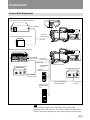
1
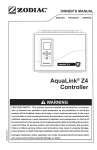
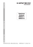
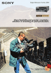
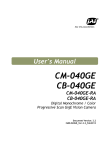
CAMERA ADAPTOR CA-570 CA-570P OPERATION MANUAL Japanese/English/German 1st Edition (Revised 1) Serial No. 15001 and Higher (UC) Serial No. 35001 and Higher (J) Serial No. 45001 and Higher (CE) WARNING English To prevent fire or shock hazard, do not expose the unit to rain or moisture. To avoid electrical shock, do not open the cabinet. Refer servicing to qualified personnel only. For the customers in the USA This equipment has been tested and found to comply with the limits for a Class A digital device, pursuant to Part 15 of the FCC Rules. These limits are designed to provide reasonable protection against harmful interference when the equipment is operated in a commercial environment. This equipment generates, uses, and can radiate radio frequency energy and, if not installed and used in accordance with the instruction manual, may cause harmful interference to radio communications. Operation of this equipment in a residential area is likely to cause harmful interference in which case the user will be required to correct the interference at his own expense. You are cautioned that any changes or modifications not expressly approved in this manual could void your authority to operate this equipment. The shielded interface cable recommended in this manual must be used with this equipment in order to comply with the limits for a digital device pursuant to Subpart B of Part 15 of FCC Rules. 1(E) Table of contens Table of Contents Overview ............................................................................................... 3(E) Location and Function of Parts and Controls .................................. 4(E) Internal Switch Settings ...................................................................... 8(E) Preparations ....................................................................................... 12(E) Attaching the CA-570/570P to a BVP-950/950P Color Video Camera .....................................................................12(E) Attaching the CA-570/570P to a BVP-550/550P Color Video Camera .....................................................................13(E) Using the Supplied Cable Holder .................................................. 14(E) Connections ........................................................................................ 15(E) Connectable Equipment ................................................................ 15(E) Power Supply ................................................................................16(E) Specifications ...................................................................................... 17(E) 2(E) Overview The CA-570/570P Camera Adaptor attaches to the BVP-950/950P or BVP-550/550P Color Video Camera to allow the connection of a CCU700A or a CCU-550 Series Camera Control Unit through a triax cable. The CA-570/570P can also be used to connect a BVW-50/50P/DVW-250/ 250P Portable VTR to the BVP-950/950P or BVP-550/550P Color Video Camera. The CA-570/570P has the following features: Component signal transmission system The CA-570/570P transmits a component signal (Y/R–Y/B–Y) through a triax cable. Low power consumption An AC/DC converter of higher efficiency than the previous model has reduced power consumption to about 11 W. Anti-electrical shock function The high-voltage supply from the camera control unit (CCU) is cut when the triax cable is not completed connected. Variety of input/output connectors The CA-570/570P is equipped with the following connectors: • DC power input/output connector • Input connector for remote-switching of return video 1, 2, 3, and 4 • Prompter signal/external sync signal input connector • RCP connector • VTR connector • INCOM connector (2) • AUDIO (LINE/MIC switch available) input connector (2) • TEST/RET video output connector • EARPHONE jack • TRACKER connector 3(E) Location and Function of Parts andof Controls Location and Function Parts and Controls 1 RET1 button/RET button and RET 2/3/4 switch CA-570P !ª PGM level control 2 TALLY lamp and TALLY switch @º ENG level control CA-570 3 PGM level controls and PROD/ ENG switches @¡ MIC LINE switch 4 INCOM level controls, PROD/ENG switches, and LEVEL/MIC switches 5 Triax connector @™ PROD level control @£ TRACKER level control 6 INCOM 1/2 connector @¢ LEVEL/MIC switch 7 VTR connector !∞ EARPHONE jack 8 REMOTE connectors !¢ TRACKER connector !£ RET CONT connector 9 DC IN connector !™ TEST OUT connector !º PROMPTER/GEN LOCK connector !¡ AUDIO IN 1/AUDIO IN 2 connectors and LINE/MIC switch and external power supply mode switch for the microphone !§ CALL button !¶ POWER switch and indicator 4(E) !• DC OUT connector 1 RET1 (return video 1) button/RET (return video) button and RET 2/3/4 switch RET1 (return video 1) button Press this button to monitor the return video1 signal from the CCU in the viewfinder or on a monitor using the TEST OUT signal . RET (return video) button Press this button to monitor the return video signal from the CCU in the viewfinder. Select the monitored signal with the RET 2/3/4 switch. RET 2/3/4 switch Selects the return video signal monitored in the viewfinder while the RET button is pressed. 2 TALLY lamp and TALLY switch When the TALLY switch is ON, the TALLY lamp lights when a red tally signal or call signal is input from the CCU. Turning S200-1 on the AU-251 board to ON mixes and outputs the battery alarm signal to the TALLY lamp. 3 PGM (program) level controls (for the CA-570) Adjusts the audio volume of the program. Note PGM level controls are provided for both intercom 1 and 2. 4 INCOM (intercom) level controls, PROD/ENG (producer/engineer) switches, and LEVEL MIC (intercom level/microphone) switches (for the CA-570) INCOM (intercom) level controls Adjusts the audio volume of the intercom. PROD/ENG (producer/engineer) switches Switches the intercom line. PROD: Selects the producer’s line ENG: Selects the engineer’s line LEVEL/MIC (intercom level/microphone) switches The LEVEL and MIC switch settings specify the following functions: REAR/ON: Turns on the intercom microphone. Adjust the intercom reception level with the INCOM control. REAR/OFF: Turns off the intercom microphone. Turn the intercom microphone on and off using the control on the external equipment connected to the RET CONT connector. Adjust the intercom reception level with the INCOM control. FRONT/OFF: Turns off the intercom microphone. Turn the intercom microphone on and off using the control on the external equipment connected to the RET CONT connector. Use the control on the camcorder to adjust the intercom reception level. Note INCOM level controls and LEVEL/MIC switches and PROD/ENG switches are provided for both intercom 1 and 2. 5 Triax connector Connects a CCU-700A/700AP or CCU-550/550P Series Camera Control Unit through a triax cable. 6 INCOM (intercom) 1/2 connectors Connects headphones to enable the reception of program/intercom audio and transmission of intercom audio. Set the MIC switch on the AU-237 board to “CM” when using a carbon-type headphone, and set it to “DYN” when using a dynamic microphone. The INCOM 1 connector can be used for communications even though the power to the camera is turned off on the CCU-700A/700AP or CCU-550/ 550P. 7 VTR connector (26-pin) Inputs and outputs video signals, audio signals, control signals, and the power supply. Connects with the CAMERA connector on a VTR or AC adaptor. Note The VTR connector cannot be used when a CCU is connected. 8 REMOTE connector (8-pin) Connects an RCP-700 Series or RM-B150 Remote Control Unit. Connection must be made with a cable of 150 feet (50 meters) or less in length. Note • The REMOTE connector cannot be used when a CCU is connected. • When connecting the RM-B150, use the cable supplied with the RM-B150. 5(E) Location and Function of Parts and Controls 9 DC IN (direct current input) connector (4-pin) Connects an AC adapter or battery case. Supplies power to the CA-570/570P when the POWER switch is set to EXT. !∞ EARPHONE jack (mini-jack) Connects an earphone for monitoring the audio from the VTR, the intercom, or the program. Select the audio source with the switch S1 on the MB-783 board. !º PROMPTER/GEN LOCK (prompter signal input and output/external sync signal input) connector (BNC type) Inputs an external sync signal or inputs and outputs a prompter video signal. Select the respective function with the PROMPTER/GENLOCK switch on the internal MD-119 board. The connector is factory set for PROMPT. !§ CALL button Use this button to call the CCU or MSU operator. When this button is pressed, the red tally lamps in the viewfinder and on the camera control unit (CCU) or master setup unit (MSU) light up. !¡ AUDIO IN 1/AUDIO IN 2 (audio input) connectors (XLR type, 3-pin) and LINE/MIC (line input/microphone) switch Inputs external audio signals. Set the LINE/MIC switch according to the input signal type. The following power supply settings can be specified for the external microphone: •: +12V is supplied to the external microphone (when the S800 switch on the AU-251 biard is set to ON). OFF: No power is supplied to the external microphone. +48V: +48V is supplied to the external microphone. (when the S700 switch on the AU-251 board is set to ON). !™ TEST OUT (test video output) connector (BNC type) Outputs return video signals, playback video signals, VBS signal, or monitor output signals. Normally outputs return video signals when a CCU is connected, and playback video signals when a VTR is connected. Note Select the output signal with switch S100 on the AU251 board. !£ RET CONT (return control) connector (6-pin) Inputs the control signal for selecting the return video and for turning the intercom microphone on and off. !¢ TRACKER connector (10-pin) Use for communications with a tracker and intercom 1 and 2 communications. Also outputs the up tally and program audio signals. The maximam output current output from this connector is 500 mA. 6(E) !¶ POWER switch Selects the power supply. u CCU: Power is supplied from the CCU. ¬ (standby): Standby mode 1 EXT: Power is supplied from the VTR or EXT DC IN connector. !• DC OUT (direct current output) connector (4pin) Outputs a direct current of 10.5 V to 17 V at a maximum rated current output of 500 mA. Connecting equipment with a power consumption greater than the maximum rating will activate the protection circuit, cutting off the current flow. !ª PGM (program) level control (for the CA-570P) Adjusts the audio volume of the program. @º ENG (engineer) level control (for the CA-570P) Adjusts the audio volume of the engineer. @¡ MIC LINE switch (for the CA-570P) PROD: Selects the producer’s line. OFF: Turns off the microphone. ENG: Selects the engineer’s line. @™ PROD (engineer) level control (for the CA-570P) Adjusts the audio volume of the producer. @£ TRACKER (engineer) level control (for the CA570P) Adjusts the audio volume of the tracker. @¢ LEVEL/MIC (intercom level/microphone) switch (for the CA-570P) The LEVEL and MIC switch settings specify the following functions: REAR/ON: Turns on the intercom microphone. Adjust the intercom reception level with the PGM level control, ENG level control, PROD level control, or TRAKER level control. REAR/OFF: Turns off the intercom microphone. Turn the intercom microphone on and off using the control on the external equipment connected to the RET CONT connector. Adjust the intercom reception level with the PGM level control, ENG level control, PROD level control, or TRAKER level control. FRONT/OFF: Turns off the intercom microphone. Turn the intercom microphone on and off using the control on the external equipment connected to the RET CONT connector. Use the control on the camcorder to adjust the intercom reception level. 7(E) Internal Swicth SettingsSettings Internal Switch CA-570/570P MD TF AU AU 1 PROMPTER/GENLOCK switch PROMPTER INTERCOM 2 GENLOCK CM DYN GAIN + 0 – 2 INTERCOM and GAIN switches INTERCOM 1 CM DYN GAIN Unscrew the four screws. CA-570/570P + 0 – Switch on the MB-783 board A CN10 B CN11 CN25 C D 3 Switch S1 S1 4 3 2 E 1 Unscrew the four screw 1 PROMPTER/GENLOCK (prompter signal input and output/external sync signal input) switch (MD-119 board) Selects the PROMPT/GENLOCK connector function. PROMPTER: Inputs and outputs a prompter signal (factory setting). GENLOCK: Inputs an external sync signal. 2 INTERCOM and GAIN switches (AU-237 board) Set these switches to specify the type of microphone connected to the INCOM 1 and INCOM 2 connectors and their respective gain. INTERCOM 1/2 switches CM: carbon microphone (factory setting) DYN: dynamic microphone 8(E) GAIN 1/2 switches +: Raises the gain 6 dB above standard gain 0: Standard gain –: Lowers the gain 6 dB below standard gain 3 Switch S1 on the MB-783 board Specifies the type of audio signal output from the EARPHONE jack. • S1-1: Set to ON to output the program audio signal. • S1-2: Set to ON to output the audio signal of intercom 1. • S1-3: Set to ON to output the audio signal of intercom 2. • S1-4: Set to ON to output the VTR playback audio signal. All switches are factory set to OFF, except S1-1. Switch on the DM-116 board A LV3 RV3 FL4 LV4 RV4 CN5 B TP4 E1 RV2 E2 TP5 4 Switch S1 CN4 C FL5 5 Switch S4 S4 FL3 S1 CN3 D FL2 FL1 E LV2 RV1 LV1 F CN2 TP3 G 4 4 Switch S1 on the DM-116 board Selects the PROMPT/GENLOCK connector function. PROMPTER: Inputs and outputs a prompter signal (factory setting). GENLOCK: Inputs an external sync signal. Note Swicth S1 on the DM-116 board is used for factory inspection use only. The PROMPTER/GENLOCK connector function is normally specified using the PROMPTER/GENLOCK switch on the MD-119 board. 5 Switch S4 on the DM-116 board Selects the direction of the prompter signal flow between the CCU and CAM. CCU→CAM: The video signal from the CCU is output from the PROMPTER/GEN LOCK connector. CAM→CCU: The signal input to the PROMPT/ GEN LOCK connector is output to the CCU. 3 2 1 6 S3 switch on the AU-237 board Specifies whether the incom audio output from INCOM 2 connector and the program audio are mixed or not. IND: No mixing (factory setting for NTSC) MIX: Mix mode 2 (set by switch S5) (factory setting for PAL) 7 Switch S4 on the AU-237 board When this switch is set to ON, the program audio is mixed with the intercom audio. The factory setting is OFF. 8 Switch S2 on the AU-237 board Specifies whether the incom audio output from INCOM 2 connector and the program audio are mixed or not. IND: No mixing (factory setting for NTSC) MIX: Mix mode 1 (set by switch S4) (factory setting for PAL) 9 Switch S302 on the AU-237 board Sets the INCOM 2 connector to either RTS mode or NORMAL mode. The factory setting is NORMAL mode. 0 Switch S411 on the AU-237 board Sets the talk level through the TRACKER connector. 0 dB: Standard level –20 dB: Decreases the talk level by 20 dB. (Select this setting when the input level is too high.) 9(E) Internal Swicth Settings Switch on the AU-237 board 4 3 2 1 E451 A 6 Switch S3 S3 S301 B !£ Switch S5 S5 7 Switch S4 S4 S2 S1 S362 C E1 CN1 RV302 8 Switch S2 E301 S363 TP301 RV301 9 Switch S302 S302 RV111 D RV112 !™ Switch S111 TP111 S182 S111 0 Switch S411 S411 E RV411 S183 E111 S181 !¡ Switch S181 F !¡ Switch S181 on the AU-237 board When the dynamic microphone used for the incom headset is unbalanced, this switch connects the MIC pin Y to ground (GND) to prevent noise. The factory setting is OFF. S181-1: Connects the MIC pin Y of Incom 1 to ground. S181-2: Connects the MIC pin Y of Incom 2 to ground. !™ Switch S111 on the AU-237 board Sets the INCOM 1 connector to either RTS mode or NORMAL mode. The factory setting is NORMAL mode. !£ Switch S5 on the AU-237 board When this switch is set to ON, the intercom audio is mixed with the program audio. The factory setting is OFF. !¢ Switch S800 on the AU-251 board Turns the power supply (12 V) to the external microphone on and off. No power is supplied if the MIC power switch on the rear panel is set to OFF or to +48V. The factory setting is OFF. !∞ Switch S600 on the AU-251 board Specifies input of the audio input signal from the MIC1 connector on the camcorder or the AUDIO IN 1 connector on the CA-570/570P. C: Input from the MIC 1 connector on the camcorder. CA: Input from the AUDIO IN 1 connector on the CA-570/570P. 10(E) !§ Switch S351 on the AU-251 board Set to ON to monitor the microphone input on a headset. The factory setting is OFF. !¶ Switch S700 on the AU-251 board Turns the power supply (48 V) to the external microphone on and off. !• Switch S200 on the AU-251 board • S200-1: When S200-1 is set to ON, the battery alarm signal is mixed with the tally lamp signal. This switch is factory set to OFF. In this position, the indicator in the viewfinder is unaffected. • S200-2: When a CCU is connected to the CA-570/ 570P, this switch specifies whether power is supplied from the REMOTE connector or not. ON: When a CCU is connected, the power is automatically turned off. When the camera is used as a stand-alone unit, the power is turned on (factory setting). OFF: The power is supplied from the REMOTE connector. Switch on the AU-251 board 4 3 2 1 !∞ Switch S600 A S600 S800 !¢ Switch S800 !§ Switch S351 S351 B CN1 C !¶ Switch S700 S700 D S200 !• Switch S200 RV220 E S100 !ª Switch S100 RV100 F !ª Switch S100 on the AU-251 board Selects the signal output from the TEST OUT connector. • S100-1: Disables automatic switching between the playback video signal and the return video signal. ON: Outputs the playback video signal. OFF: Outputs the return video signal when a CCU is attached; outputs the playback video signal when a VTR is attached. The factory setting is OFF. • S100-2: Specifies output of the VBS signal from the camera or the return/playback video signal. ON: Outputs the VBS signal from the camera. OFF: Outputs the return or playback video signal. The factory setting is OFF. • S100-3: Selects whether the control signal from the RET CONT connector is received or not. ON: Outputs the return video signal only for an L return control signal. OFF: Outputs the return video signal only when a CCU is connected. • S100-4: Selects either a VBS video signal output or monitor signal output. ON: Outputs the monitor signal. OFF: Outputs the VBS signal. The various combinations of switch S100 settings and their corresponding video output signal are as follows: S100-1 S100-2 S100-3 S100-4 RET Video output CONT signal OFF OFF — — — Return video (when a CCU is connected) Playback video (when a VTR is connected) ON — OFF ON — — — Playback video OFF OFF — VBS video — ON ON OFF — Monitor video OFF ON OFF ON L Return video (when a CCU is connected) L Playback video (when a VTR is connected) H VBS video L Return video (when a CCU is connected) L Playback video (when a VTR is connected) H Monitor video OFF ON ON ON 11(E) Preparations Preparations Attaching the CA-570/570P to a BVP-950/950P Color Video Camera When you attach the CA-570/570P to a BVP-950/950P Color Video Camera as shown below, the 68-pin connectors on both units are automatically connected. 1 Attach the CA-570/570P to the rear of the BVP-950/950P. Hook the upper part, then push the lower part in until it snaps into place. 2 Tighten the screw with a screwdriver. Tighten the screw. Removing a Camera Adaptor Loosen the screw on the video camera, then push it. 12(E) Attaching the CA-570/570P to a BVP-550/550P Color Video Camera When you attach the CA-570/570P to a BVP-550/550P Color Video Camera as shown below, the 68-pin connectors on both units are automatically connected. 1 Attach the CA-570/570P to the rear of the BVP-550/550P. Hook the upper part, then push the lower part in until it snaps into place. 2 Tighten the screw with a coin. Tighten the screw. Removing a Camera Adaptor Loosen the screw on the video camera until it stops, then remove the camera adaptor while pushing the screw. Loosen the screw on the video camera until it stops, then push it. 13(E) Preparations Using the Supplied Cable Holder 1 Attach the cable holder with the supplied two M3×6 screws. M3×6 screws (supplied) Cable holder 2 Fasten the cable clamp around the cable. cable Removing the cable clamp pull lift to release 14(E) Connections Connectable Equipment BVF-55/55CE 5-inch Viewfinder CCU-700A/700AP Series Camera Control Unit To the CAMERA connector To the triax cable connector CCU-550/550P Series Camera Control Unit Triax cable 1 u BVW-50/50P/DVW-250/250P Portable VTR To the CAMERA connector (26-pin) To the VTR connector (26-pin) Camera cable To the DC IN connector To the REMOTE connector AC-550/550CE AC Adaptor RM-B150 Remote Control Unit AC-550/550CE AC Adaptor To the CAMERA connector (14-pin) DC cord (supplied with the AC-550/550CE) To the DC OUT connector RCP-700 series Remote Control Unit 1 7000 -3 C 2 • •••• •• •• •• ••••••• CL Note When a Camera Control Unit is connected, do not connect other equipment to the VTR connector. If a Camera Control Unit and portable VTR are connected simultaneously, the camera will not operate normally. 15(E) Connections Power Supply When a Camera Control Unit is connected When the POWER switch is set to u CCU, power is supplied from the CCU. To supply a power from the DC connector Set the POWER swicth to 1 EXT. When a VTR is connected When the POWER switch is set to 1 EXT, Power is supplied from the VTR. When the CA-570/570P is attached to the VTR and power is supplied from the DC IN connector, external power supply is automatically selected. Note Due to the large power consumption of the BVF-55/55CE viewfinder, the viewfinder cannot be used when power is being supplied from a portable VTR. 16(E) Specifications General Optional accessories Power consumption 11 W Operating temperature –20°C to +45°C (–4°F to +113°F) Storage temperature –20°C to +50°C (–4°F to +122°F) Dimensions 115 × 212 × 195 mm (w/h/d) (45/8 × 83/8 × 73/4 inches) Mass 2.7 kg (5 lb 15 oz) CAC-6 Return Video Selector BVF-55/55CE Viewfinder RM-B150 Remote Control Unit Design and specifications are subject to change without notice. Input/output connectors MIC IN (2ch) DC IN DC OUT GEN LOCK IN TEST OUT RET CONT EARPHONE CAMERA I/F VTR CCU INCOM (2ch) RCP Tracker XLR type 3-pin, Female, 600 ohms, balanced XLR type, 4-pin, DC 10.5 to 17 V 4-pin, DC 10.5 to 17V, Max. 500 mA BNC type, 1Vp-p, 75 ohms BNC type, 1Vp-p, 75 ohms 6-pin Mini-jack, 8 ohms 68-pin CCZ type, 26-pin Triax XLR type, 5-pin, Female 8-pin 10-pin Supplied accessories Carrying belt (1) Cable holder (2) M3 × 6 screws (4) Operation manual (1) Maintenance manual (1) 17(E) The material contained in this manual consists of information that is the property of Sony Corporation and is intended solely for use by the purchasers of the equipment described in this manual. Sony Corporation expressly prohibits the duplication of any portion of this manual or the use thereof for any purpose other than the operation or maintenance of the equipment described in this manual without the express written permission of Sony Corporation. Le matériel contenu dans ce manuel consiste en informations qui sont la propriété de Sony Corporation et sont destinées exclusivement à l’usage des acquéreurs de l’équipement décrit dans ce manuel. Sony Corporation interdit formellement la copie de quelque partie que ce soit de ce manuel ou son emploi pour tout autre but que des opérations ou entretiens de l’équipement à moins d’une permission écrite de Sony Corporation. Das in dieser Anleitung enthaltene Material besteht aus Informationen, die Eigentum der Sony Corporation sind, und ausschließlich zum Gebrauch durch den Käufer der in dieser Anleitung beschriebenen Ausrüstung bestimmt sind. Die Sony Corporation untersagt ausdrücklich die Vervielfältigung jeglicher Teile dieser Anleitung oder den Gebrauch derselben für irgendeinen anderen Zweck als die Bedienung oder Wartung der in dieser Anleitung beschriebenen Ausrüstung ohne ausdrückliche schriftliche Erlaubnis der Sony Corporation. CA-570/570P (J/UC/CE) 3-861-962-02 (2) Sony Corporation B & P Company 2000.01.08 1998