1
Trinitron
Operating
Instructions
KV-27S26
KV-27S36
KV-27V26
KV-27V36
KV-29RS26
KV-29RS26C
KV-29V36C
KV-29V66M
KV-29V76M
© 1997 by Sony Corporation
Color TV
KV-32S26
KV-32S36
KV-32TW26
KV-32V26
KV-32V36
KV-34RS26C
KV-34V36C
KV-35S26
KV-35S36
KV-35V36
KV-35V76
KV-37RS26
KV-37V36M
CAUTION
WARNING
To prevent
fire
or shock
hazard,
do not expose
the TV
When
with
to rain or moisture.
using TV games,
your
TV. keep
functions
at low
pattern
computers,
settings.
brightness
for
or contrast
Iogos
imprints
ATI'ENTION
they
R_SQUEDE C_OC ELECTRIQUE,
NE PA$ OUVRIR
are not
are the
Note
PRECAUClON
onto
covered
periods
of time
the image
These
by your
types
warranty
at
can be
Note
on
because
Vision
cleaning
the
with
w;th
that
This
which
equipment
off
correct
interf_.rence
the
following
will
not
occur
If this equipment
does
to radio or television
can be determined
and
cause harmful
However,
interference
installation.
interference
reception,
on, the
user
by turning
is encouraged
by one
or more
the
to try
to
of the
measures:
•
Reorient
or rel.}cate
•
increase
receiver.
the
•
Connect
the ecuipment
different
TV
installation.
:he instructions,
may
radio communications.
is no guarantee
in a particular
cause harmful
This television receiver provides display of television
closed captioning in accordance with §15.119 of the
FCC rules.
RIESGO DE CHOQUE ELECTRICO
NOABRIR
in a residential
generates,
uses, and can radiate
radio
energy
and, if not installed
and used in
accordance
inteference
there
of
of misuse.
on Caption
interference
equipment
frequency
the screen. Continuously
can cause the imprint
of
the TV screen,
result
products
contrast
(non-moving)
long
setting,
permanently
imprinted
onto
watching
the same program
station
and
If a fixed
is left on the screen
a high
and similar
the brightness
the
receiving
separation
from
that
antennas.
between
into
the
equipment
an outlet
to which
the
and
on a circuit
receiver
is
connected.
CAUTION:
TO REDUCE
THE ItlSK OF ELECTRIC
DO NOT REMOVE
NO
O)VER
USER-SERVICEABLE
REFER I;ERVICING
TO QUALIFIED
Clean the TV with a soft dry cloth. Never use strong
solvents
such as thinner
or benzine,
which might
SHOCK,
(OR BACKI.
damage
the finish
of the
CATV
system
•
'the
presence
SERVICE
is intended
PERSONNEL.
Note
to alert
of uninsulated
the
user to
"dangerous
'voltage"
within
the product's
enclosure
that
may be of sufficient
magnitude
to constitute
a risk of electric
to
shock
provides
guidelines
symbol
You
installer
specifies
connected
to the
close to the
is intended
of important
maintenance
(servicing)
accompanying
proper
that
the cable
grounding
point
grounding
of cable
ground
system
entry
and,
f_r
or an experienced
radio/TV
help.
shall
of the
to alert
the user to
operating
instructions
and
in the
the appliance.
viewing
of programs
transmitted
general
television
by cable
public
may
broadcasterlcable
receiver
be
broadcast
companies
require
as
company
CAUTION
NOTIFICATION
TO PREVEHT ELECTRIC SHOCK, DO NOT USE THIS
This equipment
POLARIZED AC PLUG WITH AN EXTENSION CORD,
RECEPTACLE, OR OTHER OUTLET UNLESS THE BLADES CAN
with
the
Part
15 of the FCC Rules.
BE FULLY INSERTED TO PREVENT BLADE EXPOSURE,
provide
limits
has been
for the
and/or
tested
reasonable
These
protection
from
program
device
limits
against
changes
or
approved
authority
in this
to operate
this
to comply
pursuant
are designed
is ':or the
to
to
remote
conl:rol
RM-Y136A/
Y137A.
KV-;!7SZ6,
27S36,
29R_26C,
29V36C,
34V:36C,
37V36M
the
owner.
harmful
could
32S36,
use of the
and found
for a Class B digital
v¢,id your
MODELS:
private
on UHF or VHF or
authorization
any
manual
This document
building,
than
ad that
not expressly
equipment.
as practical.
for other
are caution
modifications
in
to persons.
_:he presence
literature
for
particular,
Use of this
This
the dealer
PARTS INSIDE.
This reminder
is provided
to call the CATV system
installer's
attention
to Article 820-40 of the NEC that
This symbol
Consult
technician
cabinet.
32TW26,
35S26,
27V26,
27V36,
29V66M,
32V26,
35S36,
29RS26,
29V76M,
32V36,
35V36,
32S26,
34RS26C,
35V76,
37RS26,
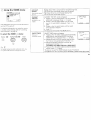
Remote
Control
hi the instructions that follow, we will refer
tc_the buttons on llour remote control.
Keep this flap un_dded and look to this page
fcr reference.
SYSTEM
(page
Names
15)
DISPLAY
SLEEP
JUMP
TV/DBS
(page 20)
RESET
(page 19)
VOL +/CODE SET
(page
24)
of the buttons
presenLe(i in different
available functions.
TV (FUNCTION)
PIP (page 16)
TV/VIDEO
ANT (page 3 and 15)
0-9
_
to know
control
the
buttons
on the
TV (POWER)
OFF
9 and
Getting
remote
MUTING
.........
Green ...............
MTS (page
buttons
(page
12 and
are
the
Press to select the componenL
you want to control; e.g.
VTR (VCR), DBS (Direct
Broadcast Satellite)/CABLEo
or T_
Buttons relevant to power
operations,
like turning the
TV, DBS (Direct Broadcast
Satellite)/CABLE,
or VTR
(VCR) on or off.
20)/GUIDE
Select
control
colors to represent
Button color
TransFarent
buttons
ENTER
on the remote
18)
MENU
Label co or
White ...............
TV/VTR (VCR)/DBS (Direct
Broadcast Satellite) / CABLE
Yellow ...............
Blue .................
opera tion buttons.
PIP operation buttons.
DBS (Direct Broadcast
Green ................
Satellite) operation buttons.
S-Link operation buttons.
For a detailed
"Watchi:zg
explanatio_t
rite I3/"
on page
of most
14.
buttons,
see
Table
41elcome!
........................................
_recautions
Jsing
of Contents
......................................
This Manual
-.onnectfng
...........................
and Installing
1
I
I
the TV
::onnector Types ..........................................
2
daking C onnections ....................................
Conno:ting directly to cable
or m_antenna ........................................
Cable or antenna ......................................
Cable and antenna ...................................
2
Conno__ng a cable box ............................
Cable box and cable .................................
3
3
2
3
3
Conne:ting an antenna/cable TV system
with a VCR ..........................................
4
Corme:ting to an S Video equipped
VCP .....................................................
Conne:_g
bOX
a DBS receiver ...................... 6
a DBS receiver and a VCR .... 6
an audio system ................... 7
an AV receiver ...................... 7
Operating
vicreo equipment
Setting the manu:!acturer's code ................... 24
Operating
a cable box or DBS receiver
Basic Set Up
Inserting batteries ......................................... 12
the remote ..............................26
Troubleshooting
27
...........................
Using the remote control Select buttons ..... 12
Adjusting sliders ..........................................
12
Chl Line Help/h_tructions
12
Using your
New
..........................
Setting up the TV automatically
.................. 13
Watd_ing two programs at one
time -- PIP .........................................
Adjusting
Specification,.:
Index
................................
28
..............................................
31
TV
14
Owner's
The
model
of the
Record
and
serial numbers
TV, below
the
Sony
also on the TV box (white
16
5
Conne:'ting to an S Video equipped VCR
with a cable box ................................. 5
Connecting
Connecting
Connecting
Connecting
Using the SET UP menu .............................22
8
9
9
10
11
Progr_g
Watching the TV ..........................................
4
a VCR amd TV with a cable
.......................................................
Connecting two VCRs for tape editing
using MONITOR OUT .......................
Using the S-Link function ........................
Connecting a camcorder ..........................
Installing the glass door .........................
Adjusting the shelf .................................
your SET UP (menus)
Learning menu selection .............................. 18
Using the VIDEO menu ............................... 19
Using the AUDIO menu .............................. 20
Using the TIMERmenu ............................... 21
in the spaces
provided
you
yoar
call upon
Model
No.
Serial No.
!;ony
KV-
are located
logo,
label).
below.
dealer
at the rear
on the sticker,
Record these
Refer
to them
regarding
and
numbers
whenever
this product.
Precautions
Welcome!
Thank you for purchasing the Sony Trinitron ®
Color TV. This manual is written for the models
listed bellow. Before reading, check the model
number on the rear of your TV.
Safety
• Operate the TV only on 120 V AC
(except KV-29RS26C, 29V36C, 34RS26C,
34V36C).
Model KV-27S26 is used for illustration
purpose:s. The screens displayed are for model
KV-35V36. Differences in operation features are
indicated in the text; for example, "KV-27S26
only".
.2
Model
Number
_
_
_
_
_
Operate the TV only on 220 V AC
(KV-29RS26C, 29V36C, 34RS26C, 34V 36C
only).
The plug is designed, for safety purposes,
to fit in the wall outlet only one way. If
you are unable to insert the plug full_ into
the outlet, contact your dealer
(except KV-29RS26C, 29V36C, 34RS26C,
34V36C).
/
_ ._
_E
,
KV-27S26
KV-2?V26
!_l:_ZZ3__.ik:;
o
KV-29RS26
• If any liquid or solid object should fall inside
the cabinet, unplug the TV immediatebT and
have it checked by qualified personnel
before operating it further.
•
KV-29V76_
KV29V36C
i
KV 32536
If you will not be using the TV for several
days, disconnect power by pulling the
plug itself. Never pull on the cord.
•
For details concerning
KV-32V26
supplied
KV-34RS26C
1_,.3_Kt
@(:Z:
: c
KV35526
•
•
KV35V36
•
•
•
•
"KV'3_V_'
KV 37RS26_;'
Using
safety precautions,
leaflet "IMPORTANT
see the
SAFEG UARD'_;'.
Installing
• To prevent internal heat build-up, do not
block the ventilation
openings.
• Do not install the TV in a hot or hum: d
place, or in a place subject to excessi_.e
dust or mechanical vibration.
This Manual
This manual is divided into four major
sections. We recommend
that you carefully
review th _ contents of each section in the
order pro_,ided to ensure
unders:and
the operation
that you fully
of your new TV.
1 Connecting and Installing the IV.
This section will guide you through your
initial _;et up. It will slnow you how to
connect your new components,
connect to
your antenna or cable, and connect any
accessories.
Basic Set Up.
This section will teach you the basic skills
needed to operate your new TV. It will
show you how to operate special functior_s
of the ::emote control.
3 Using your New TV
This s.:_ction will show you how to begin
using '!our new TV. It will show you how
to use the AUTO SET UP feature, and how
to use your remote control's features.
4 Adjusting your Set Up (menus).
This section will teaclh you how to access
or,,-screen menus and adjust your TV's
settings.
Instr;_ctio_::in this manual arc written for the remote
contrd. Si_i_:ilar controlsmay befound on the TV console.
II
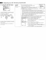
connecting
Connector
and Installing
the TV
Making
Types
C
Connections
_'OUmay J!ind it necessary to use some of the
:ollowing connector types during set up.
For best picture quality, a cable TV system or
outdoor antenna is recommended.
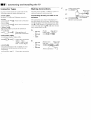
"oaxial (:able
;tandard TV Cable and Antenna connector
Connecting
antenna
'lug Type
_t__,
;crew-on
_@
Press onto connection
Type
_
_
Screw
; Video Cable
tigh quaLty Video connector
icture quality
onto
connection
_.udio/Video
2onventional
::::=::_:_
--_ _)
Cable
Audio/Video
_
@
directly
to cable
Press onto connection
Yellow - Video
White - Audio (Left)
Red - Audio (Right)
;-Link Cable
;ony Link. connector (only available on Sony
_roducts) for simultanc.ous control of your
omponents
_2Z_=,
--* @
Press onto connection
__i_._=
UHF: --
The connection you choose will depend c,n
the cable found in your home. Newer homes
will be equipped with standard coaxial cable
(see A); older homes will probably have 300ohm twin lead cable (see B); still other homes
may contain both (see C).
A
cable
coaxial
cable
(Rear of TV)
i_
or an
for enhanced
Align guides and
press onto connection
VHF
and
•
__,,
75-ohm
•
•
VHF only
or
VHF/UHF
•
or
CaNe
•
VHF only
•
UHF only
•
VHF/UHF
75-ohm
coaxial
cable
--_
(Rear of TV)
VHF/UHF
""_
300-ohm
twin
lead cable
(Rear of TV)
VHF/UHF
or
Antenna
/
connector
K£"_._
"N ..,_
_..J_
300-ohm
twin
(not
lead
cable
supplied)
:able
or antenna
Connecting
,lost simple connection. Connection is made
irectly from the cable or antenna to the TV.
a cable
box
*Cable
Some pay cable TV systems use scramblec or
encoded signals that require a cabIe box* to
view all channels.
box
AUX
s.0mbl ;ZI
ch'mqels
(Rear of TV)
(Rear
(Rear of TV)
|
TO CONVERTER
of TV;
VHF/UHF
Cable
Cable
VHF/UHF
75-ohm
cable
coaxial
(not supplied)
i
! (signal)
:able and antenna
!
KV-27S36, 27V36, 29V36C, 29V76M, 32S36, 32V36,
34V36C, 35S36, 35V36, 35V76, 37V36M only
ou may find it
)llowing :set up
ot feature local
:_ceive using an
convenient to use the
if your cable provider does
channels that you are able to
antenna.
(Rear of TV)
CATV cable
(No connection
"TO
CONVERTER"
in this case)
AUX
(_
TO CONVERTER
Antenna
cable
VHF/UHF
elect Cable or ANT mode by pressing ANT on
_e remote control.
*Cable
CATV cable
(urlsc "ambled
channnels)
!
box
Note:
• If you will be controlling all channel
selection through your cable box you
should consider using the CHANNEL
feature discussed on page 22.
Cable
•
VHFIUHF
box and
For this set up, you can switch between scrambled
charmels (through your cable box), and normal
(CATV) channels by presskng ANT on your
remote cor.trol.
FIX
cable
KV-27S36, 27V36, 29V36C, 29V76M, 32S36, 32V36,
34V36C, 35S36, 35V36, 35V76, 37V36M only
Some pay cable "IV systems use scrambled or
encoded signals requiring a cable box* only for
certain channels (e.g. HBO, SHOWTIME, _,tc.).
* Your Sony remote control can be programmed
to open: te your cable box (see page 26).
Notes:
• You ca anot watch the signal through the
"AUX" input as a window picture when
using P:cmre-in-Pic_re (PIP).
• If you a::e connec_ng a cable box through
the"AUX" input and would like to switdl
betw,_n the "AUX" m_d normal (CAW) input
you should consider using fl_eCHANNEL FIX
feature discussed on page 22.
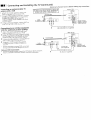
Connecting
and Installing
the TV (continued)
Disconnect
:onnecl:ing
an antenna/cable
;ystem 'with a VCR
all power
TV
I ' _Attach the coaxial connector from your
cable or antenna to IN on your VCR.
), Using AUDIO/VIDEO
connectors, connect
AUD_[O and VIDEO OUT on your VCR to
AUDIO and VIDEO IN on your TV
(Yellow-VIDEO,
White-AUDIO
Left, RedAUDIO Right).*
3 Using a coaxial connector, connect OUT on
your VCR to VHF/UHF
on your TV.
sources before making
VCR must
be connected
and
turned
on
to operate
Coaxial
,,Rear of TV)
PIP ]
(KV-27526, 27V26, 29R526, 29RS26C, 29V66M,32.;26,
32TW26, 321/26, 34R526C, 35526, 37R526 on/yL
}
I's@'l
cable
vc.
_olc _ Auo_. ,,l_Eo
aV/;_?E_
t
_--
0
,
I
....
0
--'
AUDIO-L
(white)
VIDEO (yellow)
__
Connecting
to an S Video equipped
VCR (for optimum
picture
quality)
1 Attack. the coaxial connector from your
cable or antenna to IN on your VCR.
2 Using AUDIO conr, ectors, connect AUDIO
OUT on your VCR to AUDIO IN on your TV
(Wt'dte-AUDIO Left, Red-AUDIO Right).*
3 Using a coaxial connector, connect OUT on
yourVCR to VHF/UHF
on your TV.
4 Using an S VIDEO connector, connect
S VIDEO on your VCR to S VIDEO on
your TV.
If you are connecting a monaural VCR,connect only
fl_esingle audio output to the left input on },'ourTV.
any connection:;.
I
UDIO-R
(red)
r
VMC-810S/820S
(nat
supplied)
(Rear of TV)
','JDE0 JJ
svoEo _
3
Coaxial
cable
VCR
Cable
Note on DVD Connection:
• For the best picture quality, connect the DVD player directly to the TV.
Refer to your DVD manual for detailed connection information.
4
I_ o_'_
? l,
2
YC-15V/30V
(not supplied)
RK-74A
I
(not
supplied)
AUDIO-R
AUDIO-L
S VIDEO
(red)
(white)
Disconnect
Connecting
cable box
all power
sources
before
making
any connections.
a VCR and TV with a
VCR must
(KV-27S26,
Connect the single (input) jack of the
Splitter to your incoming cable connection,
and connect the other two (output) jacks
(using coaxial cable) to IN on your cable
box and VHF/UHF
on your TV.
Using a coaxial connector, connect OUT
on yo_;.r cable box to IN on your VCR.
Using AUDIO/VIDEO
connectors,
connect AUDIO and VIDEO OUT on your
VCR to AUDIO and VIDEO IN on your
TV (Yellow-ViDEO,
White-AUDIO
Left,
Red-AUDIO
Right).
.'onnecting
to an S Video
/CR with a cable box
equipped
32TW26,
To view scrambled channels through },our
cable box, select VIDEO 1 by pressing TVi
VIDEO on the remote control.
27V26,
321/26,
and
turned
29RS26,
on to operate
29RS26C,
34RS26C,
Coaxial
35S26
29V66M,32S26,
37R526
on]/).
(Rear of TV)
PIP I
I
r VlBEO itT--i
I
cable
.'Hr 'JHr
Cable
_:_-
AUO:; OUT
....
._:,-,,_
VCR
_:_
_up,o _,'K :,_1,_: I
H
',/_----
VIDEO
(yellow)
____
VMC-810S/820S (not supplied)
Splitter
(not supplied)
for optimum
picture
quality)
I-2 Perform as described above.
I Using AUDIO connectors, connect AUDIO
OUT on your VCR to AUDIO IN on your TV
(White-.AUDIO Left, Red-AUDIO Right).
Using an S VIDEO connector, connect S VIDEO
on your VCR to S VIDEO on your TV.
lote:
be connected
Coaxial
Cable
box
(Rear
of TV)
cable
VCR
....
Cable
YC-15Vi30V
(not su 3plied)
1
RK-74A
Splitter
(not supplied)
Cable
box
(not
,supplied)
AUDIO-R
AUDIO-L
__
S VIDEO
(red)
(white)
Connecting
Connecting
a DBS (Direct
Satellite)
receiver
and Installing
Broadcast
1 Conrect the cable from }'our satellite antenna
to your DBS receiver.
2 Attach the coaxial connector from your cable or
antenna to VHFiUHF on your TV.
3 Using AUDIO/VIDEO
connectors, connect
AUDIO and VIDEO OUT on your DBS receiver
to AUDIO and VIDEO IN on your TV.
the TV (continued)
Disconnect
I
For the highest picture quality, use S VIDEO
your
instead
DB5
of
the manual
yellow
for
more information,
AUDlONIDEO
cable.
the cable from your satellite
to your DBS receiver.
sources before
(Rear
I
See
I 2
DBS receiver
making
any connections.
of TV)
SVl_ o _
VH_,LHF
!
iAUO,OOW
_-
S_TELL"_ IN
R
antenna/
cable
_,_--_-'_
J
! n
#r-C_r-_r--- AU DIO-R
_ _
Connecting
a DBS (Direct
Broadcast
Satellite)
receiver
and a VCR
1 Connect
all power
3
VMC-810S/820S
T
(not
(red)
AUDIO-L
(white)
VIDEO (yellow)
'--
supplied)
antenna
2 Attach the coaxial connector from your cable or
antenna to VHFiUHF-IN
on your VCR.
3 Using a coaxial connector, connect VHF!UHFOUT on your VCR to VHF/UHF on your TV.
4 Using AUDIO/VIDEO connectors, connect
AUD]O and VIDEO OUT on your DBS receiver to
AUDIO and VIDEO IN on your VCR.
5 Using AUDIO/VIDEO
connectors, connect
AUDIO and VIDE() OUT on your VCR to
AUDIO and VIDE() IN on your TV.
VMC-810S/820S
(not
supplied)
VCR
_
(Rear
of TV)
2 I
_HF,UHF
AUDIOOUT
VIDEO
R
DBS receiver
Note:
• To view input from the DBS or VCR, select VIDEO 1
by pressing TV/VIDEO
on the remote control.
6
AUDIO-L (white)
AUDIO-R
(red)
VIDEO(yellow)
-_
T
VM 2-810S/820S
(not: supplied)
'
:
:'
_
Disconnect
Connecting
an audio
system
For greater viewing pleasure, integrate your
home stereo into the system.
1 Using AUDIO connectors, connect AUDIO
OUT on your TV to one of the unused Line
inputs (e.g. Tape-2, etc.) on your stereo (WhiteAUDIO Left, Red-AUDIO Right).
2 Set yo_ar stereo to the chosen Line input
and refer to page 20 of this manual for
additional audio setup instructions.
Connecting
•
all power
sources
before
making
any connections.
(Rear of TV)
1
RK-74A
v7
AUDIO-L
L
i q_
AuoIO
I
;<,
(white)
(not
' L
/,_
_
R
<=_=,...>
supplied)
1
AUDIO-R (red)
_'_t
input
Vt
I_ I
!
an AV receiver
KV-27V:I6,
29V36C, 29V76M,
35V36, 35V76, 37V36M only
For greater viewing
AV receiver.
pleasure,
32V36,
34V36C,
connect your
1 Using AUDIO/VIDEO
connectors, connect
VIDE() 1 IN on your TV to Monitor AUDIO
and V] DEO OUT on your AV receiver.
AUO,O-R<ro0,
VMC-810S,8201,:oct.u
1
AUDIO-L
(white)
V' D EO (yell ow)
_
_,rr_lyl _
_
/
1
(R_,ar of KV-27V36_)
]
/_V
outputs
2 Using AUDIO/VIDEO
connectors, connect
TV OUT on your TV to TV AUDIO and
VIDE() IN on your AV receiver.
You may want to use CHANNEL FIX to fix your
FV's inpu;! to the AV recefver (VIDEO 1).
5ee CHANNEL FIX, page 22.
AUDIO-/(whi,e)--:_} 0 2
Y Av inputs
7
Connecting
and Installing
the TV (continued)
Disconnect
all power
sources before making
any connection._.
:onnecl:ing
two VCRs for tape
._diting using MONITOR OUT
KV-27V26, 27V36, 29V36C, 29V66M, 29V76M,
32V26, 32V36, 34V36C, 35V36, 35V76, 37V36M
(Rear
,4ONITOR OUT gives you the ability to use a
econd VCR to record a program being played
}y the primary VCR or to perform tape
,diting and dubbing.
[ Connect the VCR intended for playback
using t]_e setup instructions
on page 4 of
this manual.
of TV)
iN
only
VCR (for
playback)
tINE
out
VCR (for
.....
IN
....
2
Using AUDIO/VIDEO
connectors,
connec: AUDIO and VIDEO IN on your
VCR intended for recording to MONITOR
AUDIO and VIDEO OUT on your TV.
_lotes:
, Do not change the input signal while
editing through MONITOR OUT.
When connecting a single VCR to the TV;
if VCR LINE OUT is connected to TV
VIDEO IN, do not connect the TV
MONITOR OUT jacks to the VCR LINE
INPUT (see right). Doing so will cause
program interference
and other viewing
problems.
_
___
I
I
VMC-8105/8205 (not supplied)
VMC-8"
[X(RearofTV)/
Indicates
of tdgnal
direction
recording)
..................
oo,1:
0S/820S
(not
supplied)
VIDEO
AUDIO-I (yellow)
(white)
AUDIO-R (red)
Disconnect
Using
,
the
S-Link
KV-27V26, 27V36, 29V36C, 29V66M, 29V76M,
32V36, 34V36C, 35V36, 35V76, 37V36M only
making
any connections.
of TV)
_N
AUDIO-L (white)
VIDEO (yellow)
_-_
"_I_
is convenient for viewing
from your camcorder.
S VI{IEO
I
AudiolVideo
(not supplied)
Cable
2
(Front of KV-32V36, 34V36C,
35V36, 35V76, 37V36M)
VIDE,)
32V26,
i___O_UT
S-LINK
(black)
a camcorder
KV-27V26, 27V36, 29V36C, 29V66M, 29V76M,
32V36, 34V36C, 35V36, 35V76, 37V36M only
['his connection
)icture directly
before
(Rear
1 Connect your VCR using the setup
instructions on page 4 of this manual.
Z Using an S-Link connector,
connect the
S-LINI< jacks on your VCR and TV. Ensure
that both ends are seated firmly and that the
TV S-LINK connector is in the same row as
the AI2 DIO/VIDEO connectors.
,
sources
VCR
32V26,
;-Link is a Sony innovation designed to make
your Son}' components work together. It allows
you to aul:omatically switch theTV input mode
:o video v:hen you press PLAY on your Sony SLink VCR. It also allows you to turn the VCR
md TV otf at the same Lime with the SYSTEM
DFF button.
Connecting
all power
function
Ifyou have an S Video equipped camcorder,
you can use an S Video connection for
optimum
picture
2 INPUT
_
_
.
quality,
a
VtDI!O(yelI°w)_
_Jsing AUDIO/VIDEO
connectors, connect
\UDIO and VIDEO OUT on your camcorder to
\UDIO and VIDEO IN _n the frontpanel
of your
['V (Yellow-VIDEO, White-AUDIO Left, RedXUDIO Right).
_ote:
If you are connecting a monoaural camcorder, connect only
the single audio output to the left input on your TV.
AV output
___
K
"
VMC.810S/820S']
@,,,xCAUDlO-R(red)
y .;-'-'-'-'-'-'-'-'_AUDIO-L
(white)
,_,_-,,,,_ (not supplied) l
E',_,,,
',o,,
"_-:_
%-_,'.S4
_"_=/"
''/
_H
Connecting
(V-32TW26
and
and Installing
KV-35V76
only
the TV (continued)
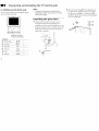
Note:
•
:ollow these instructions to install the glass
toor and adjust the shelf.
Confirm ttuat all parts are included before
beginnh_g assembly. If any parts are missing,
contact your dealer.
Installing
1
push again.
Parts List
A
Bottam hinge
_
1
B
Top hinge
_
1
C
Screw 4x4
D
Plate pad
E
F
_
4
_
1
Plate
_
1
Metal pin
_
4
glass
door
Check that the projection of the screw
through the bottom hinge A does not
interfere with the proper installation o; the
hinge to the glass door, and then insert the
hinge into the hole located at the bottom
right side of cabinet.
Push here to close.
To open,
the
C
2 Attach :he top hinge B to the right side of
the g[ass door; tighten the screws snugly,
but do not overtighten.
Attach the plate
pad D to the left side and push the plate I:
over the plate pad.
B
Pushthetopglass
doorhingeintothetop
rightbushing
andgentlyslidetheglass
doorintothebottomhinge.Adjustthe
glassdooruntillevel,andtightenthe
hingescrews.
Adjusting
the
shelf
1 Press the upper part of the temporary
shelf supports and remove the shelf.
2 Insert the metal pin shelf supports
side).
Metal
3 InserI tt-e shelf, ensuring that the pin
supporl:_ are seated in the grooves on the
botto:n _ide of the shell!.
(2 each
pin
1"1
_
Basic Set up
Inserting
batteries
Insert two size AA (R6) batteries (supplied) by
matching the + and - on the batteries to the
diagram inside the battery compartment.
Using
Select
the remote
buttons
_o_
On Line
control
Several n"enu windows will provide prompts
and instructions
to assist: you in navigating
throt, tgh the different functions. When
presented, use these to sup]dement the instructior_s
in this ma:lual.
CH
Select
Notes:
• Remove the batteries to avoid damage
from possible battery leakage whenever
you ar ticipate that the remote control will
not be used for an extended period.
• Handle the remote control with care.
Avoid dropping
it, getting it wet, or
placing it in direct sunlight, near a heater,
or where the humidity is high.
•
Your remote control can be programmed
to
operate most video equipment.
See page 24.
The supplied remote control has select
buttons which allow for movement of the onscreen selector in four directions. Pressing; on
the edge of the select buttons will cause the
selector to movL"in the selected direction.
Pressing the center of the select buttons
will activate the selected item.
Adjusting
Help/Instructions
".2E "
sliders
When menu items present a slider (,,,,_I:,_L_,,
.........or
............
_,,.,,,,,,,,.),
use the select buttons (It or I_) to adjust
the setting.
Using your
New
TV
Using the buttons
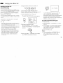
;ettincl up the TV
tutomatically
-"
SETt_p TV,'_IDEO - VOLUUE÷
1 Press POWER
the
After using EASY SETUP IF,UIDE you will still have the
option of adjusting any of the,,system settings, like erasing
channels, through the SET UP menu (page 22).
37V36M only)
ENGLISH
ESPANOL
:
:
SET UP :
:
[VOL-]
[TV/VIDEO
Press
]SET UP] to
displayc:d. If the TV receives cable TV chalmek%
CABLE is set ON automatically.
To perfolrm
•
exit.
2 (Except Canadian models)
Press CHANNEL + to select English
screens or CHANNEL - to select Spanish
screens.
- CHANNEL
PROGRAM
"ALTFO PROGRAM" appears and the TV
starts scammlg m_d presetting chalmels
automatically. When all the receivable charmels
are stor_d, the lowest numbered charmel is
[CH÷]
[CH-]
First please
connect
the antenna
The TV must beset to TV inpv:.tto executeAUTO
PROGRAM. PressAiXrI"unti.!thechanne!number appo_rs.
If your cable or antenna is connected to AUX, then
press ANT until "AUX" appears next to the channel
mmlber. (KV-27S36, 271736, 29V36C, 29V76M,
32S36, 31'.V36, 34V36C, 35S36, 35V36, 35V76,
AUTO
to turn on the TV.
AUTO
DEMO
"'_"
Pe_onn this fimction during the day, with the antenna
and/or cable properly connected, to ensure that all available
channels will bebroadcasting and receivable.
tZD U
The EASY SETUP GUIDE screen appears.
POWER
VOLUME+
po_E_
For KV-27V36, 29V36C, 29V76M, 32V36,
34V36C, 35V36, 35V76 and 37V36M, the cot troI
buttons are located on tt_e top of the TV.
'he EASY SETUP GUIDE feature does not apply
_r installations that use a cable box for all chmmel
qcction.
ips
C_AN_EL÷
olJ
he EASY SETUP GUIDE feature wqll allow you
set the on-screen language and set all receivable
hannels. The EASY SETUP GUIDE screen will
ppear evelT time you turn on the TV until you
erform AUTO PROGRAM.
b set up the TV manually,
refer to "Using
ET UP mer!!" on page 2.2.
on the front of the TV:
AU¥O SET UP again
Press SET UP.
PrL_s CHANNEL + or Ct4ANNELlanguage.
to select a
Press Volume - to restore factory settings
("CONTINUE
TO AUTO PROGRAM?"
will appear on the screen. Press CH+ to
execute or CH- to exit).
+
• Press SET UP to exit.
Note:
•
3
Press VOLUME - to continue or TV!\qDEO
for a DEMO of hmcfions and menus.
When ,,ou perform AUTO PROGRAM,
your CHANNEL FIX, TIMER, and
CHANNEL BLOCK settings will be
erased.
1 "|
Jill
using
Watching
the
All of the TV features
your
New
TV (continued)
TV
can be accessed
via the
re'mote control. The following chart will
explain the function of the buttons found on
,our remote control
REFER TO THE
ILLUSTRA TION OF THE
REMOTE CONTROL ON THE
INSIDE FRONT COVER OF
THIS MANUAL AS YOU
REVIEW THIS CHART
TV (FUNCTION)
Activates the remote control for use with the TV.
TV POWER
Turns the TV on and off. If "VIDEO" appears on the screen, press TV/VIDEO
or ANT so that a channel number appears.
('_.
(_"l
Use for direct channel selection. Press 0-9 to select a channel (for example,
to select channel 10, press 1 and 0), the channel will change after 2 seconds,
or you can press ENTER for immediate selection.
CH +/-
Press to scan through the channels (+ up or - down).
VOL +/-
Press to adjust the volume (+ up or - down).
JUMP
Press to alternate or jump back and forth between two channels. You can only
jump between the last two channels that have been selected with the 0-9 keys.
MUTING
Press to mute the sound ("MUTING" will appear on the screen). Press again
or press VOL + to restore sound.
FREEZE-
Press to freeze the window picture while in PIP mode. If you are not in PIP
mode, pressing FREEZE will cause the main picture to freeze into a window
picture. Great for copying down phone numbers, addresses, recipes, etc.
SLEEP
•DISPLAY
TV/VIDEO
ANT
(AUX input)
Press
repeatedly
until
theTVdisplays
theapproximate
timeinminutes
(30,60,
or90)thatyouwant
theTVtoremain
onbefore
shutting
offautomatically.
Cancel
bypressing
until
"SLEEP
OFF"
appears.
Press
repeatedly
tostepthrough
available
displays:
Status
Channel
number,
current
time,
channel
caption
(ifset),
and
MTS
mode
(ifSAP
is
selected)
aredisplayed.
SAP
indication
disappears
after
three
seconds.
XDS
XDS(Extended
Data
Service)
shows
anetwork
name,
program
name,
program
type,
program
length,
callletters,
andtimeoftheshow
ifthe
broadcaster
olfers
thisservice.
Caption
Vision
Caption
Vision
willbedisplayed
onthescreen
ifthebroadcaster
offers
this
service.
(seeright)
Tocancel
thedisplay,
press
DISPLAY
repeatedly
until"DISPLAY
OFF"
appears.
"DISPLAY
OFF"
disappears
after
three
seconds.
Press
repeatedly
tostepthrough
available
video
inputs:
TV,Video
1andVideo
2(KV-27S26,
27S36,
29RS26,
29RS260,
32S26,
32S36,
32TW26,
34RS26C,
35S26,
35S36,
37RS26
only)
TV,Video1,Video
2andVideo3(KV-27V26,
27V36,
29V36C,
29V66M,
29V76M,
32V26,
32V36,
34V36C,
35V36,
35V76,
37V36M
only)
Press
tochange
theVHF!UHF
input
totheAUX
input
(KV-27S36,
27V36,
29V360, 29V761vl, 32S36, 32V36, 34V36C, 35S36, 35V36, 35V76, 37V36M only)
For detailed connection information, see "Cable box and cable" or "Cable and
antenna" on page 3.
SYSTEM OFF
MTStG U ID E
KV-27V26, 27V36, 29V36C, 29V66M, 29V76M, 32V26, 32V36, 34V36C,
35V36, 35V76, 37V36M only.
Press to turn off the TV and all other equipment connected with S-Link and
return the TV input to either antenna or AUX, whichever was last used.
CAPTION
CAPTION
VISION
_.lz] 1
VISION
_Tt
i_
1 TEXT
I_t
2
TEXT 4
TEXT 3
_MENU
Some programs are broadcast with Caption
Vision. Io display Caption Vision, select CC1,
CC2, CC3, CC4, TEXT1, TEXT2, TEXT3, or
TEXT4 from the menu, then press DISPLAY
until Caption Vision is displayed.
CC1, CC2, CC3, or CC4 shows you a caption,
that is, a printed version of the dialogue or
sound effects of a program. (]he mode should
be set to CO1 for most programs) TEXT1,
TEXr2, TEXT3, or TEXT4 shows you text, that
is, inf3rmation presented using either half or the
whole; screen. It is not usually related to the
program•
Notes:
• Poor reception of TV programs can cause
err3rs in Caption Vision and XDS.
Captions may appear with a white box or
other errors instead of intended text•
• XCS, Caption Vision, and the status display
cannot be used at the same time.
Press this button to cycle through the Multi-channel TV Sound (MTS) options. (page 20)
15
Using
Natching
two
your
New
programs
TV (continued)
at one time
m PIP
The sound of the main
picture is received,
7he Picture-in-Picture
(PIP) feature allows you
o view two channels simultaneously,
one in
he full size "main" picture and one in a smaller
'window" picture. This means that two
eparate tuners must be available to provide
he two signals.
2ertain mcxtels (KV-27S26, 27V26, 29RS26,
:9RS26C, 2c'V66M, 32S26, 32TW26, 34KS26C, 35S26,
.7RS26 oN3,') are equipped with a single tuner.
"his simply means that a VCR must be
onnected and turned on for PIP to operate.
'o e_sure a correct single tuner PIP connection (KV7S26, 27V26, 29RS26, 29RS26C, 29V66]vl,32S26,
2TW26,34RS26C, 35S26, 37RS26 only), make sure the
,flowinglist of simple connections is complete before
sing PIP:
tk cable or antenna is connected to the VCR
"\
Main
picture--
You must press TV (FUNCTION) before you
can conb:ol PIP with the yeUow labeled buttons.
/
___ _ " d'
X_'_%.
,,_-_
_V
I LJ_J
"_\ "_<_"
_
;q.-.._l .
_
THE
REMOTE
ON THE
REFER
TO THECONTROL
ILLUSTRATION
OF
INSIDE FRONT COVER OF THIS
MANUAL AS YOU REVIEW THIS
CHART
PIP
Input-source mode
or TV channel for
the main picture
6r...Input-sourcemode
, I///"
or TV channel for
/
,
.
|
the window picture
I
_LI_
-T
Window
p,cture
Press once to display the window picture (119 size).
Press again to reduce the size of the window picture, (1/16 size).
Press a third time to remove the window picture.
TV/VIDEO
®
Press repeatedly to step through available video inputs:
TV, Video 1, Video 2, and Video 3 (KV-27V26, 27V36, 29V360, 29V66M,
29V76M, 32V26, 32V36, 34V36C, 35V36, 35V76, 37V36M only)
If you use one of the connections
The VCR is connected to your TV
The VCR is turned on
or detailed connection information, seepage3-5)
lote:
/
horn page 4, your PIP input source is the
VCR. If you use one of the connections
is a VCR or cable box.
AUDIO
®
from page 5, your PIP input source
Press to alternate sound between tqe main picture and the window picture.
A _ will appear for a few seconcls to indicate which 3icture is receiving
sound.
TVtVTR
+©
CH
-©
Press to change the TV channel in the window picture (+ to increase the channel number and - to decraase).
For models KV-27S26, 27V26, 29RS26, 29RS26C, 29V66M, 32S26, 32TW26, 34RS26C, 35S26, and 37RS26, if
you are watching the video input in the window picture, you must press VTR (FUNCTION),
buttons to change channels.
then use the main CH +/-
POSITION
Press to move the location of the window picture (counterclockwise)
FREEZE
Press to freeze the window picture. Great for copying down phone numbers, addresses, recipes, etc.
If a window picture is displayed, then it will be frozen. If only the main picture is displayed, then it will be hozen and
displayed as a window picture.
®
around the main picture.
Press FREEZE again to restore the previous screen(s).
SWAP
Press to switch the audio and video of the main picture and the window picture. Each time you press SWAP, the
picture and sound of the two will be SWAPPED.
The channels being received through the AUX jack cannot be displayed as a window picture (KV-27S!6,
29V36C, 29V76M, 32,936, 32V36, 34V36C, 35,936, 35V36, 35V76, 37RS26, 37V36M on/./).
27V36,
17
iW
Adjusting
your
SET UP (menus)
Press the select buttons
Learning
menu
selection
the desired
Use the MENU button to access a menu and
use the SelLectbuttons to alter settings. Use the
following example to learn how to modify
settings.
1 Press the MENU button.
(4' or !_) to select
option.
The previous
[-_-'_ SET UP
@
el , i CHANNEL
BLOCK
| I"
I FAVORITE
CHANNEL
I_I'CHAN
NEL SET
UP
l Fn_ I VLDEO LABEL
l_
LANGUAGE:
ENGLISH
I_
TILT CORRECTION: 0
|
The main menu appears.
5 Make)'our
selection
activate it.
Use [_
[3_
Il!_'_IVIDEO
CHANNEL
SHARPNESS
ON
Exit
/
Options for your selection
displayed.
will be
/
Use[1_&'3
highlight the desired
to activate it.
Press _).
|
_MENU
2 Press t:he select buttons
I
/
Ilil,,,,,,,_,|
LIGHTSENSOR:
_L_
SET
(_
Exit_lj
CABLE: OFF
CHANNEL
FIX:OFF
(4, or II,) to
menu
and press
CE)
AUTO
PROGRAM
CHANNEL
ERASE/ADO
CHANNEL
CAPTION
Z)MENU
CHANNEL
SET UP
Use [_] (_E)
"_SET
I--_-"_SET UP
I '_ II,CHANNEL SET UP
! _ I CHANNEL BLOCK
I _
FAVORITE CHANNEL
| I ,m, [ VIDEO LABEL
I _L_
LANGUAGE: ENGLISH
I_
TILT CORRECTION: 0
_
{_E)
Exit
1
UP
L.._!bCHANNEL
I _ i CHANNEL
1
SET UP
BLOCK
|
l
FAVORITE CHANNEL
I VIDEO LABEL
LANGUAGE: ENGLISH
Exit
TILT
Use
Exil _,_
When you are done with changes to the
selected menu, choose MENU to return to the
main menu. Once you have completed all
menu corrections, press MENU on the remote
control to exit the menu screens.
II_
[
UP
_" CABLE:
ON
CHANNEL
FIX: OFF
AUTO
PROGRAM
CHANNEL
ERASE/ADD
CHANNEL
CAPTION
]]MENU
1
MODE : STANDARD
k _, t PICTURE
llllliil
I"
I HUE
if,cam/
I _ I COLOR
Ililll_"'_'/
B RIG HTN E SS IlID,,-',_
I_
to
screen will reappear.
Use _
MENU
and press @.
/.
CORRECTION:
0
_MENU
Usa _
(_E}
|
/
/
|
/
Exil _1
Note:
• Pressing MENU on the remote control will
allow yott to exit from the menus.
_
19
Using
the
VIDEO
menu
VIDEO
MODE : STANDARD
HUE
COLOR
I_tl_[_
PICTURE
BRIGHTNESS
_|lill_ll==_
}
SHARPNESS |IIMI_,mM I
LIGHTSENSOR: ON
I
DMENU
Use [_]] [_E]}
Sliders
I
Exit _
I
:or detailed information on using the remote
o modify :menu settings, refer to "Learning
nenu selection" on page 18.
re select the VIDEO _
Display
iil>
Highlight II1_ i
menu:
Select
MODE
STANDARD:
Customized p,'cture
viewing
MOVIE: Select to receive a finely detailed picture.
SPORTS: Select to receive a vivid, bright picture.
PICTURE
Adjust slider left (cursor down) to decrease
Picture Ad/ustment
Adjust slider right (cursor up) to increase picture contrast and create more vivid color.
HUE
Adjust slider left (cursor down) to decrease the green tones.
Picture Adjustment
Adjust slider right (cursor up) to increase the green tones.
COLOR
Picture Adjustment
Adjust slider left (cursor down) to decrease color intensity.
Adjust slider right (cursor up) to increase €:olor intensity.
BRIGHTNESS
Picture Adjustment
Adjust slider left (cursor down) to darken the picture.
Adjust slider right (cursor up) to brighten the picture.
SHARPNESS
Picture Ad/usm_ent
Adjust slider left (cursor down) to soften the picture.
Adjust slider right (cursor up) to sharpen the picture.
LIGHTSENSOR
(KV-27V26, 27V36, 29V36C, 29V66M, 29V76M, 32V26, 32V36, 34V36C, 35V36,
35V76, 37V36M only)
ON: TV automatically adjusts the brightness of the picture according to the
Picture Adjustment
Select to receive a standard picture.
picture contrast and soften the color.
brightness of the room.
re restore the factory
settings
_ress RESET on the remote control while the
/IDEO menu is displayed.
OFF: Brightness remains at preset value.
19
Adjusting
._ Using
your
the AUDIO
SET UP (menus)
menu
Sliders
or detailed information
on using the remote
:, modify menu settings, refer to "Learning
_enu selection" on page 18.
"o select
Display
the
n_
AUDIO
Highlight
,"
oh
(continued)
TREBLE
Sound Adjustment
Adjust slider left (cursor down) to decrease higher pitched sounds.
Adjust slider right (cursor up) to increase higher pitched sounds.
BASS
SoundAdjust.,ment
Adjust slider left (cursor down) to decrease low pitched sounds.
Adjust slider right (cursor up) to increase low pitched sounds.
BALANCE
Sound Adjustment
Adjust slider left (cursor down) to emphasize left speaker volume.
Adjust slider right (cursor up) to emphasize right speaker volume.
EFFECT
Customize sound
effect based on the
SURROUND: Simulates theater cuality sound (0nly for stereo programs:,.(KV-27S26, 27S36,
29RS26, 29RS26C, 32S26, 32S36, 32TW26, 34RS26C, 35S26 35S36, 37RS26 only)
SRS: Produces a dynamic three dimensional sound for stereo or encoded audio
signals. (KV-27V26, 27V36, 29V36C 29V66M, 29V76M, 32V26, 32V36,
34V36C, 35V36, 35V76, 37V36M on y)
SIMULATED:
Adds a surround-like effec: to mono programs. (KV-27V26, 27V36,
29V36C, 29V66M, 29V76M, 32V26, 32V36, 34V36C, 35V36, 35V76, 37V36M only)
program's
audio type
menu:
_
Select
MTS
En/oy stereo,
bilingual and mono
programs.
5
ro restore
the factory
settings
_ress RESET on the remote control while the
_UDIO menu is displayed.
l'ip
;ress@
"'_"
for direct selechon of an EFFECT se/tiHg.
SPEAKER
Custom
select/on
of
audio outputsource
AUDIO
OUT
Easy control of
volume adjustments.
STEREO: Select for stereo reception when viewing a program broadcast in stereo.
SAP: Select to listen to bilingJal broadcast. (ron-SAP programs will be muted
when this feature is selected)
MONO: Select for mono reception. (use to reduce noise during stereo broadcasts)
Quick MTS access: Press MTS on your remote to cycle throug,h the MTS options
as follows: (STEREO ,_ SAP ,_ MONO ,_ STEREO)
ON: Select to listen to the sound from the TV speakers and a separate stereo system.
OFF: SeJect to turn off the TV speakers aqd listen to the TV's sound only through
external audio system speakers.
AUDIO OUT can only be set when speakers are set to OFF:.
VARIABLE:
Sound output wLries acco'ding to the TV settings. Volume, Bass,
Treble, and Balance are adjusted th'ough the TV. Useful when you want to use
your remote to control the output of a separate audio system.
FIXED: Sound output is held at a fixed lew_l.Volume, Bass, Treble, and Balance are fixed
to the factory settings. Volume adjustments are made through your stereo.
Usiing the
TIMER
menu
TIMER
I
DAYLIGHT
SAVING:YES
CURRENT
TIME SET
ONIOFF
DAYLIGHT
Spring:
SAVING
The current time automaticall} moves one hour ahead.
Fall: Select NO at the end of Daylight Saving Time.
The current time moves back one hour.
Automatically adjusts
the time.
I
TINIER
Select YES to compensate
for Daylight Saving Time.
CURRENT
,
..... AM1
[
Use _[_ _,
CURRENT TIME SET window wilt appear.
1 Press 4. or ,I, on the select buttons urtil :he current day
CURRENT
_MENU
--
Exit _
TIME
SET
Necessary
]
for _he
2
TIMER.
After setting the clock you can
turn the TV on and off.
F'or detailed
information
to modify menu
menu selection"
To select
the
settings,
on page
use the timer
on using
ONtOFF
@ menu:
TIMER
Wake up or
Display
R_,b
Highlight Q
Select
Tip
"_"
%t daylight saving time b@_re setting the clock. A_y
,_,_sso_ power zoill cal¢se flTes_scttil_gs to b_ erased.
C_
ON/OFF
TIMER
scheduled
ON/OFF TIMER window will appear.
1 Press ,I, or ,I. on the select outtons until the desired day
(MON-SUN)
viewing.
2
b
Use [_
E×tt
minute (00-59) is displayec.
4 Press _.
The Clock has now started. Press MENU lo exit.
the remote
refer to "Learning
18,
TIMER
- AM
(MON-SUN) is displayed. Press (z_ to select.
Press 'J or ,_ on the select buttons urtil [he current
hour (01-12) and AM/PM is displayed. Press ___ to
select.
3 Press 4. or _, on the select buttons until the current
to
TIME SET
I, _ __ - -:_MENU
--:--
AM_h
OH ....
DMENU
or range of days (EVERY Sun-Sat or
_.:_,_
to
EVERY Mon-Fri) is displayed. Press Fselect.
Indicate the time (hours then minutes) that you want
SUN
use_ Ga
12:00
AM
ex_e_3
the TV to turn on by pressing 4"or _, and then _.
3 Set the time duration (maximum of 6 hoursl by
pressing I, or + and then (_.
TO CANCEL THE TIMER FUNCTION, PRESS RESET.
4 Press ,I, or + on the select buttons to select the desired
channel. Press ,,_,
to select.
The timer is now set. The TIMER indicator on your TV will be lit,
Press MENU to exit. When you perform AUTO PROGRAM, all TIMER settings will be erased.
21
Adjusting
your
SET UP (menus)
(continued)
1
Using
the
SET UP menu
-_SET
UP
_ '--' I)'CHANNEL
SET UP
I _, I CHANNEL
BLOCK
I"
I FAVORITE
CHANNEL
F_
VIDEO
LABEL
LANGUAGE:
I-ENGLISH
TILT CORRECTION:
0
CHANNEL
With the CHANNEL
SET UP
Basic set up options
1
2
for viewing
CABLE:
CHANNEL
SET UP window open:
SET UP
' -;_,_°_;,x
o_
_UTO
PROGRAM
Use 4, or _. to select the feature you want to change.
Press @
to access the teature.
I
I
II
°°I
Select ON il your TV is connected to a cable system. (AUTO SET
UP will set CABLE to ON automatically when it programs the TV)
CHANNEL FIX: Press _-_
and then use the ,I, or ,I, buttons to set the
TV's input to one of the foltow;ng options:
DMENU
Use
[_(!]
C_]
2-6: When the cable box is connected to the VHFUHF input and you do not want to switch to
AUX mode. Press DBS/CABLE (FUNCTION) and then CH+/- to change channels.
AUX 2-6: When a cable box is connected to AUX ar'd a cable or antenna is ccnnected to VHFIUHF.
Exit
:or detailed information on using the remote
o modify menu settings;, refer to "Learning
nenu selection" on page 18.
ro seleclt
Display
the
,-_
SET UP _
Highlight
[_m-O,
You can alternate between the two inauts by pressing ANT on the remote conlrol. (KV-27S36,
27V36, 29V36C, 29V76M, 32S36, 32V36, 34V36C, 35S36.35V36, 35V76, 37V36M only)
VIDEO 1 : When you have connected video equipment (e.g. AV receiveC and you want the TV input
fixed to it. You will be able to alternate between vide() sources.
menu:
OFF: When you want to switch CHANNEL
Select
AUTO
PROGRAM:
CHANNEL
_ERASE
_DO
_MENU
Use[0-9]or
C"*'-}
IO
f any mer_u items are "grayed out'", press the
XNT button on your remote so that a channel
mmber appears.
:avorite channel
feature
is not available
_lerl
ttl_
(_
aqnel
u_aal
CHANNEL
_,,_
l
CAPTION:
C.A.,ELC.,,r,o_
I
for
he AUX input.
U,_
_
InstructstheTVtc
ERASEfADD:
CH,_'_"E_ER*S_,DO
3']
5
FIX off.
It the TV is in AUX mode when you turn CHANNEL FIX off, press ANT to return to regular {CATV) mode.
TIMER and CHANNEL BLOCK settings will be erased when CHANNEL FIX' is set.
automatically program all receivable channels.
With the CHANNEL
I-RASE/ADD
1
Place the cursor nexl to ERASE
2
Select the desired
3
channel
9 buttons
.and pressing
Press _)
to activate.
With the CHANNEL
using CH+t-,
or by selecting
with the 0"
I--NTER.
CA=TION
window
open:
1
Press (-_)
2
Press I. or _, on the select bJttons to display the first letter or
desired
and prigss
@
number cPannel,
ol the caption
and press
_again.to select it. (Repeat until all
._,4n_]
E,I,_
and ther
window open:
or ADD.
,I. 3r ,I, on the select buttons to select the
four digits are selected)
3
Press '_L>' to activate.
To erase a Caption, press RESEE
CHANNEl..
BLOCK
Prevent chhd access
to cerfain channels.
You will be able to block two channels. With the CHANNEL BLOCK window open:
1 Select 1 or 2 and press _:-:_.
2 Press • or _. on the select buttons to display the channel you want to block.
3 Press _)
to activate.
When you select the blocked channel, "BLOCKED" will appear on the screen. Caption Vision, XDS, and output from the
selected channel will also be blocked. To erase your CHANNEL BLOCK settings, press RESET while irl the CHANNEL
BLOCK window. When you perform AUTO PROGRAM, your CHANNEL BLOCK settings will be erasec.
i"
.
2
CH___
CH___
,_ MENU
C_'*ANNEL
BLOCK
Select
a program
Use
_
FAVORITE
FAVORITE
CHANNEl.
Outck
access
to
favorite channe_
VIDEO
LABEL
Easy recognition of
connected equipment
(e.g. DBS, VHS, etc.).
Setting FAVORITE CHANNEL:
With the FAVORITE CHANNEL window open:
1 Press _
and then • or ,I, on the select buttons to select AUTO or MANUAL, and press (Z_ again.
(Selecting AUTO will cause the last five channels that you chose with the remote control 0-9 buttons to be selected)
2 Press • or • on the select buttons to select 1,2, 3, 4, or 5 and press ,,_.
3 Press • or ,I, on the select buttons to select the desired channel and press _)
.
4 For KV-27S36, 27V36, 29V36C, 29V76M, 32S36, 32V36, 34V36C, 35S36, 35V36, 35V76, 37V36IV only, you can
preview you" favorite channels in the window picture, to do so, set PREVIEW DISPLAY to ON.
Using FAVORITE CHANNEL:
1 Press _,
and your FAVORITE CHANNEL options appear.
2 Press • or $ to select the channel you want to watch, and press _J.
3 For models KV-27S36, 27V36, 29V36C, 29V76M, 32S36, 32V36, 34V36C, 35S36, 35V36, 35V76, 37V36M only,
if PREVIEW is turned on, then a window picture will display your favorite channels as you cycle through the options.
This feature allows you to label each input mode so that you can easily identify the connected equipment (e.g.
you can label VIDEO 1 IN as VHS).
1 Press • or _,on the select buttons to select the input mode you want to label and press _).
2 Press • or • to select the label and press (_.
VIDEO LABEl.. Options:
Vi,deo 1: VHS, 8mm, BETA, LD, GAME, DBS, DVD, WEB, RECEIVER
Video 2/3: VHS, 8mm, BETA, LD, GAME, DBS, DVD, WEB
When VIDEO LABEL is set to WEB, the screen will darken significantly, creating an ideal picture for WebTV viewing.
LANGUAGE
(Except Canadian models)
Select from available languages to cause all menus to appear in your language of choice.
TILT COFIRECTION
Use this feature to correct any tilt of the picture KV-35S26,
Adjust you; p_cture.
Press • or _,on the select buttons to select a correctionbetween +5 and -5 and press _:_L_._.
1
_
Ex,I
CHANNEL
_tODE: AUTO
=REVIEW: ON
I___
2___
3___
4 ....
_%_NU
U_e 1}]1_13_
Exit
PREVIEW:
125 ESPN
14 ABC
48 CBS
I,
16 HBO
5 CBC
E× t
ON I
[
_' VIDEO 1: VIDEO 1
VIDEO 2: VIDEO 2
VIDEO 3: VIDEO 3
_MENU
DEO LABEL
se _
(_)
Exit
35S36, 35V36, 35V76, 37RS26, 37V36M oMy.
23
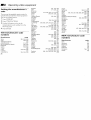
Operating
Setting
code
the
video
manufacturer's
Y'ou can use the supplied
remote
operate
Sony or non-Sony
video
that has an infrared
sensor.
1 Press
CODE
2
VTR
Press
3 Use
Press
VCR
to
(FUNCTION).
the 0-9 buttorts
following
control
equipment
SET.
manufacturer's
4
equipment
code
to key in the
number
from
the
chart.
ENTER.
manufacturer
code
numbers
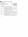
Manufacturer
Sony
Aiwa
Admiral (lVl. Wards)
Audio Dynamic
Bell & Howell (M. Wards)
Broksonic
Canon
Citizen
Craig
Criterion
Curtis Matqis
24
Code
301,302,303
338,344
327
314,337
330,343
319,317
309,308
332
315,302,332
315
304,338,309
Daewoo
341,312,309
DBX
314,336,337
Dimensia
304
Emerson
319,320,316,317,318,341
Fisher
330,334, 335,333
Funai
338
General Electric
329,304,309
Go Video
322
Gotdstar
332
Hitachi
306,304, 305,338
Instant Replay
309,308
JC Penney
309,305,304,330,314,336,337
JVC
314,336,337
Kenwood
314,336,332,337
LXl(Sears)
332,305,333,334,330,335,338
Magnavox
308,309,310
Marantz
314,336,337
Marts
332
Memorex
309,335
Minolta
305,304
Mitsubishi/MGA
323,324,325,326
Multitech
325,338,321
NEC
314,336,337
Olympic
309, 308
Qptimus
327
Panasonic
308,309,306,307
Pentax
305,304
Philco
308,309
Philips
308,309,310
Pioneer
308
Quasar
308,309,306
RCA/PROSCAN
304,305,308,309,311,
312,313,310,329
Realistic
309,330,328,335,324,338
Sansui
314
Singer
315
Samsung
322, 313,321
Sanyo
330,335
Scott
312,313,321,335,
323,324, 325,326
Sharp
327, 328
Shintom
315
Signature 2000 (M. Wards)
338,327
Sylvania
308,309,338,310
Symphonic
338
SV2000
338
Tashiro
332
Tatung
314, 336,337
Teac
314,336, 338,337
Technics
309,308
Toshiba,
312,311
Wards
327,328,335,
331,332
XR-100O
315
Yamaha
330, 314, 336,337
Zenith
331
MDP
manufacturer
code
numbers
Manufacturer
Sony
Kenwood
Magnavox
Marantz
Mitsubishi
Panasonic
Philips
Code
701
707
703
702
702
704, 710
703
oneer
CA
_nyo
aarp
amaha
702
702,709
706
705
703,708
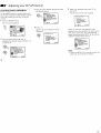
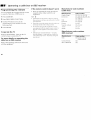
Operating
a VCR
To turn on or off
To select a channel
Buttons on the
remote control
Operating
Press VTR (POWER).
Press the 0 - 9 buttons.
To turn on or off
Press VTR (POWER).
To play
Press the I_-.
To stop
Press U.
Press II.
To resume normal
directly
h_ some rare cases, you may not be able to o])erate
your non-Sony video equipment with the supphed
remote control. In this case, please use the
equipmem's own remote control.
The code _;:umbers for Sony equipment are assig_led at
the facto G, as follows:
VHS
VCR
301 (preset:
the supplied
control)
8 mm VCR
302
Beta, ED Beta VCRs
303
code
for
remote
When you remove the batteries, the code number may
revert to the factory setting.
an MDP
To change
channels
Press CH +/-.
To pause
To record
Press _ while pressing @.
First release I),-, then
release O.
To search the picture
forward o)backward
To play
Press I),--.
To stop
Press B.
To fast forward
Press I_1_.
To rewind the tape
Press 4t41.
To pause
Press II.
To resume normal playback,
press again.
To search the
picture forward or
backward
Press I_ or _
during
playback.
To resume normal playback,
release the button.
To change input
mode
Press TV/VTR.
But:tons on the
remote control
playback, press again.
Keep pressing I_ or "_
during playback.
To resume normal
playback, release the
butlon.
To search the
chapter fcrward or
backward
Press CH +/-.
25
Operating
Programming
the
a cable
box
or DBS receiver
If the
remote
1 Press
CODE
the supplied
rernote
box or DBS receiver.
DBS/CABLE
Use the 0-9 buttons
to key in the
manufacturer's
code number
from
Press
(FUNCTION).
the
•
chart.
•
ENTER.
To operate
the
TV
•
Press TV (FUNCTION).
Then use the TV
,control battons to control the TV.
For more details
on operating
cable box or DBS receiver
Refer to the operating
with the equipment.
instructions
doesn't
work
try repeating
the setup procedures
the other codes listed for your
equipment.
•
3
4
First,
using
Tips
Press
following
control
SET.
2
control
Manufacturer
(cable
•
You can program
re) operate
a cable
remote
the
that come
"_"
If you enter a new code lll?tllber, tlle code Hltlllber you
previo_sly entered at that setting is erased.
numbers
box)
Manufacturer
Code
HamliniRegal
222, 2:!3, 224, 225, 226
JerroldiG.
If more than one code m_mber is listed, try cnterMg
them one by one until you come to tlte correct code for
your equipment.
code
I.
number
201,202, 203, 204, 205, 206,
207, 208, 218
Oak
227, 228, 229
Panasonic
2[9, 220, 221
Pioneer
Scientific
214, 2_ 5
Atlanta
209, 2_ 0, 211
Tocom
216, 2_.7
yo_r equipment with the supplied remote control In
this case, use the equipment's own remote control
unit.
Zenith
212, 2_ 3
Whenever you remove the batteries -- to replace
them, for example -- it: too ,'m_ch time is ta],e_;,the
code m_mbers may revert re,the factory setting and
must be reseL
(DBS receiver)
l_l
SO!lie
rare
cases,
IjOl?
ilia!]
Ilo[
be
able
to
o_2_:rale
Manufacturer
code
numbers
Manufacturer
Code
Son),
801 (preset code for
re mote control)
Genera[
Electric
RCA/PROSCAN
802
802
number
IJ
Troubleshooting
Troubleshooting
Cannot Operate Single-Tuner
Z7V26, 29RS26, 29RS26C, 29V66M,
]4RS26C, 3.=;S26, 37RS26 only)
PIP (KV-27S26,
32S26, 32TW26,
Check that cable is connected to the VCR,
and the VCR is turned
on.
•
Perform AUTO SET UP again using the
SET UP button to return to the factory
preset condition. (page 13)
•
Remove objects from the front of TV.
Check the LIGHTSENSOR setting in the
VIDEO menu. (page 19)
Check that the VCR is connected to the TV.
_o picture (screen not lit), no sound
Make sure the power cord is plugged in.
Operate with the buttons on the TV and the
remote control.
Insert the batteries in the remote control
with the correct polarity.
•
Replace the batteries with new ones if they
are weak.
Good picture, no sound
• Press MUTING so that "MUTING"
disappears from the screen. (page 14)
• Check the MTS setting in the AUDIO
menu. (page 20)
• Make sure SPEAKER is set to ON in the
AUDIO menu. (page 20)
• Perform AUTO SET UP again using the
SET UP button to return to the factory
preset condition. (page 13)
Check 1:osee if the TV/VIDEO setting is
correct: when watching TV, set to TV, and
when watching video tapes, set to VIDEO1,
2, or 3.
Try ancther channel. It could be station
trouble.
Perform AUTO SET LIP again using the
SET UP button to return to the factory
preset condition. (page 13)
Black and white programs cannot be seen
in color.
Poor or no picture (screen lit), good sound
• Adjust PICTURE in the VIDEO menu. (page 19)
• Adjust BRIGHTNESS in the VIDEO menu.
(page 19)
• Check antenna!cable connections.
When one of the video inputs is labeled as
WEB, the screen will darken significantly,
creating an ideal picture for WebTV
viewing. (page 23)
No color
•
Adjust the COLOR in the VIDEO menu.
(page 19)
Perform AUTO SET UP again using the
SET UP button to return to the factory
preset condition. (page 131)
Only snow and noise appear on the screen
Check EheCABLE setting n the SET UP
menu. ,'page 22)
• Check Ihe antenna/cable connections.
•
Make sure the channel is broadcasting
prog'arns.
•
Press AN-i" to change the input mode.
(page 15)
Dotted lines or stripes
•
Adjust :he antenna.
•
Mow) the TV away from noise sources
such as cars, neon signs, or hair-dryers.
Double images or ghosts
•
Use a highly directional outdoor antenna or
a cable (wqen the problem is caused by
reflections from nearby mountains or tall
buildings).
Cannol operate menu
•
If the, item you want to choose appears in
gray you cannot select it. Press TV/
VIDEO correctly.
27
Troubleshooting
(continued)
"annot receive upper channels (UHF)
vhen using an antenna
Make sure CABLE is OFF in the SET UP
menu. (page 22)
Use AUTO PROGRAM to add receivable
channels that are not presently in TV
memory. (page 22)
_,annot receive
-able TV
any channels
Cannot gain enough
cable box
•
:{emote control does not operate
Batteries could be weak. Replace the
batteries.
Increase the volume at the cable box.
Then press TV (FUNCTION) and adjust
the TV's volume.
TV malfunctions
when using the S-Link
function (KV-27V26, 27V36, 29V36C, 29V66M,
Make sure the TV's power cord is
connec, ted securely to the wall outlet.
29V76M,
Locate the TV at least 3-4 feet away from
fluorescent lights.
•
Check the S-Link connection.
•
(page 4,5)
when using a
Try turning CHANNEL FIX off. (see page
22)
Use AUTO PROGRAM to add receivable
channels that are not presently in the TV
memory. (page 22)
To reset the TV: First, turn the TV on.
Then, while pressing the RESET key on
the remote control, press the POWER Key
on the TV. The TV will turn itself off. then
back on. When the TV turns on again, all
settings will be reset, and the EASY
SETUP GUIDE will appear.
when using
when operating
volume
TV is fixed to one channel
Make sJre CABLE is ON in the SET UP
menu. (page 22)
Use ALITO PROGRAM to add receivable
channels that are not presently in TV
memory. (page 22)
Press TV (FUNCTION)
your TV.
Specifications
37V36M
32V26,
32V36,
34V36C,
35V36,
35V76,
only)
Make sure the TV's power cord is
connected securely to the wall outlet.
Check the S-Link connection. (page 4,5)
Supplied
accessories
Remote control RM-Y136A (1 I
(KV-27S26, 27S36, 29RS26, 29RS26C,
32S26, 32S36, 32TW26, 34RS26C,
35S26, 35S36, 37RS26 only)
Remote control RM-Y137A (1)
(KV-27V26, 27V36, 29V36C, 29V66M,
29V76M, 32V26, 32V36, 3,4V36C, 35V36,
35V76, 37V36M only)
Batteries (2) size AA (R6)
OptionLal
accessories
Connecting cables
VMC-810S/820S, VMC-720M, YC-15V/
30V, RK-74A
TV Stand SU-27A
(KV-27S26, 27S36, 27V26, 27V36,
29RS26, 29RS26C, 29V36C, 29V66M,
29V/6M (except Canadian models))
TV Stand SU-32A
(KV-32S26, 32S36, 32V26, 32V36,
34RS23C, 34V36C (except Canadian
models))
TV Stand SU-35A
(KV-35V36, 35S26, 35S36, 37RS26,
37V361vl (except Canadian models))
U/V mixer EAC-66
Specifications
(continued)
KV-
27S26
27S36
27V26
27V36
29RS26
29RS26C
29V36C
223V,50;60Hz
20V,50,60Hz
120 V. 60 Hz
120 V, 60 Hz
120 V, 60 Hz
120 V, 60 Hz
120 V, 60 Hz
2
2
3
3
2
2
1
1
1
1
1
1
Aud io !:)
2
2
3
3
2
Audio
1
1
1
1
1
1
_ower
requirements
Number
29V66M
29V76M
120 V, 60 qz
120 V, 60 Hz
3
3
3
1
1
1
2
3
3
3
1
1
1
1
1
1
1
1
1
1
ot inputs/outputs
Video
_)
S Video
2)
out 4)
Monitor
out 7)
TV out _)
1
S-Link
Speaker
output
Dimensions
(mm)
(in.)
5Wx2
(W)
Power consumption
In use ,[Max.)
In standby
5Wx2
5Wx2
lOWx2
5Wx2
5Wx2
lOWx2
5Wx2
lOWx2
(W)
(W/H/D)
Mass (kg)
(Ibs)
elevision
system
American TV standard
hannel coverage
VHF: 2-13!UHF:
14 %9/CATV: 1 -125
icture tub{:
Hi Black Trinitron ®tube
isible screen size
2F-inch picture measured
diagonally
ctual screen size
29-inch picture measured
d!.agonally
ntenna
75 ohm ex:ernal tern'dnal for VHFiUHF
165W
180W
180W
195W
165W
165W
195W
180W
9W
9W
9W
13W
9W
9W
13W
9W
13W
690 x 575.4
690 x 575.4
660.4 x 602.5 x
66C.4 x 602.5 x
390 x 575.4
690 x 575.4
690 x 575.4
660,4 x 602.5 x
660.4
x 602.5 x
'
195W
521.2 mm
521.2 mm
x 503.4 mm
521.2 mm
621.2 mm
( 503.4 mm
26 x 23 3/4
26 x 23 3/4
27 74 x 22 3/4
27 V_ x 22 3/4
26 x 23 %
26 x 23 3/,
!7 % x 22 3/4
27 _4 x 22! 3/4
x 20 ;/8 in.
x 20 % in.
x 19 71_in.
x 19 % in.
x 20 % in.
>:20 '.,'6 in.
x 19 % in.
x 19 % in.
41 kg
42 kg
43 kg
43kg
4! kg
43kg
43 kg
43 kg
90 Ibs 7 oz
92 qbs 10 oz
94 Ibs 13 oz
94 Ibs 13 oz
90 Ibs 7 oz
)4 Ibs 13 oz
94 Ibs 13 oz
94 Ibs 13 oz
x 5034 mm
'_
1 Vp-p,
:'
Y: 1 Vp-p, 715ohms unbalanced,
syr, c r,egative
C: 0.286 Vp-p (Burst signal), 75 ohms
75 ohms unbalanced,
_
500 mVrms
kilohms
41kg
90 Ibs 7 oz
x 503.4 mm
27 V4 x 22 :V4
x 19%in.
sync r_egative
(O)
(100% modulation),
x 503.4 rr m
Impedance:
More than 408 mVrms at the maximum
setting (variable)
More than 408 mVrms (fix)
Impedance:
50 kilohms
47
volume
_ SRS
(SOUND
RETRIEVAL
SYSTEM)
The (0) SRS (SOUND RETRIEVAL SYSTEM) is
manufactured by Sony Corporation under license
from SRS Labs, inc. It is covered IzyU.S. Patent No.
4,748,669. O:her U.S. and foreign
patents
pending.
Theregistered
word 'SRS'
and the SRS
symbol
trademarks
of SR_
Labs, (O)
Inc.are
29
Specifica
tions
KV-
Power requirements
(continued)
32S26
32S36
32TW26
32V26
32V36
34RS26C
34V36C
35S26
120V, EOHz
120V,60Hz
120V, 60Hz
12OV. 60Hz
120V,60Hz
_3V,50_60Hz
220V, 50/60Hz
120V. 6CHz
35S36
120V,6C
35V36
35V76
37RS26
12CV, 6OHz
120 V, 60Hz
7V36M
120 V,60 Hz 120V,60 Hz
Number of inputs/outputs
"
Video 1)
2
2
2
3
3
2
3
2
2
3
3
2
3
S Video 2)
1
I
1
1
2
1
2
1
1
2
2
1
2
2
2
3
3
2
3
1
1
1
1
1
1
1
1
1
1
5Wx2
10Wx2
215W, 2.80A
225W
13W
13W
13W
13W
920 x 730 8
920 x 1207
870 x761
920 x 730.6
2
Audio 3)
Audio out 4)
Monitor
I
2
1
2
1
out _)
3
3
2
3
I
1
1
1
1,
t
1
1
1
TV out 1}
1 11
t
S-Link
Speaker output
(W)
Power consumption (W)
When in use (Max.)
In standby
Dimensions
(mm)
(in.)
Mass (kg)
(Ibs)
(W/H/D)
5Wx2
5Wx2
10Wx2
5Wx2
5W:,:2
5W x 2
185W
190W
185W
190W
210W, 275A
185W
21cW
9W
9W
9W
9W
13W
9W
137,/
781 x712.1
781 x 712.1
942 x 1133.1
821 x 675.3
821 x 675.3
781 x 7121
821 × 6753
x 582.8mm
x582.5 mm
x661 5 mm
x 587 mm
x 587 mm
,_582.5 mm
x 587 mm
303hx28%
x 2qln.
642 kg
141bs12ez
Television
system
American
TV standard
Channel
coverage
VHF: 2-13/UHF:
14 -69/CATV:
1 - 125
Picture tube
Hi Black Trinitron ®tube
Antenna
75 ohm external terminal
for Vt-[F/UHF
303/4 x28%
x23i&
I 37%x44%
x26 %in.
33'h_27%
x24in,
66 kg
!089 kg
70 kg
1451bsgoz
2401bs
1541bs6oz
33V2x27%
x24in,
70 kg
154!bs6oz
_0_4 x28%
x 23in.
5W×2
13W x 2
33:,2x27%
x24]n
215W, 230 A 215W, 2.
13_h
132_
870x_61
870xJ
x 653 r',m
x653 r
x ,_41.8mm
34 '/4 x 30
34V._x
i 37 % x 29%
x 25s/_in.
x 25sL
64.3kg
70 kg
83 kg
1411bs12oz
1541bs6oz
182[bsi.6oz
Visible screen size
32-inch picture measured
diagonally
32TW26, 32V26, 32V36, 34V36C)
35-inch picture measured
diagonally
35V36, 35V76, 37RS26, 37V36M )
Actual screen size
34-inch picture measured
diagor, ally
32TW26, 32V26, 32V36, 34V36C)
37-inch picture measured
diagonally
35V36, 35V76, 37RS26, 37V36M )
5Wx
83 kc
82bsi
5Wx2
215W, 2.80A 215W, 2 80 ,_
x713 mm
x653 mm
x 641.8mm
37 % x 49%
34 _k x 30
37%x29%
x 26 74in.
x 28 :,'ein.
x 25 % in
x 26 V._
in.
90kg
130 kg
63 kg
90 kg
1£6 Ibs7 oz
279 Ibs6 oz
182 Ibs9.6 oz 198 Ibs7 oz
_'
1 Vp. p, 75 oh'ns
(KV-32S26, 32S36,
-"
3r: 1 Vp-p. 75 oh.ms unbalanced,
syn,: negative
C: 0.286 Vpqo (Burst signal), 75 ob, n;s
(KV-35S2fi, 35S36,
3,
500 nlVr[l_.s (]00c)_ modulation),
_
Mot,: than 40:} mVrms
(variabl,)
More thai', 40"; mVrms
(KV-32S26,
32S36,
(KV-35S26,
35S36,
Imp{dal
Design
change
5Wx2
unbalanced,
sync r, egative
Impedance:
at the maximum
47 kilohms
volume
selting
(Bx)
ce: 53 kilohms
and specifications
without
notice.
are subject
to
Index
djusting your SET UP ............................................
NT .............................................................................
ntcnna cable ...............................................................
ntenna connector ......................................................
UDIO button ...........................................................
UDIO menu operations
2
AUDIO OUT ..........................................................
BALANCE .............................................................
BASS .......................................................................
EFFECT ..................................................................
MTS .........................................................................
SPEAKER ...............................................................
TREBLE ..................................................................
UDIO OUT
FIXED ......................................................................
VARIABLE .............................................................
udio Video Cable ......................................................
[.;TO PROGRAM ....................................................
UTO SET UP ............................................................
UX Hookup
.........................................................
18
15
3
2
16
20
20
20
20
20
20
20
20
20
2
22
22
3, 15
Caption Vision ...........................................................
CATV cable ...................................................................
Coaxial cable .........................................................
2,
CH +/-. .......................................................................
CHANNEL
ERASE!ADD ........................................
CHANNEL
BLOCK ..................................................
CHANNEL
CAPTION ..............................................
CHANNEL
FIX .........................................................
COLOR ........................................................................
Connecting
antenna
TV to
.....................................................................
audio system ...........................................................
AV receiver ..............................................................
cable ..........................................................................
cable box and cable .................................................
camcorder ................................................................
DBS receiver ............................................................
DBS receiver and VCR ...........................................
two VCRs .................................................................
VCR ...........................................................................
CURRENT TIIvIE SET ...............................................
15
3
4, 5
14
22
23
22
22
19
3
7
7
3
3
9
6
6
8
4
21
D
DAYLIGHT SAVING ................................................
\LANCE .................................................................. 20
\SS ............................................................................
20
DBS receiver operation
.............................................
DISPLAY
utery installation .................................................... 12
_IGHTNESS ............................................................. 19
Caption vision .......................................................
\BLE ......................................................................... 22
_blebox .................................................................. 3, 5
operation ................................................................ 26
21
26
15
Status ......................................................................
15
XDS ......................................................................... 15
E
Easy Setup Guide .......................................................
13
Editing using monitor out .......................................... 8
EFFECT
S1MULA_fED......................................................... 20
SRS .......................................................................... 20
Surround ................................................................ 20
F
Factory settings .................................................... 19, 20
FAVORITE CHANNEL ............................................ 23
FAVORITE CHANNEL W / PREVI EW .................. 23
Features table ............................................................... 1
FREEZE butlon ................................................... 14, 17
G
Glass door installation .............................................. 10
Adjusting shelf .......................................................11
Parts li.st.................................................................. 10
tt
Hook Ups ...................................................................... 2
HUE ............................................................................. 19
I, d, K
[nput-source mode .................................................... 16
lUMP button ............................................................... 14
t.
Language selection .............................................. 13, 23
Learning menus
AUDIO .................................................................. 20
SET UP. .................................................................. 22
TIMER ................................................................... 21
VIDEC ................................................................... 19
L1GHTSENSORTM ...................................................... 13
31
SWAP .....................................................................
TV/VIDEO
............................................................
TViVTR CH + .......................................................
M,N
MDP operation
Menu selection
...........................................................
...........................................................
Mode
MOVIE ...................................................................
SPORTS ..................................................................
STANDARD ..........................................................
Monitor out ..................................................................
Mono ............................................................................
MTS
MAIN .....................................................................
SAP .........................................................................
MONO ....................................................................
MUTING button ........................................................
24
18
Programming
19
19
19
8
20
20
20
20
14
O
On Line Help ..............................................................
ON/OFF TIMER ........................................................
12
21
Other video equipment .............................................
Operating video equipment .....................................
24
24
P, Q
Picture-in-.Picture
(PIP)
Main picture ..........................................................
Window picture ....................................................
PIP conne:tions
(single tuner) .................................
PIP operations
AUDIO ...................................................................
CH+i-. ...................................................................
FREEZE ..................................................................
PIP ...........................................................................
POSITION ..............................................................
16
16
16
16
17
16
]6
17
the remote
.........................................
17
16
16
Specifications
Splitter ...........................................................................
SWAP button ..............................................................
5
17
26
T,U
TILT CORRECTION
FI
Remote control ...........................................................
14
Function buttons .............................................
14, 15
Graphic
Illustration
..........................
(inside cover)
S
SAP ..............................................................................
S-Link cable ..................................................................
S-Link connector ..........................................................
S-Link function .............................................................
S Video cable ................................................................
20
2
9
9
2
Safety ............................................................................
Select buttons .............................................................
1
12
Adjusting sliders ...................................................
SET UP menu _
...................................................
AUTO PROGRAM ....................................................
CABLE ...................................................................
CHANNEL
ERASE/ADD
...................................
CHANNEL CAPTION .........................................
12
22
22
22
22
22
CHANNEL
FAVORITE
BLOCK .............................................
CHANNEL
......................................
Setting up TV ..............................................................
SHARPNESS
..............................................................
SLEEP button .............................................................
SPEAKER
ON ..........................................................................
OFF ........................................................................
23
23
13
19
15
20
20
..................................................
28, 29, 30
.................................................
23
TIMER menu operations
if)
CURRENT TIME SET ...........................................
DAYLI _,HT SAVING ...........................................
21
21
ON/OFF TIMER ...................................................
TREBLE .......................................................................
21
20
Troubleshooting
...................................................
27,
TV (FUNCTION) button ...........................................
TV POWER button ....................................................
TV/VII)ED button .....................................................
28
14
14
15
V, W, X, _, Z
VCR ........................................................................
4, 5, 8
VCR manufacturer
code numbers .......................... 24
VCR oper _tion ............................................................
VIDEO LABEL ...........................................................
25
23
VIDEO menu operations
{._
BRIGHTNESS ........................................................
COLOR ...................................................................
HUE ........................................................................
LIGHT3ENSOR
.....................................................
MODE .....................................................................
19
19
19
19
19
PICTURE ................................................................
S[-IA R] 'NESS .........................................................
VOL +/-. .....................................................................
VTR ..............................................................................
XDS ..............................................................................
19
19
14
24
15