1
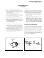
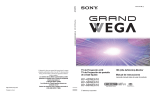
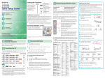
Thanks for your interest in
servicemanuals.net
Attached are a couple pages from the
manual so you can make sure if it what
you are looking for and so you can see the
quality of the manuals we provide.
We look forward to receiving your order.
To order, please go to
click here
SERVICE MANUAL
MODEL
––––––
KF-42WE610
KF-42WE610
KF-50WE610
KF-50WE610
KF-60WE610
KF-60WE610
COMMANDER
NO.
–––––––––––– DEST.
––––– CHASSIS
–––––––––––
RM-Y913
US
RM-Y913
Canadian
RM-Y913
US
RM-Y913
Canadian
RM-Y913
US
RM-Y913
Canadian
MODEL
––––––
LA-2 CHASSIS
COMMANDER
NO.
–––––––––––– DEST.
––––– CHASSIS
–––––––––––
VCR/
DVD
MUTING
SAT/ POWER
CABLE
MODE
DISPLAY
PICTURE WIDE
JUMP
ENT
FAVORITES
MENU
VCR/DVD
SAT/
CABLE
TV
FUNCTION
TV/VIDEO
FREEZE
/TV/SAT
ANT
GUIDE
VOL
CH
CODE SET RESET
SLEEP MTS/SAP
TV
RM-Y913
KF-42WE610/50WE610/60WE610
RM-Y913
LCD PROJECTION TV
KF-42WE610/50WE610/60WE610
K
RM-Y913
RM-Y913
Specifications
Projection System
LCD Panel
Projection Lens
Antenna
Lamp
Television System
Screen Size (measured diagonally)
Channel Coverage
VHF
UHF
CATV
Power Requirements
Number of Inputs/Outputs
DVI-HDTV
Video (IN)
S Video (IN)
Audio (IN)
AUDIO (VAR/FIX)
CONTROL S (IN/OUT)
Component Video Input
RF Inputs
Converter
Speaker Output
Dimensions (W ◊ H ◊ D)
Mass
Power Consumption
In Use
In Standby
3 LCD Panels, 1 lens projection system
0.87 inch TFT LCD panel Approx. 3.28 million dots (1,092,168 pixels)
High Performance, large diameter hybrid lens F2.4
75 ohm external terminal for VHF/UHF
UHP lamp, 100W
XL-2100U
NTSC, American TV Standard
KF-42WE610: 42 inches, KF-50WE610: 50 inches, KF-60WE610: 60 inches
2-13
14-69
1-125
120V, 60 Hz
1 terminal, 3.3 V T.M.D.S., 50 ohms
The DVI-HDTV input terminal is compliant with the EIA-861 standard and is
not intended for use with personal computers.
4
1 Vp-p, 75 ohms unbalanced, sync negative
4
Y: 1 Vp-p, 75 ohms unbalanced, sync
negative
C: 0.286 Vp-p (Burst signal), 75 ohms
6
500 mVrms (100% modulation)
Impedance: 47 kiloohms
1
500 mVrms at the maximum volume setting
(Variable)
500 mVrms (Fixed)
Impedance (output): 2 kiloohms
1
minijacks
2 (Y, PB, PR)
Y: 1.0 Vp-p, 75 ohms unbalanced, sync
negative
PB: 0.7 Vp-p, 75 ohms
PR: 0.7 Vp-p, 75 ohms
2
1
5W (L), 5W (R), 20W (Woofer)
KF-42WE610: 1,201 x 819 x 371 mm (47 1/4 x 32 1/4 x 14 1/2 inches)
KF-50WE610: 1,377 x 928 x 452 mm (54 1/4 x 36 1/2 x 17 3/4 inches)
KF-60WE610: 1,619 x 1,067 x 541 mm (63 3/4 x 42 x 2 1 1/4 inches)
KF-42WE610: 32 Kg (70 lb 12 oz) KF-50WE610: 39.5 kg (87 lb 1 oz),
KF-60WE610: 49.5 kg (109 lb 2 oz)
210 W
Under 1 W
–2–
RM-Y913
KF-42WE610/50WE610/60WE610
K
Supplied Accessories
Remote Control
AA Batteries
Cleaning Cloth
Optional Accessories
TV Stand
Lamp
AV Cable
Control S Cable
Component Video Cable
AV Receiver
Memory Stick media
RM-Y913
RM-Y913
RM-Y913
2 supplied for remote control
1
SU-GW1 (for KF-50/60WE610), SU-GW2 (for KF-42WE610)
XL-2100U
VC-810S/820S/830S
RK-G69
VMC-10/30
STR series or equivalent
8MB (MSA-8A), 16MB (MSA-16A), 32MB (MSA-32A), 64MB (MSA-64A),
128MB (MSA-128A)
Design and specifications are subject to change without notice.
–3–
RM-Y913
KF-42WE610/50WE610/60WE610
K
RM-Y913
RM-Y913
RM-Y913
SAFETY CHECK-OUT
( US model only )
After correcting the original service problem, perfom the following safety checks before releasing the set to the customer:
l. Check the area of your repair for unsoldered or poorly-soldered connections. Check the entire board surface for solder
splashes and bridges.
2. Check the interboard wiring to ensure that no wires are
“pinched” or contact high-wattage resistors.
3. Check that all control knobs, shields, covers, ground straps,
and mounting hardware have been replaced. Be absolutely
certain that you have replaced all the insulators.
4. Look for unauthorized replacement parts, particularly transistors, that were installed during a previous repair. Point them
out to the customer and recommend their replacement.
5. Look for parts which, through functioning, show obvious
signs of deterioration. Point them out to the customer and
recom mend their replacement.
6. Check the line cords for cracks and abrasion. Recommend
the replacement of any such line cord to the customer.
7. Check the condition of the monopole antenna (if any). Make
sure the end is not broken off, and has the plastic cap on it.
Point out the danger of impalement on a broken antenna to
the customer, and recommend the antenna’s replacement.
8. Check the B+ and HV to see they are at the values specified.
Make sure your instruments are accurate;be suspicious of
your HV meter if sets always have low HV.
9. Check the antenna temminals, metal trim, “metallized” knobs,
screws, and all other exposed metal parts for AC leakage.
Check leakage as described below.
To Exposed Metal
Parts on Set
LEAKAGE TEST
The AC leakage from any exposed metal part to earth ground and
from all exposed metal parts to any exposed metal part having a
return to chassis, must not exceed 0.5mA (500 microampers) . Leakage current can be measured by any one of three methods.
1. A commercial leakage tester, such as the Simpson 229 or
RCA WT-540A. Follow the manufacturers’ instructions to
usc these instruments.
2. A battery-operated AC milliammeter. The Data Precision 245
digital multimeter is suitable for this job.
3. Measuring the voltage drop across a resistor by means of a
VOM or battery-operated AC voltmeter. The “limit” indication is 0.75V, so analog meters must have an accurate lowvoltage scale. The Simpson 250 and Sanwa SH-63Trd are
examples of a passive VOM that is suitable. NearIy all battery operated digital multimeters that have a 2V AC range
are suitable. (See Fig. A)
HOW TO FIND A GOOD EARTH GROUND
A cold-water pipe is guaranteed earth ground;the cover-plate retaining screw on most AC outlet boxes is also at earth ground. If
the retaining screw is to be used as your earth-ground, verify that it
is at ground by measuring the resistance between it and a coldwater pipe with an ohmmeter. The reading should be zero ohms. If
a cold-water pipe is not accessible, connect a 60-l00 watts trouble
light (not a neon lamp) between the hot side of the receptacle and
the retaining screw. Try both slots, if necessary, to locate the hot
side of the line, the lamp should light at normal brilliance if the
screw is at ground potential. (See Fig. B)
Trouble Light
Ohmmeter
AC Outlet Box
1.5 µ F
1.5k Ω
AC
voltmeter
(0.75V)
Cold-water Pipe
Earth Ground
Fig. B. Checking for earth ground.
Fig. A. Using an AC voltmeter to check AC leakage.
–4–
KF-42WE610/50WE610/60WE610
K
CAUTION
These servicing instructions are for use by qualified service personnel only.
To reduce the risk of electric shock, do not perform any servicing
other than that contained in the operating instructions unless you
are qualified to do so.
WARNING!!
AN ISOLATION TRANSFORMER SHOULD BE USED DURING
ANY SERVICE TO AVOID POSSIBLE SHOCK HAZARD, BECAUSE OF LIVE CHASSIS.
THE CHASSIS OF THIS RECElVER IS DIRECTLY CONNECTED
TO THE AC POWER LINE.
SAFETY-RELATED COMPONENT WARNING!!
COMPONENTS IDENTIFIED BY SHADING AND MARK ! ON THE
SCHEMATIC DIAGRAMS, EXPLODED VIEWS AND IN THE
PARTS LIST ARE CRITICAL TO SAFE OPERATION. REPLACE
THESE COMPONENTS WITH SONY PARTS WHOSE PART NUMBERS APPEAR AS SHOWN IN THIS MANUAL OR IN SUPPLEMENTS PUBLISHED BY SONY. CIRCUIT ADJUSTMENTS THAT
ARE CRITICAL TO SAFE OPERATION ARE IDENTIFIED IN THIS
MANUAL. FOLLOW THESE PROCEDURES WHENEVER CRITICAL COMPONENTS ARE REPLACED OR IMPROPER OPERATION IS SUSPECTED.
–5–
RM-Y913
RM-Y913
RM-Y913
ATTENTION!!
AFIN D’EVITER TOUT RISQUE DELECTROCUTION PROVENANT D’UN CHÁSSIS SOUS TENSION, UN TRANSFORMATEUR
D’ISOLEMENT DOIT ETRE UTILISÉ LORS DE TOUT DEPANNAGE.
LE CHÁSSIS DE CE RECEPTEUR EST DIRECTEMENT RACCORDÉ Á L’ALIMENTATION SECTEUR.
ATTENTION AUX COMPOSANTS RELATIFS ÁLA
SÉCURITÉ!!
LES COMPOSANTS IDENTIFIÉS PAR UNE FRAME ET PAR UNE
MAPQUE ! SUR LES SCHÉMAS DE PRINCIPE, LES VUES EXPLOSÉES ET LES LISTES DE PIECES SONT D’UNE IMPORTANCE
CRITIQUE POUR LA SÉCURITÉ DU FONCTIONNEMENT. NE LES
REMPLACER QUE PAR DES COMPOSANTS SONY DONT LE
NUMÉRO DE PIÉCE EST INDIQUÉ DANS LE PRÉSENT MANUEL OU DANS DES SUPPLÉMENTS PUBLIÉS PAR SONY. LES
RÉGLAGES DE CIRCUIT DONT L’IMPORTANCE EST CRITIQUE
POUR LA SÉCURITÉ DU FONCTIONNEMENT SONT IDENTIFIES
DANS LE PRÉSENT MANUEL. SUIVRE CES PROCÉDURES
LORS DE CHAQUE REMPLACEMENT DE COMPOSANTS CRITIQUES, OU LORSQU’UN MAUVAIS FONCTIONNEMENT SUSPECTÉ.
KF-42WE610/50WE610/60WE610
K
RM-Y913
RM-Y913
RM-Y913
TABLE OF CONTENTS
Section
––––––
Title
––––
1. SELF DIAGNOSIS FUNCTION .....................
Page
––––
8
Section
––––––
4-4.
(1)
(2)
(3)
(4)
(5)
(6)
(7)
(8)
(9)
(10)
(11)
(12)
(13)
(14)
(15)
(16)
(17)
2. DISASSEMBLY
2-1.
Rear Cover .........................................................
12
2-2.
Center Pillar .......................................................
12
2-3.
Service Position .................................................
12
2-4.
Chassis Assembly, Optical Unit Block,
D.C.Fan ...............................................................
13
2-5.
UD Board, RF Antenna Switch .........................
13
2-6.
U Board ...............................................................
13
2-7.
F and G1 Boards .................................................
14
2-8.
DIC Bloack, AU and C2 Boards ........................
14
2-9.
A Board ...............................................................
15
2-10. Power Supply Block ...........................................
15
2-11. T Board ...............................................................
15
2-12. H3 Board (42WE610) ........................................
15
2-13. Front Cover Assembly .......................................
16
2-14. HM and H3 Boards (50WE610/60WE610) .......
16
2-15. H2 Board .............................................................
17
2-16 HM Board (42WE610) ......................................
17
2-17. Screen Mirror Block Assembly .........................
18
2-18. H1 Board .............................................................
18
4-5.
19
3-1-1. Method of Setting the Service Adjustment
Mode ...............................................................
3-1-2. Service Mode Adjustment ............................
3-1-3. Memory Write Confirmation Method ..........
3-1-4. Adjusting Buttons and Indicator ...................
3-1-5. Service Mode List ..........................................
19
19
19
19
21
Sub Color/Sub Hue Adjustment ........................
Printed Wiring Boards ........................................ 117
• A Board (Side B) ............................................. 118
• AU Board ......................................................... 119
• F Board ............................................................. 120
• G1 Board (Side A) ........................................... 121
• G1 Board (Side B) ........................................... 122
• H2 Board .......................................................... 124
• H3 Board .......................................................... 125
• HM Board ........................................................ 126
• T Board ............................................................. 127
• U Board (Side A) ............................................. 128
• U Board (Side B) ............................................. 129
• UD Board ......................................................... 130
90
4. DIAGRAMS
4-1.
100
101
102
103
104
105
106
107
108
109
110
111
112
113
114
115
116
• H1 Board .......................................................... 123
Electrical Adjustment by Remote Commander ....
3-2.
Schematic Diagram of A (1/4) Board ................
Schematic Diagram of A (2/4) Board ...............
Schematic Diagram of A (3/4) Board ...............
Schematic Diagram of A (4/4) Board ...............
Schematic Diagram of AU (1/2) Board .............
Schematic Diagram of AU (2/2) Board .............
Schematic Diagram of F Board ..........................
Schematic Diagram of G1 Board .......................
Schematic Diagram of H1, H2 Board ................
Schematic Diagram of H3 Board .......................
Schematic Diagram of HM Board .....................
Schematic Diagram of T Board .........................
Schematic Diagram of U (1/3) Board ................
Schematic Diagram of U (2/3) Board ................
Schematic Diagram of U (3/3) Board ................
Schematic Diagram of UD (1/2) Board .............
Schematic Diagram of UD (2/2) Board .............
• A Board (Side A) ............................................. 117
3. ELECTRICAL ADJUSTMENTS
3-1.
Title
Page
––––
––––
Schematic Diagrams ........................................... 99
Block Diagram (1) ..............................................
91
Block Diagram (2) ..............................................
92
Block Diagram (3) ..............................................
93
Block Diagram (4) ..............................................
94
Block Diagram (5) ..............................................
95
Block Diagram (6) ..............................................
96
Block Diagram (7) ..............................................
97
4-2.
Frame Schematic Diagram .................................
98
4-3.
Circuit Boards Location .....................................
99
4-6
IC Block Diagrams ............................................. 131
4-7
Semiconductors .................................................. 132
5. EXPLODED VIEWS
5-1.
KF-42WE610/50WE610
Screen Mirror Block Section ............................ 134
–6–
5-2.
KF-60WE610 Screen Mirror Block Section .... 135
5-3.
Bottom Block ..................................................... 136
5-4.
Chassis-1 ............................................................. 137
5-5.
Chassis-2 ............................................................. 138
5-4.
Optical Unit Block ............................................. 139
KF-42WE610/50WE610/60WE610
K
Section
––––––
Title
––––
Page
––––
6. ELECTRICAL PARTS LIST ............................ 140
• A Board ............................................................ 140
• AU Board ......................................................... 144
• F Board ............................................................. 145
• G1 Board .......................................................... 146
• H1 Board .......................................................... 148
• H2 Board .......................................................... 148
• H3 Board .......................................................... 149
• HM Board ........................................................ 149
• T Board ............................................................. 150
• U Board ............................................................ 150
• UD Board ......................................................... 154
–7–
RM-Y913
RM-Y913
RM-Y913