1
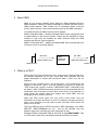
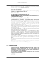
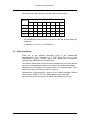
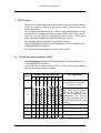
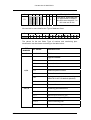
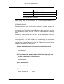
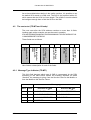
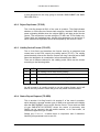
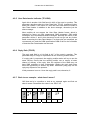
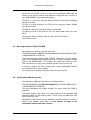
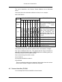
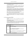
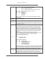
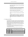
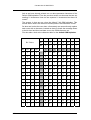
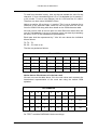
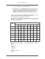
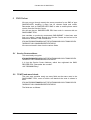
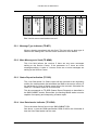
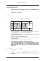
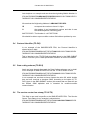
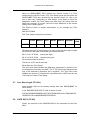
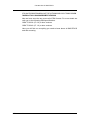
Application Note
Construction of SMS PDU’s
First edition (June 2003)
Sony Ericsson Mobile Communications. publishes this manual without making any warranty as to the
content contained herein. Further Sony Ericsson Mobile Communications. reserves the right to make
modifications, additions and deletions to this manual due to typographical errors, inaccurate information,
or improvements to programs and/or equipment at any time and without notice. Such changes will,
nevertheless be incorporated into new editions of this manual.
All rights reserved.
©
Sony Ericsson Mobile Communications., 2003
Construction of SMS PDU’s
Contents
1
INTRODUCTION.................................................................................................................... 4
2
ABOUT SMS.......................................................................................................................... 5
3
WHAT IS A PDU?.................................................................................................................. 5
3.1
3.2
4
TRANSMISSION ORDER ...................................................................................................... 6
REPRESENTATIONS ........................................................................................................... 7
SMS-SUBMIT ........................................................................................................................ 8
4.1
THE SERVICE CENTER ADDRESS (SCA)............................................................................. 8
4.2
THE NEXT OCTET (TP-MTI AND FRIENDS) ......................................................................... 11
4.2.1
Message Type indicator (TP-MTI) ......................................................................... 11
4.2.2
Reject Duplicates (TP-RD) .................................................................................... 12
4.2.3
Validity Period Format (TP-VPF) ........................................................................... 12
4.2.4
Status Report Request (TP-SRR) ......................................................................... 12
4.2.5
User Data header Indicator (TP-UDHI) ................................................................. 13
4.2.6
Reply Path (TP-RP) ............................................................................................... 13
4.2.7
Back to our example – what does it mean? .......................................................... 13
4.3
MESSAGE REFERENCE FIELD (TP-MR)............................................................................. 14
4.4
DESTINATION ADDRESS (TP-DA)....................................................................................... 14
4.5
PROTOCOL IDENTIFIER (TP-PID) ..................................................................................... 15
4.6
DATA CODING SCHEME (TP-DCS).................................................................................... 16
4.7
VALIDITY PERIOD (TP-VP) ............................................................................................... 19
4.8
USER DATA LENGTH (TP-UDL) ........................................................................................ 20
4.9
USER DATA (TP-UD) ...................................................................................................... 20
5
SMS-DELIVER..................................................................................................................... 25
5.1
SERVICE CENTRE ADDRESS ............................................................................................. 25
5.2
TP-MTI AND MORE FRIENDS ............................................................................................ 25
5.2.1
Message Type indicator (TP-MTI) ......................................................................... 26
5.2.2
More Messages to Send (TP-MMS) ...................................................................... 26
5.2.3
Status Report Indication (TP-SRI) ......................................................................... 26
5.2.4
User Data header Indicator (TP-UDHI) ................................................................. 26
5.2.5
Reply Path (TP-RP) ............................................................................................... 27
5.2.6
Back to our example .............................................................................................. 27
5.3
THE ORIGINATING ADDRESS (TP-OA)............................................................................. 27
5.4
PROTOCOL IDENTIFIER (TP-PID) ..................................................................................... 28
5.5
DATA CODING SCHEME (TP-DCS).................................................................................... 28
5.6
THE SERVICE CENTRE TIME STAMP (TP-SCTS) ................................................................ 28
5.7
USER DATA LENGTH (TP-UDL) ....................................................................................... 29
5.8
USER DATA (TP-UD) ................................................................................................... 29
LZT 123 7632 R1A
3
Construction of SMS PDU’s
1
Introduction
This document is to help an integrator in getting started with sending SMS
messages in the PDU format. Enough information is given here for anyone
to begin constructing the most basic PDU’s and send them, using AT
commands, from one GSM module/mobile to another.
LZT 123 7632 R1A
4
Construction of SMS PDU’s
2 About SMS
SMS, as you already probably know stands for Short Message Service.
SMS provides a means of sending messages of limited size from and to
GSM mobile stations. SMS makes use of something called a Service
Centre, which acts as a store and forward centre for the SMS messages.
Two different types of SMS services can be defined:
Mobile Originated (MO) – Mobile originated SMS will be transported from
a mobile station to the Service Centre. These may be destined for other
mobiles or may even be destined for other services which the GSM
network and Service Centre supports.
Mobile Terminated (MT) – Mobile terminated SMS will be transported from
a Service Centre to a mobile Station.
MO SMS
(SMS-SUBMIT PDU)
SMSSERVICE
CENTER
MT SMS
(SMS-DELIVER PDU)
Mobile Station
Mobile Station
3 What is a PDU?
PDU is short for Protocol Data Unit (or it could even be Packet Data Unit,
the different meanings are in use). These data units represent how the
digital information is coded and structured when it sent over the air
interface.
When we use a mobile phone, we usually enter a text message by the
keypad of the phone, give it a phone number to be sent to, press the
“YES” button and, usually, receive a “MESSAGE SENT” notification from
the phone. With a GSM module this process has to be performed with AT
commands from a terminal of some kind, since there is no keyboard. In
some cases the module does not support text mode SMS, and the
message must be coded as a PDU.
Using the PDU mode gives the user much more power over the
information to be sent and how it is sent. For instance one may not wish to
send a text message, but may wish to send raw Data. PDU format will
allow you to do this.
There are different kinds of PDU involved in SMS messaging, from SMSREPORT, SMS-COMMAND etc. etc. but we will consider only two
different types here, probably the most important as well.
Related to Mobile originated SMS is the PDU of type SMS-SUBMIT. This
is a PDU that is sent from one Mobile terminal to the Service centre.
LZT 123 7632 R1A
5
Construction of SMS PDU’s
Related to Mobile terminated SMS, an SMS that is received by a Mobile
from the Service centre is SMS-DELIVER PDU.
What does a PDU look like?
Well, just to complicate things a PDU is a Service Centre Address (SCA),
followed by a Transport Protocol Data Unit.
PDU = SCA + TPDU
An SMS-SUBMIT PDU looks something like this:
07916407058099F911000A8170607896200000A71554747A0E4ACF416
110945805B5CBF379F85C06
The SCA is shown in bold. The rest is the TPDU.
The PDU format is a hexadecimal encoded binary format, which means
that 2 hexadecimal digits represent a byte of data. When one refers to
Data being transmitted, a byte is usually called an octet (bytes are stored,
and octets are transmitted). The TPDU consists of a header containing
control information, and a “payload” containing the User Data. We will
examine the different parts in detail later.
Some Modules and mobiles do not support the PDU format but only the
TPDU format. In that case it’s just a simple matter to remove the SCA and
work with TPDU only.
You may ask the question: If a SMS must be sent via a Service Centre
doesn’t the SMS have to include the SCA?
The answer here is that the SCA is stored on the SIM card and is taken
from there. It can be changed via the use of AT commands. The good
thing about the PDU format is that by changing the SCA in the PDU the
SMS can be sent via any Service centre of your choice (as long as your
network operator allows it).
If one wishes to use the default SCA (from the SIM card) in the PDU, the
SCA part of the PDU can be replaced with 00. The PDU would look like
this:
0011000A8170607896200000A71554747A0E4ACF416110945805B5CBF
379F85C06
Before we take a look at the meaning of all this hexadecimal and what it
means, we need to consider a few other things first.
3.1
Transmission order
Octets in a PDU are transmitted according to their order. Octets at the
beginning of the PDU are transmitted first. This is the same for the
individual bits of the octets. Thus the low order bits are transmitted first.
Here is an example of octet transmission.
Say for example we wanted to send the following octets from one mobile
to another (if it were possible):
03FFFFE0
LZT 123 7632 R1A
6
Construction of SMS PDU’s
We could write a table a table using the binary representation:
OCTET
BINARY REPRESENTATION
7
6
5
4
3
2
1
0
03
0
0
0
0
0
0
1
1
FF
1
1
1
1
1
1
1
1
FF
1
1
1
1
1
1
1
1
E0
1
1
1
0
0
0
0
0
The transmission order would be as follows (the first bit sent being the
rightmost):
11100000111111111111111100000011→
3.2
Representations
There are a few different meanings given to the hexadecimal
representations. The information in a PDU takes the form of pure
hexadecimal integers, decimal digits, and alphanumeric information
(although still represented as hexadecimal).
For instance some fields in the PDU are squeezed into one octet, and will
be seen as a hexadecimal number. One octet is two hexadecimal digits.
Sometimes the information can clearly seen to be decimal digits. For a
decimal digit only a half octet (4-bits) is required.
Alphanumeric representation is based on the default alphabet defined
later on and in GSM 03.38. This mainly applies to the User Data.
All this should come naturally as we follow the examples in the text.
LZT 123 7632 R1A
7
Construction of SMS PDU’s
4 SMS-Submit
Recall that an SMS-SUBIT type PDU is what we want to send to another
mobile. It is what we “submit” to the service centre to be delivered to the
chosen destination.
To understand the various field of a TPDU of type SMS-SUBMIT it is best
to begin with an example and then break the TPDU down into its various
fields. Also we will consider the whole PDU (PDU = SCA + TPDU) when
discussing SMS-SUBMIT and SMS-DELIVER type TPDU’s.
We can begin with the example from the earlier sections:
07916407058099F911000A8170607896200000A71554747A0E4ACF416
110945805B5CBF379F85C06
We can start by breaking it down into the various fields:
4.1
The Service Center Address (SCA)
07916407058099F911000A8170607896200000A71554747A0E4ACF416
110945805B5CBF379F85C06
This is the Service Centre Address (SCA). It has its own special address
field. We can break it down as follows:
OCTET
07
BINARY REPRESENTATION
FIELD MEANING
7
6
5
4
3
2
1
0
0
0
0
0
0
1
1
1
ADDRESS LENGTH: This
octet declares the number
of octets to follow.
91
1
0
0
1
0
0
0
1
This is the Type of Address
field. There are two different
fields in this octet. Bits 0-3
are the Numbering plan
Identification. Bits 4-6 are
the Type of Number. Bit 7 is
a fill bit. See below for more
details.
64
0
1
1
0
0
1
0
0
The digits 4 and 6
07
0
0
0
0
0
1
1
1
The digits 7 and 0
05
0
0
0
0
0
1
0
1
The digits 5 and 0
80
1
0
0
0
0
0
0
0
The digits 0 and 8
LZT 123 7632 R1A
8
Construction of SMS PDU’s
99
1
F9
0
1
1
0
1
1
1
1
0
1
0
0
0
1
The digits 9 and 9
1
The digit 9. Since there are
an odd number of digits in
this SCA then the bits 4-7 in
this octet are fill bits.
We can look in more detail at the Type of Address Octet:
7
6
1
5
Type-of-number
4
3
2
1
0
Numbering-plan-identification
The values for the two fields, Type of number and numbering plan
identification can be chosen according to the table below:
BIT
NUMBER
BIT VALUE
EXPLANATION
7
1 ALWAYS
Fill bit
Type of number:
6,5,4
000
Unknown
001
International number
010
National number
011
Network specific number
100
Subscriber number
101
Alphanumeric, (coded according
GSM TS 03.38 7-bit default alphabet)
110
Abbreviated number
111
Reserved for extension
3,2,1,0
LZT 123 7632 R1A
to
Numbering-plan-identification:
0000
Unknown
0001
ISDN/telephone numbering plan
0011
Data numbering plan (X.121)
0100
Telex numbering plan
1000
National numbering plan
9
Construction of SMS PDU’s
1001
Private numbering plan
1010
ERMES numbering plan
1111
Reserved for extension
All other values are reserved.
Now going back to our example we have enough information to
understand the SCA address:
07916407058099F9
First we know that after the first octet, there are 7 octets to follow in the
SCA address field.
Secondly looking closely at our example we see that the octet for the type
of address is 91. According to the table above, this means that we have
an International number and that it uses the ISDN/telephone numbering
plan.
And thirdly, looking at the rest of the SCA, we see that indeed we have an
international number:
46 705008999 (46 being the dialing code for Sweden)
Looking closely at the SCA number and remembering the transmission
order of the octet bits, we see that quite simply each pair of digits in the
number are reversed. This means that it is quite simple to convert from a
telephone number to the PDU format:
1) Write down the number (international or national format it
doesn’t matter).
46705008999
2) If the number has an odd number of digits then add an F at the
end. This means that the number will need fill bits (represented
by the hexadecimal F) in the last octet.
46705008999F
3) Pair the numbers.
46 70 50 08 99 9F
4) Reverse the digits
64 07 05 08 99 F9
LZT 123 7632 R1A
Easy!!
10
Construction of SMS PDU’s
As we have talked about before in the earlier sections, it is possible to use
the default SCA stored on a SIM card. The SCA is just replaced with a 00,
which means that the SCA is of zero length. The mobile or module should
be intelligent enough then to find the SCA on the SIM.
4.2
The next octet (TP-MTI and friends)
The next octet after the SCA address contains no more than 6 fields.
Looking again at the example, we see the octet in question:
07916407058099F911000A8170607896200000A71554747A0E4ACF416
110945805B5CBF379F85C06
These fields are as follows:
Reply Path (TPRP)
User data header
indicator (TPUDHI)
Status report
request (TP-SRR)
4
3
2
1
0
Message type
indicator (TP-MTI)
5
Reject duplicates
(TP-RD)
6
Validity Period
format (TP-VPF)
7
Here follows a description of each of the fields:
4.2.1 Message Type indicator (TP-MTI)
This 2-bit field denotes which type of SMS is represented by the PDU
according to the table below. Notice the meaning depends on which
“direction” the message is going, from the Service Centre to the Mobile, or
from the Mobile to the Service Centre.
Message type
Bit 1
Bit 0
0
0
SMS-DELIVER
SMS-DELIVER REPORT
1
0
SMS-STATUS REPORT
SMS-COMMAND
0
1
SMS-SUBMIT REPORT
SMS-SUBMIT
1
1
RESERVED
LZT 123 7632 R1A
Direction SC→MS
Direction MS→SC
11
Construction of SMS PDU’s
In this document we are only going to consider SMS-SUBMIT and SMSDELIVER PDU’s.
4.2.2 Reject Duplicates (TP-RD)
This 1-bit flag located in Bit 2 of the octet in question. This field indicates
whether or not the Service Centre shall accept an “identical” SMS from the
same originating Mobile when the original SMS is still held at the Service
Centre. The comparison is made using the TP-MR, and TP-DA fields only.
These fields are explained later. Usually this parameter can be left as 0,
which means that duplicates should be accepted by the Service Centre.
4.2.3 Validity Period Format (TP-VPF)
This is 2-bit field, and describes the format used for a parameter that
comes later in the PDU, namely the validity period (TP-VP). The validity
period basically informs the Service Centre how long it should hold a SMS
when the destination is unreachable, before discarding the SMS.
There are 4 different choices for the validity period, which can be chosen
according to the following table:
BIT 4
BIT 3
MEANING
0
0
No Validity Period field will be present.
1
0
Relative format used for the Validity Period.
0
1
Enhanced format used for the Validity Period.
1
1
Absolute format used for the Validity period.
As will be seen it is usually enough to use the relative format, and it will
also be the only format in which we go into any detail in this document.
4.2.4 Status Report Request (TP-SRR)
This is another 1-bit flag found in bit number 5 of the octet in question,
which basically requests another type of SMS to be returned to the Mobile
after the SMS-SUBMIT is sent to the Service Centre. There exists an SMS
of type SMS-STATUS REPORT where the status of previously sent
SMS’s can be reported. Not all mobile stations, or for that matter, all
networks support this type of SMS.
Simply put, if it’s a 1, a status report is requested, and 0 otherwise.
Normally this parameter can be set to 0.
LZT 123 7632 R1A
12
Construction of SMS PDU’s
4.2.5 User Data header Indicator (TP-UDHI)
Again this is another 1-bit field found in bit 6 of the octet in question. This
parameter describes what the User Data field, TP-UD, (explained further
down) will contain. If the value is 1 then the User Data field will contain a
User Data Header in addition to the short message, otherwise just the
short message.
Most mobiles do not support the User Data Header format, which is
intended for future use with compressed SMS messages, SIM toolkit
messages, and Concatenated SMS messages. Normally the value of this
parameter will be 0, and in this document we will not go into any further
detail concerning the User Data Header. For those who are interested, we
recommend you read the GSM specification GSM 03.40 for the full details
of how the User Data header can be used.
4.2.6 Reply Path (TP-RP)
The reply path field is a 1-bit field in bit 7 of the octet in question. This
parameter says if a reply is requested from the receiving mobile station.
If a reply path is requested, the replying mobile station will try to use the
same Service Centre that the sending mobile use to ensure a better
chance of delivery of the reply. Also the recipient of the SMS may not
have SMS available on their subscription. Setting the reply path gives
them the opportunity to answer any SMS. Whichever party pays for the
reply may depend on the operator.
If this parameter is set to 1 then the reply path is set, otherwise, 0.
4.2.7 Back to our example – what does it mean?
OK! Now we’re in a position to look at our example again and find out
what it means. Remember the value in our PDU? 11:
(TP-RP)
(TPUDHI)
(TPSRR)
0
0
0
LZT 123 7632 R1A
4
3
1
0
2
1
0
0
(TPMTI)
5
(TP-RD)
6
(TPVPF)
7
0
1
13
Construction of SMS PDU’s
So we see that TP-MTI is set to 01 and we are sending an SMS from the
mobile to the Service Centre, and therefore it says that this is a PDU of
type SMS-SUBMIT (as if we needed telling).
TP-RD is 0, so we don’t want the Service Centre to reject any duplicates
that we may send.
TP-VPF is 10 and, therefore, our PDU will be using the relative Validity
Period field format.
TP-SRR is 0 therefore no Status Report is requested.
TP-UDHI is 0 and so there will be no user data header within our User
Data.
Finally there will be no Reply Path set since we set TP-RP to 0.
Could it be simpler?
4.3
Message reference field (TP-MR)
Now back to our example, and the next octet
07916407058099F911000A8170607896200000A71554747A0E4ACF416
110945805B5CBF379F85C06
This is the Message reference field, TP-MR). This field is 1 octet in length,
and is just a hexadecimal representation of an integer reference number
given to the SMS-SUBMIT. The number can range from 0-255 in value.
The user can set it to any value, although usually it can be set to 00.
It could be used by the user to keep track of and, distinguish between
sent, delivered, and received SMS.
We see that in our example we have chosen to set this to 00.
4.4
Destination Address (tp-da)
The destination address is shown in our example below:
07916407058099F911000A8170607896200000A71554747A0E4ACF416
110945805B5CBF379F85C06
This field represents the mobile number for whom which the SMS is
intended.
This looks familiar right? Well, it is almost identical to the address field
described earlier for the Service Centre. There is only one difference, and
that is in the first octet.
Remember in the Service Centre Address it was the number of octets to
follow in the address field? Now it is the number of digits in the
destination mobile subscriber number.
LZT 123 7632 R1A
14
Construction of SMS PDU’s
The rest is identical to the Service Centre Address as we discussed
above.
Lets break down the destination address we have in our example:
0A817060789620
OCTET
0A
BINARY REPRESENTATION
7
0
6
0
5
0
4
0
3
1
2
1
1
0
FIELD MEANING
0
1
ADDRESS LENGTH: This is
the number of digits in the
Destination
mobile
subscriber number.
81
1
0
0
0
0
0
0
1
This is the Type of Address
field. There are two different
fields in this octet. Bits 0-3
are the Numbering plan
Identification. Bits 4-6 are
the Type of Number. Bit 7 is
a fill bit.
70
0
1
1
1
0
0
0
0
The digits 0 and 7
60
0
1
1
0
0
0
0
0
The digits 0 and 6
78
0
1
1
1
1
0
0
0
The digits 8 and 7
96
1
0
0
1
0
1
1
0
The digits 6 and 9
20
0
0
1
0
0
0
0
0
The digits 0 and 2.
The Address length says that the mobile number will consist of 10 digits.
The Type of Address field is 81. This means that the Type of Number is
National, and the Numbering plan is ISDN/telephone numbering plan (you
can check yourself from the earlier tables).
And reconstructing the mobile number:
70 60 78 96 20
We see that the Mobile number is:
070-6876902
This is a national number as we expected. Notice that since the number
has an even number of digits no fill bits are required!
4.5
Protocol identifier (TP-PID)
In our example the Protocol Identifier is shown below:
LZT 123 7632 R1A
15
Construction of SMS PDU’s
07916407058099F911000A8170607896200000A71554747A0E4ACF416
110945805B5CBF379F85C06
The use of this octet is very interesting. It provides some useful
functionality for SMS. The octet describes the higher-level protocols or
interworking devices, which the SMS is intended for, or has arrived from.
What does this mean in English?
The Service Centre of your network operator may support certain
services, for instance it may be capable of converting your SMS to Email,
Paging messages, Telex, Teletex, SIM Tool kit information, or visa versa,
it all depends on what's connected (interworked) to the Service Centre.
This TP-PID field declares to the Service Centre the service for which the
SMS is intended, or even which service the PDU has come from.
For our purposes, since we are sending information between mobile
stations only, we can assume that this Octet is set to 00.
For more information on the fields full properties and how to use it we refer
you to GSM specification GSM 03.40. It may even be appropriate to
contact your network operator for more information on the services
available.
4.6
Data coding scheme (TP-DCS)
The Data Coding Scheme is given in the following octet of the SMSSUBMIT:
07916407058099F911000A8170607896200000A71554747A0E4ACF416
110945805B5CBF379F85C06
The Data Coding Scheme describes how the User Data (TP-UD) is coded,
which type of alphabet/character set is used, and what CLASS the SMS
is. We will look at TP-UD later, but for now lets look at the table of how to
set the Data Coding Scheme octet and what it means:
Coding
Group Bits
7-4
Use of bits 3 - 0
General Data Coding indication.
Bits 5-0 indicate the following:
00xx
Bit 5 = 0, indicates the text is uncompressed
Bit 5 =1, indicates the text is compressed using the GSM standard
compression algorithm (see GSM 03.42).
Bit 4 = 0, indicates that bits 1 to 0 are reserved and have no message class
meaning
Bit 4 = 1, indicates that bits 1 to 0 have a message class meaning:
Bit 1
LZT 123 7632 R1A
Bit 0
Message Class
16
Construction of SMS PDU’s
0
0
1
1
0
1
0
1
Class 0
Class 1 Default meaning: ME-specific.
Class 2 SIM specific message
Class 3 Default meaning: TE specific (see GSM 07.05)
Bits 3 and 2 indicate the alphabet being used, as follows:
Bit 3 Bit2
Alphabet:
0
0
Default alphabet
0
1
8 bit data
1
0
UCS2 (16bit)
1
1
Reserved
NOTE: The special case of bits 7-0 being 0000 0000 indicates the Default
GSM Alphabet.
Values 0100
through to
1011
Reserved coding groups.
Message Waiting Indication Group: Discard Message
1100
Bits 3-0 are coded exactly the same as Group 1101, however with bits 7-4 set
to 1100 the mobile may discard the contents of the message, and only present
the indication to the user.
Message Waiting Indication Group: Store Message
This Group allows an indication to be provided to the user about the status of
types of message waiting on systems connected to the GSM PLMN. The
mobile may present this indication as an icon on the screen, or other MMI
indication. The mobile may take note of the Origination Address for messages
in this group and group 1100. For each indication supported, the mobile may
provide storage for the Origination Address, which is to control the mobile
indicator.
Text included in the user data is coded in the Default Alphabet.
Where a message is received with bits 7-4 set to 1101, the mobile shall store
the text of the SMS message in addition to setting the indication.
Bits 3 indicates Indication Sense:
1101
Bit 3
0
1
Set Indication Inactive
Set Indication Active
Bit 2 is reserved, and set to 0
Bit 1
0
0
1
1
Bit 0
0
1
0
1
Indication Type:
Voicemail Message Waiting
Fax Message Waiting
E-Mail Message Waiting
Other Message Waiting*
* Mobile manufacturers may implement the “Other Message Waiting” indication
as an additional indication without specifying the meaning. The meaning of this
indication is intended to be standardized in the future, so Operators should not
make use of this indication until the standard for this indication is finalized.
Message Waiting Indication Group: Store Message
1110
LZT 123 7632 R1A
The coding of bits 3-0 and functionality of this feature are the same as for the
Message Waiting Indication Group above, (bits 7-4 set to 1101) with the
exception that the text included in the user data is coded in the uncompressed
17
Construction of SMS PDU’s
UCS2 alphabet.
Data coding/message class
Bit 3 is reserved and set to 0.
1111
Bit 2
0
1
Message coding:
Default alphabet
8-bit data
Bit 1
0
0
1
1
Bit 0
0
1
0
1
Message Class:
Class 0
Class 1 ME-specific.
Class 2 SIM-specific
Class 3 TE specific (see GSM 07.05)
Lets look at some of the properties of the table above.
Default GSM alphabet indicates that the User Data is coded using a 7-bit
alphabet, which we will discuss, later in the coming sections. Using the 7bit alphabet up to 160 characters can be sent in an SMS.
Other alphabets can be used as well, for instance any 8-bit alphabet,
which is agreed upon by the sender and receiver. It is also possible to
send 16-bit Unicode (UCS2).
What about SMS classes? There exists 4 different types of SMS classes
and Classless SMS. These classes can be simply described as follows:
Classless SMS
This is usually the type sent by a mobile
telephone. They are stored in the available
memory, usually in the telephone
Class 0 SMS
These are not stored anywhere, but are sent
directly to the telephone display. In a
module, since there is no display one can
forward the messages to the TE by means of
the AT command setting AT+CNMI=3,2.
Class 1 SMS
These are directed specifically to the mobile
equipment if there is memory storage
available, otherwise it will be stored in SIM.
Class 2 SMS
These are directed specifically to SIM.
Class 3 SMS
These messages shall normally be
transferred to the terminal equipment or
application, if requested to do so. This is
controlled by the AT command AT+CNMI
(see the relevant AT command description
for more info about this AT command).
LZT 123 7632 R1A
18
Construction of SMS PDU’s
For a deeper explanation and more information regarding the
different SMS classes and their use see the GSM
specification 03.38.
In our example we see that we have chosen the value 00,
which implies a classless SMS. According to the table above
this means that our Data will use the default GSM alphabet
and is intended for mobile-to-mobile communication.
Some other values we could have chosen, and which you
may wish to experiment with, could have been:
TP-DCS = F0-F3 will give SMS classes 0 to 3 respectively.
TP-DCS = F4-F7 will give the 8-bit data versions of the SMS
above.
In sending 8-bit data from a module to a normal mobile
telephone, something interesting can be observed. The
received message will be completely garbled. This is
because usually a mobile phone understands only the GSM
alphabet and will translate an 8-bit alphabet thus. Try it and
see!
4.7
Validity period (TP-VP)
The Validity Period is the amount of time the Service Center will hold our
submitted SMS if the destination address is unreachable. After this time
period if the Service Center has still been unable to deliver the SMS to the
destination mobile, then the message will be thrown away…lost for ever!
As we spoke about before, the field TP-VPF decides the format of the
Validity Period field. We will just consider one form of the Validity Period,
the relative format.
In our example the Validity period is given by the octet shown in bold:
07916407058099F911000A8170607896200000A71554747A0E4ACF416
110945805B5CBF379F85C06
The validity period can be calculated according to the following table:
TP-VP
VALUE
(HEX)
TP-VP
VALUE
(DEC)
VALIDITY PERIOD VALUE CALCULATION
00-8F
0-143
(TP-VP+1) x 5mins (i.e. 5min intervals up to 12hrs)
90-A7
144-167
12hrs+((TP-VP-143) x 30mins)
A8-C4
168-196
(TPVP-166) x 1day
LZT 123 7632 R1A
19
Construction of SMS PDU’s
C5-FF
197-255
(TP-VP-192) x 1week
The value in our TP-VP field is A7. Using the table above we can calculate
the Validity Period.
A7hex = 167decimal
From the table the formula to use is 12hrs+((TP-VP-143) x 30mins).
12hrs+ ((167-143) x 30 mins) = 12hrs+ (24 x 30mins) = 12hrs + 12hrs
=24 hrs
Therefore, we have a validity period of one day.
As we have said before, there are two other formats for the Validity
Period: Absolute and enhanced format. If you are interested in these
formats then please refer to GSM specification GSM 03.40.
4.8
User data length (TP-UDL)
This field describes how much User Data there is to follow. It is done in
two ways.
1) If the User Data is the default GSM alphabet (settings in TP-DCS will
tell how the User Data is represented) then the TP-UDL describes the
number of characters (or number of septets) in the User Data field.
2) If the User Data is 8-bit data (or octet represented), then the TP-UDL
describes the number of octets in the User Data field.
In our example the User Data length is given in bold face:
07916407058099F911000A8170607896200000A71554747A0E4ACF416
110945805B5CBF379F85C06
Since we have already declared in TP-DCS that we will send a classless
SMS and this implies the default GSM alphabet, then the length we give
here is, in fact, the number of characters in our message.
15hex= 21dec, the message we will send as we shall see in the next
Section is the phrase:
“This is a PDU message”, which is indeed 21 characters.
4.9
User Data (TP-UD)
Now we get to the interesting bit. Here is the field for the user data. The
user data can be up to 140 octets. We see in our example that we are
sending a message of 19 octets.
07916407058099F911000A8170607896200000A71554747A0E4ACF416
110945805B5CBF379F85C06
LZT 123 7632 R1A
20
Construction of SMS PDU’s
And as we have already pointed out our data represents characters of the
Default GSM alphabet. From the previous section we also saw that we are
sending 21 characters. How can we squeeze 21 characters into those 19
octets?
The answer is that we are using the default 7-bit GSM alphabet. This
means that in those 140 octets we could squeeze 160 characters in total.
So when we look at the user data, unfortunately we cannot directly replace
each octet with a character, instead we have to break the message down
to the bit level and then translate over to the GSM character set.
First lets take a look at the character table for the default GSM alphabet:
Bit Values
B6
0
0
0
0
1
1
1
1
B5
0
0
1
1
0
0
1
1
B4
0
1
0
1
0
1
0
1
0
1
2
3
4
5
6
7
B3
B2
B1
B0
0
0
0
0
0
@
∆
SP
0
¡
P
¿
p
0
0
0
1
1
£
_
!
1
A
Q
a
q
0
0
1
0
2
$
Φ
"
2
B
R
b
r
0
0
1
1
3
¥
Γ
#
3
C
S
c
s
0
1
0
0
4
è
Λ
¤
4
D
T
d
t
0
1
0
1
5
é
Ω
%
5
E
U
e
u
0
1
1
0
6
ù
Π
&
6
F
V
f
v
0
1
1
1
7
ì
Ψ
'
7
G
W
g
w
1
0
0
0
8
ò
Σ
(
8
H
X
h
x
1
0
0
1
9
Ç
Θ
)
9
I
Y
i
y
1
0
1
0
A
LF
Ξ
*
:
J
Z
j
z
1
0
1
1
B
Ø
1)
+
;
K
Ä
k
ä
1
1
0
0
C
ø
Æ
,
<
L
Ö
l
ö
1
1
0
1
D
CR
æ
-
=
M
Ñ
m
ñ
1
1
1
0
E
Å
ß
.
>
N
Ü
n
ü
1
1
1
1
F
å
É
/
?
O
§
o
à
LZT 123 7632 R1A
21
Construction of SMS PDU’s
To read from the table is easy. Lets say that we wanted the value for the
character “A” then remembering that it is a 7-bit alphabet (no bit number 7
or bit number 7 is set to zero always), bits 6-4 =100 and bits 3-0 =0001.
Therefore, we have value 01000001=41hex.
Notice at position 1B we have a 1) symbol. This is not a character but a
reference to an extension table, which we will not use here but can be
found in GSM 03.38 along with other details on the GSM character table.
We now need to look at how we pack our User Data into octets when we
use the 7-bit alphabet. Lets try to construct some user data by translating
the word “TEST” to the hexadecimal representation.
Each letter shall be represented by 7 bits. We can denote the individual
bits as follows:
T6, T5…T0
E6, E5… E0. And so on.
The bits are packed as follows:
BIT NUMBERS
7
6
5
4
3
2
1
0
E0
T6
T5
T4
T3
T2
T1
T0
S1
S0
E6
E5
E4
E3
E2
E1
T2
T1
T0
S6
S5
S4
S3
S2
0
0
0
0
T6
T5
T4
T3
Notice that we fill with zero’s in the last octet!
We can now use the table above, fill in the real values and construct the
hexadecimal representation of the word test using the default GSM
alphabet.
Hex value
BIT NUMBERS
7
6
5
4
3
2
1
0
1
1
0
1
0
1
0
0
D4
1
1
1
0
0
0
1
0
E2
1
0
0
1
0
1
0
0
94
0
0
0
0
1
0
1
0
0A
So “TEST” would be D4E2940A. Notice two things:
LZT 123 7632 R1A
22
Construction of SMS PDU’s
1) The order of transmission as described earlier.
2) The character “T” from the GSM table is given as 54hex. This is not
the same as we see above (D4hex). One cannot directly translate.
However if one was sending 8-bit data, and interpreting it as an 8-bit
alphabet then a direct translation would be possible. The only
drawback would be that only 140 characters (octets) could be sent.
Let us now try to deconstruct our example User Data. To do this we would
have to perform the above procedure backwards. The Data is:
54747A0E4ACF416110945805B5CBF379F85C06
Now this is a long example so we won’t do all of it just a first few
characters so you get the idea (in fact, the first 7 octets and then we
should get 8 characters right?):
Hex
value
BIT NUMBERS
7
6
5
4
3
2
1
0
54
0
1
0
1
0
1
0
0
74
0
1
1
1
0
1
0
0
7A
0
1
1
1
1
0
1
0
0E
0
0
0
0
1
1
1
0
4A
0
1
0
0
1
0
1
0
CF
1
1
0
0
1
1
1
1
41
0
1
0
0
0
0
0
1
Breaking this down into groups of 7 bits and translating from the alphabet
table:
1010100 = “T”
1101000 = ”h”
1101001 = ”i”
1110011 = “s”
0100000 = “ “ (space)
1101001 = “i”
LZT 123 7632 R1A
23
Construction of SMS PDU’s
1110011 =”s”
0100000 =” “ (space)
We have our first 8 characters in the message “This is a PDU message”.
Of course, this could be simplified if one was to write a program to do the
conversion.
Here ends the discussion of an SMS-SUBMIT PDU.
LZT 123 7632 R1A
24
Construction of SMS PDU’s
5 SMS-Deliver
We can now go through exactly the same procedure for an SMS of type
SMS-DELIVER, breaking it down into its relevant fields and octets.
Remember that an SMS-DELIVER SMS is what a mobile phone would
receive from the Service Centre.
We will see that an SMS-DELIVER PDU has much in common with an
SMS-SUBMIT PDU.
Lets consider or previously constructed SMS-SUBMIT. It has been sent
from our mobile, passed through the Service Centre and arrived at its
destination address. It will look like this:
07916407058099F9040B916407752743F6000099012101758000155474
7A0E4ACF416110945805B5CBF379F85C06
We can now break it down into the various fields.
5.1
Service Centre address
This we already recognize:
07916407058099F9040B916407752743F6000099012101758000155474
7A0E4ACF416110945805B5CBF379F85C06
It is just the Service Centre Address, which has originated the SMSDELIVER PDU. Remember the number?
+46 705008999 Easy!
5.2
TP-MTI and more friends
The next octet contains nearly as many fields as the same octet in the
SMS-SUBMIT PDU, some of which are identical the octet is shown in
bold:
07916407058099F9040B916407752743F6000099012101758000155474
7A0E4ACF416110945805B5CBF379F85C06
The fields are as follows:
LZT 123 7632 R1A
25
Construction of SMS PDU’s
5
4
3
2
Reply Path (TPRP)
User data header
indicator
(TPUDHI)
Status
indication
SRI)
0
0
More messages to
Send (TP-MMS)
1
0
Message
type
indicator (TP-MTI)
6
report
(TP-
7
Bits 3 and 4 are not used and are set to 0.
5.2.1 Message Type indicator (TP-MTI)
We are already acquainted with this field. This just tells us what type of
SMS we are dealing with. See the earlier sections for more details.
5.2.2 More Messages to Send (TP-MMS)
This 1-bit field informs the receiver if there are any more messages
waiting at the Service Centre. If the parameter is 0, there are more
messages waiting. A value of 1 means there are no more messages are
waiting at the Service Centre.
5.2.3 Status Report Indication (TP-SRI)
This 1-bit field shows if a Status report will be returned to the originating
mobile (the mobile station that submitted the SMS to the service centre). If
the parameter is 0 then a Status report will not be returned. Otherwise the
value is 1 if a Status Report is to be returned.
This bit corresponds to TP-SRR (Status Report Request) as described in
the SMS-SUBMIT section. Remember, the sending Mobile station must be
capable of accepting and interpreting a Status report.
5.2.4 User Data header Indicator (TP-UDHI)
This is the same field as found in the SMS-SUBMIT PDU.
See above, or see the GSM specification GSM 03.40 for the full details of
how the User Data header can be used.
LZT 123 7632 R1A
26
Construction of SMS PDU’s
5.2.5 Reply Path (TP-RP)
Again this field has already been discussed in the SMS-SUBMIT PDU.
This parameter says if a reply is requested from the receiving mobile
station.
See above for more details.
5.2.6 Back to our example
Lets begin to look at our example and see what information we have. The
value of this octet in our SMS-DELIVER PDU was 04.
3
0
0
2
1
1
0
(TP-MTI)
0
4
(TP-MMS)
0
(TP-SR)
(TP-UDHI)
(TP-RP)
0
5
0
6
0
7
0
0
TP-MTI says that this is a PDU of type SMS-DELIVER. Pretty obvious for
us, but perhaps not so obvious for our Mobile station.
TP-MMS says that there are no more messages waiting at the Service
centre to be delivered to us.
Bits 3 and 4 as we already stated are set to 0.
TP-SRI is 0 and, therefore, a status report will not be returned to the
originating address.
There will be no User Data header since TP-UDHI is 0.
And finally there is no Reply Path set since TP-RP is also 0.
As we have already said many of these fields are identical or similar to
those for the SMS-SUBMIT PDU. For more information you can read the
section about SMS-SUBMIT one more time or read the GSM Specification
GSM 03.40.
5.3
THE Originating Address (TP-OA)
This field is identical to the Destination Address field (TP-DA) as
described in the section on SMS-SUBMIT PDU. The only difference is that
instead of telling us where the SMS should be delivered, it tells us who
has sent it.
LZT 123 7632 R1A
27
Construction of SMS PDU’s
Lets decipher our example and see what the originating Mobile Number is.
07916407058099F9040B916407752743F6000099012101758000155474
7A0E4ACF416110945805B5CBF379F85C06
We see that the Originating Address is 0B916407752743F6
0B
we expect the number to have 11 digits.
91
the number is an International number and that it uses
the ISDN/telephone numbering plan.
6407752743F6 The Number is +46 705772346.
We should be able to spot a mobile number field without problem by now.
5.4
Protocol identifier (TP-PID)
In our example of the SMS-DELIVER PDU, the Protocol Identifier is
shown below in bold:
07916407058099F9040B916407752743F6000099012101758000155474
7A0E4ACF416110945805B5CBF379F85C06
This is identical to the TP-PID field described above in the SMS-SUBMIT
section. We refer you to GSM specification GSM 03.40 for the full details.
5.5
Data coding scheme (TP-DCS)
Again we have already discussed the Data Coding schemes use in detail.
In our example of SMS-DELIVER we see the TP-DCS shown in bold:
07916407058099F9040B916407752743F6000099012101758000155474
7A0E4ACF416110945805B5CBF379F85C06
In our example we see that we have chosen the value 00, which implies
that we have received a classless SMS. According to the table for TPDCS (given in the SMS-SUBMIT section) this means that our Data will use
the default GSM alphabet and is intended for mobile-to-mobile
communication.
5.6
The service centre time stamp (TP-SCTS)
This field is new and is specific to the SMS-DELIVER PDU. The Service
Centre Time Stamp in our example is shown below:
07916407058099F9040B916407752743F6000099012101758000155474
7A0E4ACF416110945805B5CBF379F85C06
LZT 123 7632 R1A
28
Construction of SMS PDU’s
When an SMS-SUBMIT PDU reaches the Service Centre it is Time
stamped by the Service Centre. The Time Stamp gives the time when the
SMS-SUBMIT PDU was received by the Service Centre (i.e. this is the
time it was sent). Depending on how difficult it has been to reach the
destination mobile, the Time Stamp can differ from the actual time the
SMS was received. Of course, the limit to this difference is the chosen
setting of the Validity period.
The Service Centre is integer represented. In our example the Time
Stamp is:
99012101758000
The Time stamp is described as follows:
OCTETS
YEAR
MONTH
DAY
HOUR
MINUTE
SECOND
TIME
ZONE
1octet
1octet
1octet
1octet
1octet
1octet
1octet
Recalling the order of transmission it is easy to see that each pair of digits
are reversed, and when rearranged give a date and time:
99 01 21 01 75 80 00
-pairing the digits.
99 10 12 10 57 08 00
-reversing the pairs.
So we see the date is 991012.
The time is 10.57 and 08 seconds.
What about the Time Zone?
The time zone field indicates the difference, expressed in quarters of an
hr, between the local time and GMT. The 3rd bit of this octet represents the
sign of the difference (0:positive and 1:negative). The Time Zone code
enables the receiver to calculate the equivalent time in GMT from the rest
of the Service Centre Time Stamp.
5.7
User Data Length (TP-UDL)
Again another field we are already familiar with. See SMS-SUBMIT for
more details.
In our SMS-DELIVER PDU TP-UDL is shown in bold:
07916407058099F9040B916407752743F6000099012101758000155474
7A0E4ACF416110945805B5CBF379F85C06
5.8
USER DATA (TP-UD)
Finally, the last field of the SMS-DELIVER is the important bit, the User
Data:
LZT 123 7632 R1A
29
Construction of SMS PDU’s
07916407058099F9040B916407752743F6000099012101758000155474
7A0E4ACF416110945805B5CBF379F85C06
Now we have seen the two most useful PDU formats. For more details we
refer you to the following GSM specifications.
GSM TS 03.38 (V7.0.0) or later versions.
GSM TS 03.40 (V7.1.0) or later versions.
Here you will find out everything you need to know about all SMS PDU’S
and their meaning.
LZT 123 7632 R1A
30