1
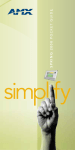
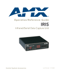
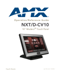
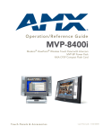
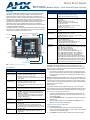
Quick Start Guide
MVP-8400i
Modero Wireless Touch Panel w/Duplex Intercom
Overview
MVP-8400i Specifications (Cont.)
The AMX MVP-8400i panel (FG5965-04) uses an internal wireless compact
flash card to communicate with a NetLinx Master via a standard 802.11g
Wireless Access Point. Panel to panel communication is enabled via a full
duplex VoIP intercom interface. The MVP-8400i utilizes a 8.4" Color Active LCD
to display a 800 x 600 pixel image using over 256 K colors, and features
programmable firmware that can be upgraded via either the wireless card or the
mini-USB port. The MVP-8400i also features nine programmable external
pushbuttons and two sets of programmable LEDs. On the 4 available IR
channels, this panel utilizes both AMX IR frequencies (38 KHz or 455 KHz) and
2 additional user-defined IR libraries.
Weight:
• Panel (no batteries): 1.85 lbs (0.84 kg)
• Panel with one battery: 2.25 lbs (1.02 kg)
• Panel with two batteries: 2.65 lbs (1.20 kg)
Screen Properties:
• Screen resolution: 800 x 600 pixels (HV) @ 60 Hz frame
frequency
• Aspect ratio: 4 x 3
• Brightness (luminance): 180 cd/m2
• Channel transparency: 8-bit Alpha blending
• Contrast ratio: 350:1
• Display colors: 256K colors (18-bit color depth)
• Dot/pixel pitch: 0.21 mm
• Panel type: TFT Color Active-Matrix
Viewing Angle:
• Vertical: + 60° (up from center) and - 40° (down from
center)
Operating/Storage
Environments:
•
•
•
•
Included
Accessories
• Wireless Interface Compact Flash card (CF Type 1)
(pre-installed into MVP)
• PS4.4 Power Supply (FG423-44)
• Stylus (pre-installed onto the left side of the unit)
• Two MVP-BP Power Packs (FG5965-20)
Other AMX
Equipment:
•
•
•
•
•
•
•
•
•
•
For detailed installation, configuration, programming, file transfer, and operating
instructions refer to the MVP-8400i Modero ViewPoint Touch Panels operation/
reference guide, available on-line at www.amx.com.
Directional pad w/center select button
Microphone
Pushbuttons (4)
Mini-USB
connector
Stylus
C
C
Speaker
Speaker
Docking station interface connector
Speaker
Power connector
FIG. 1 MVP-8400i Touch Panel components
Specifications
MVP-8400i Specifications (FG5965-04)
Power Requirement Panel while charging batteries:
(while charging):
• Constant current draw: 3.3 A @ 12 VDC
• Startup current draw: 3.9 A @ 12 VDC
• If panel is mounted onto a TDS or WDS, add 0.1 A to the
above figures.
Minimum power
supply required:
PS4.4 Power Supply (FG423-45)
- All MVP models are shipped with this power supply.
Power Modes:
• ON: Panel is fully functional.
• STANDBY: Panel uses low power, the LCD/backlight is
shutdown, LEDs still function. Panel resumes the ON
mode in ~ 1 second.
• OFF: On-board programs not running, touch screen still
powered, LED not functional. Panel resumes the ON
mode in ~ 30 seconds.
Certifications:
• FCC Part 15 Class B and CE
• IEC60950
Battery Duration:
(using 2 batteries)
• Eight hours of normal use (25% On state, 25% Standby,
and 50% Off).
• Four hours of continuous use (continuous On state).
The MVP-8400i ships with two MVP-BP batteries. You must
use both batteries to obtain the duration times given above.
Memory:
• 128 MB SDRAM
• 128 MB Compact Flash (upgradable to 1 GB) - factory
programmed
CB-MVPWDS Conduit Box (FG037-10)
CC-USB Type A to mini-B programming cable (FG10-5965)
MVP-BP battery (FG5965-20)
MVP-KS Kickstand (FG5965-12)
MVP-STYLUS three pack (FG5965-30)
MVP-TDS Table Top Docking Station (FG5965-10)
MVP-WDS Wall Docking Station - Black (FG5965-11)
MVP-WDS Wall Docking Station - Silver (FG5965-21)
MVP-WDS-SK Silver Conversion Kit (FG5965-22)
Upgrade Compact Flash (pre-programmed with firmware):
NXA-84CF128M 128 MB compact flash card (FG2116-50)
NXA-84CF256M 256 MB compact flash card (FG2116-51)
NXA-84CF512M 512 MB compact flash card (FG2116-52)
NXA-84CF1GB 1 GB compact flash card (FG2116-53)
Connections and Wiring
The PS4.4 Power Supply (with barrel connector) provides power to the
MVP-8400i either directly (via the power connector located on the lower rightside of the panel) or indirectly (by routing incoming power through the Docking
Station’s MVP Interface Connector).
•
Dimensions (HWD): • 7.17" x 10.47" x 1.34" (18.20 cm x 26.60 cm x 3.40 cm)
Power Requirement Panel with batteries fully charged or with no batteries:
(without charging): • Constant current draw: 1.3 A @ 12 VDC
• Startup current draw: 1.9 A @ 12 VDC
• If panel is mounted onto a TDS or WDS, add 0.1 A to the
above figures.
Operating Temperature: 0° C (32° F) to 40° C (104° F)
Operating Humidity: 20% - 85% RH
Storage Temperature: -20° C (-4° F) to 60° C (140° F)
Storage Humidity: 5% - 85% RH
Once the MVP is connected to a docking station; charging priority is first
given to any MVP-BP battery packs found within the MVP-8400i and then
to any other batteries inserted into the docking station’s battery charging
compartments.
Warning: Although firmware upgrades can be done over wireless Ethernet; it is
strongly recommended that firmware KIT files be transferred over a direct USB
connection and only when the panel is connected to a power supply. If battery
power or wireless connection fails during a firmware upgrade, the panel flash file
system may become corrupted.
Setup Pages
The panel is equipped with setup pages that allow you to set and configure
various features on the panel. Consult the MVP-8400i Modero ViewPoint Touch
Panels operation/reference guide for detailed information on the Setup pages.
Accessing The Protected Setup Page
1.
2.
3.
Press down and hold both the bottom, left pushbutton and down on the
directional pad (indicated in FIG. 1) simultaneously for 3-5 seconds. This
opens the Setup page.
Press Protected Setup button on the Setup page. This opens a keypad for
password entry.
Enter the panel password into the keypad (default is 1988) and select
Done to access the Protected Setup page.
Setting the Panel’s Device Number
In the Protected Setup page:
1.
2.
Press the Device Number field to open the Device Number keypad.
Enter a unique Device Number assignment for the panel, and press Done
to return to the Protected Setup page.
Press Reboot to reboot the panel, and apply the new Device Number.
Configuring the Panel’s Wireless IP Settings
The first step is to configure the wireless communication parameters, this only
configures the card to communicate to a target WAP, it is still necessary to tell
the panel which Master it should be communicating with; see Master
Connection.
If you have enabled password security on your master you need to set the
username and password within the device.
Wireless Communication Using a DHCP Address
6.
7.
8.
9.
10.
11.
In the Protected Setup page:
Touch Panel Calibration
1.
In the Protected Setup page, follow these steps:
Consult the MVP-8400i Modero ViewPoint Touch Panels operation/reference
guide for setting the wireless communication using a static IP address.
2.
Select Wireless Settings. Wireless communication is set within the IP
Settings section of this page.
Toggle the DHCP/Static field (from the IP Settings section) until the
choice cycles to DHCP. This action causes all fields in the IP Settings
section (other than Host Name) to be greyed-out.
Do not alter any of these remaining greyed-out fields in the IP Settings section.
Once the panel is rebooted, these values are obtained by the unit and
displayed in the DNS fields after power-up.
Consult the MVP-8400i Modero ViewPoint Touch Panels operation/reference
guide for setting a Host Name.
Configuring the Card’s Wireless Settings
This section configures both the communication and security parameters from
the internal wireless card to the WAP.
Once you have set up the wireless card parameters, you must configure the
communication parameters for the target Master; see Master Connection.
Consult the MVP-8400i Modero ViewPoint Touch Panels operation/reference
guide for configuring the wireless card for unsecured access to the WAP.
Configuring The Wireless Card for Secured Access To the WAP
1.
2.
Select the blank field Username to open the keyboard.
Set your Username and select Done.
Select the blank field Password to open the keyboard.
Set your Password and select Done.
Press the Back button to return to the Protected Setup page.
Press the Reboot button to reboot device and confirm changes.
Select Calibrate.
Touch each target on the screen as they appear. Once calibrated the
panel confirms and instructs you to touch the screen to continue.
Panel Intercom Configuration
Incorporating an intercom capable panel into your NetLinx
system
Download the module for the intercom panel from www.amx.com, and include
it in your NetLinx project file. For searching purposes, the module manufacturer
is AMX and the model is Intercom.
Note: The intercom module will only work with AMX intercom capable panels.
Advanced Setup
The intercom’s advanced setup pages are accessed through the intercom
setup pages. The advanced pages allow you to set the panel intercom to be
monitored, to monitor other intercom panels, and to name the panel. It is
important to name the intercom panel, the name is displayed in other panels’
intercom call directory pages.
In the Protected Setup page:
Consult the MVP-8400i Modero ViewPoint Touch Panels operation/reference
guide for more intercom setup features.
1.
2.
1.
2.
3.
4.
Select Wireless Settings.
Enter the SSID information automatically by pressing the Site Survey
button.
Select a WEP secured WAP from within the Site Survey page, and press
the Connect button.
Write down the SSID name, Current Key string value, and panel MAC
Address information so you can later enter it into the appropriate WAP
dialog fields in order to "sync-up" the secure connection. These values
must be identically reproduced on the target WAP.
Consult the MVP-8400i Modero ViewPoint Touch Panels operation/reference
guide for manually entering the SSID information.
Master Connection
The panel requires you establish the type of connection you want made
between it and your master. In the Protected Setup page:
1.
2.
3.
Select System Settings
Select Type to toggle between USB and Ethernet.
When using Ethernet, press the listed Mode to toggle through the
available connection modes:
Connection Modes
Mode Description
Procedures
Auto
The device connects to the first
master that responds. This
setting requires you set the
System Number.
Setting the System Number:
1. Select the System Number to open the
keypad.
2. Set your System Number select Done.
URL
The device connects to the
specific IP of a master via a
TCP connection. This setting
requires you set the Master’s
IP.
Setting the Master IP:
1. Select the Master IP number to the
keyboard.
2. Set your Master IP and select Done.
Listen The device "listens" for the
master to initiate contact. This
setting requires you provide
the master with the device’s IP.
4.
5.
Confirm device IP is on the Master URL
list. You can set the Host Name on the
device and use it to locate the device on
the master. Host Name is particularly
useful in the DHCP scenario where the IP
address can change.
Select the Setup button on your intercom page.
On the intercom setup page, press Advanced Setup. This launches the
password numeric keypad.
Enter the password and press Done. The default password is Password 4
of the panel’s firmware Password Setup.
3.
Naming a Panel
In the intercom Advanced Setup page:
1.
Press in the area under Panel Name. This launches an on screen
keyboard.
Type the name of the panel and press Done. This is the name that is
displayed in other panels’ intercom call directory pages.
Press Back to return to the intercom setup pages.
Press Exit when you are finished.
2.
3.
4.
Note: The Panel Name is also the G4 Web Control Name and can be set via
the panel’s firmware pages.
Related Documents
•
•
•
•
•
•
•
MVP-8400i Modero ViewPoint Touch Panels operation/reference guide
MVP-TDS Table Docking Station operation/reference guide
MVP-WDS Wall Docking Station operation/reference guide
MVP-KS KickStand operation/reference guide
VisualArchitect operation/reference guide
G4 PanelBuilder operation/reference guide
TPDesign4 Touch Panel Design Program operation/reference guide
Caution: There are particular operations, such as upgrading the NXA-CFSP
compact flash card and replacing/installing the NXA-WC80211GCF Wireless
Compact Flash Card, that require opening the MVP’s outer housing to access
internal components (as described in the MVP-7500 Modero ViewPoint Touch
Panels Operation/Reference Guide).
When opening the MVP panel housing to access internal components, be
careful not to damage or disconnect the wireless compact flash card
antenna, which is mounted to the inside of the rear housing.
Select the Master Port Number to open the keypad and change this
value. The default setting for the port is 1319.
Set your Master Port and select Done.
For full warranty information, refer to the AMX Instruction Manual(s) associated with your Product(s).
12/07
©2007 AMX. All rights reserved. AMX and the AMX logo are registered trademarks of AMX.
AMX reserves the right to alter specifications without notice at any time.
3000 RESEARCH DRIVE, RICHARDSON, TX 75082 • 800.222.0193 • fax 469.624.7153 • technical support 800.932.6993 • www.amx.com
93-5965-22
REV: C