1
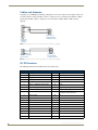
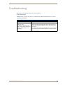
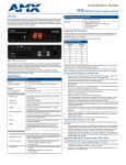
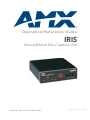
Operation/Reference Guide
IRIS
Infrared/Serial Data Capture Unit
Control System Accessories
Last Revised: 1/17/2007
AMX Limited Warranty and Disclaimer
All products returned to AMX require a Return Material Authorization (RMA) number. The RMA number is
obtained from the AMX RMA Department. The RMA number must be clearly marked on the outside of each
box. The RMA is valid for a 30-day period. After the 30-day period the RMA will be cancelled. Any shipments
received not consistent with the RMA, or after the RMA is cancelled, will be refused. AMX is not responsible
for products returned without a valid RMA number.
Warranty Repair Policy
•
AMX will repair any defect due to material or workmanship issues during the applicable warranty period at no cost to the AMX
Authorized Partner., provided that the AMX Authorized Partner is responsible for in-bound freight and AMX is responsible for
out-bound ground freight expenses.
•
The AMX Authorized Partner must contact AMX Technical Support to validate the failure before pursuing this service.
•
AMX will complete the repair and ship the product within five (5) business days after receipt of the product by AMX. The AMX
Authorized Partner will be notified if repair cannot be completed within five (5) business days.
•
Products repaired will carry a ninety (90) day warranty or the balance of the remaining warranty, whichever is greater.
•
Products that are returned and exhibit signs of damage or unauthorized use will be processed under the Non-Warranty Repair
Policy.
•
AMX will continue to provide Warranty Repair Services for products discontinued or replaced by a Product Discontinuance
Notice.
Non-Warranty Repair Policy
•
Products that do not qualify to be repaired under the Warranty Repair Policy due to age of the product or Condition of the product may be repaired utilizing this service.
•
The AMX Authorized Partner must contact AMX Technical Support to validate the failure before pursuing this service.
•
Non-warranty repair is a billable service.
•
Products repaired under this policy will carry a ninety (90) day warranty on material and labor.
•
AMX will notify the AMX Authorized Partner with the cost of repair, if cost is greater than the Standard Repair Fee, within five (5)
days of receipt.
•
The AMX Authorized Partner must provide a Purchase Order or credit card number within five (5) days of notification, or the
product will be returned to the AMX Authorized Partner.
•
The AMX Authorized Partner will be responsible for in-bound and out-bound freight expenses.
•
Products will be repaired within ten (10) business days after AMX Authorized Partner approval is obtained.
•
Non-repairable products will be returned to the AMX Authorized Partner with an explanation.
•
See AMX Non-Warranty Repair Price List for minimum and Standard Repair Fees and policies.
Table of Contents
Table of Contents
IRIS Infrared/Serial Data Capture Unit ................................................................1
Overview .................................................................................................................. 1
Specifications............................................................................................................ 1
Front and Rear Panel Components ........................................................................... 2
Using the IRIS .....................................................................................................3
Capturing HC Functions............................................................................................ 3
Capturing HC functions in default mode ......................................................................... 3
Capturing HC functions in SP mode ................................................................................ 4
Capturing difficult HC functions using P3-P8 modes....................................................... 4
Display Characters and P Mode Settings .................................................................. 4
Baud Rate Settings ................................................................................................... 5
Cables and Adapters ................................................................................................ 6
HC IR Functions ........................................................................................................ 6
Troubleshooting .................................................................................................9
E1 or ER messages .......................................................................................................... 9
IRIS Infrared/Serial Data Capture Unit
i
Table of Contents
ii
IRIS Infrared/Serial Data Capture Unit
IRIS Infrared/Serial Data Capture Unit
IRIS Infrared/Serial Data Capture Unit
Overview
The IRIS Infrared Capture Unit (FG5448) is a stand-alone, self contained unit used to capture infrared
(IR) or wired-IR function signals from a hand-held remote controller. Hand controllers (HCs) are used to
control a wide variety of audiovisual equipment that includes monitors, VCRs, TVs, and CD players.
After you capture IR functions with the IRIS unit (FIG. 1 on page 2), the functions are sent to a PC
running the IREdit software program. The IREdit software program creates HC function files that are
downloaded to the AXCESS Central Controller.
For step-by-step instructions on how to use the IREdit software program, refer to the IREdit instruction
manual.
You can also the IR Capture and Management tool in AMX’s VisualArchitect
software application to capture and manage IR functions via the IRIS. Refer to the
VisualArchitect Instruction Manual and online help for details.
Specifications
IRIS (FG5448) Specifications
Power:
12 VDC @ 160 mA max.
Dimensions (HWD):
1.51" x 5.55" x 5.45" (3.84 cm x 14.10 cm x 13.84 cm)
Weight:
18.2 oz (518.2 g)
Front Panel Components:
SIGNAL LED:
Red indicator that blinks when the IRIS unit is receiving HC functions.
IR window:
captures HC functions.
READY LED:
Green indicator that lights when the IRIS unit is ready to receive HC functions.
VERIFY;
Red indicator that lights when the IRIS unit is ready to verify HC functions.
Alphanumeric display:
(2-digit) Red 7-segment alphanumeric display that shows the capture mode
and operating status.
UP:
Increments the alphanumeric display by one and lights the red LED inside the
pushbutton.
DOWN:
Decrements the display by one and lights the red LED inside the pushbutton.
SEND:
Transmits captured HC functions to a PC running the IREdit software program.
The red LED inside the pushbutton lights when valid HC functions are ready to
send.
Rear Panel Components:
12 VDC/12 VAC connector:
2-pin (male) 12 VDC or 12 VAC power supply connector.
8-pin data connector:
Captures wired-IR HC functions. Connect the HC to the IRE IN or WIRED IN
pins.
RS-232 connectors:
• DB-9 connector for data communications with a PC.
• 6-pin RJ-11 modular connector for data communications. The RJ-11
connector is only used with older SX-DCU+ products.
Control ports:
• IR sensor to receive IR codes; IR serial input for wired IR codes.
• DB-9 female connector for Axcess and PC communication.
Enclosure:
IRIS Infrared/Serial Data Capture Unit
Metal with black matte finish
1
IRIS Infrared/Serial Data Capture Unit
IRIS (FG5448) Specifications (Cont.)
Includes:
• Large, 2-digit status LED
• Adjustable RS-232 port (300 - 9600 baud)
• 12 VAC power supply
• IREdit software
Front and Rear Panel Components
IR window
Alphanumeric display
UP button
DOWN button
SIGNAL LED
SIGNAL
IR
READY
VERIFY
UP
DOWN
SEND
READY LED
SEND button
IRE
IN
WIRED
IN
12
12V
5
VERIFY LED
OUT
RS-232
RS-232
12 V connector
8-pin data
connector
RS-232 6-pin
RJ-11 connector
RS-232 DB-9
connector
FIG. 1 IRIS front and rear views
2
IRIS Infrared/Serial Data Capture Unit
Using the IRIS
Using the IRIS
Capturing HC Functions
The two modes you can use to capture HC functions are default and special function. You use default
mode, which is automatically set when you connect power to the IRIS unit, to capture the majority of HC
functions. The table below shows the IRIS unit settings for default mode. Before capturing HC
functions, make sure the baud rate in the IRIS unit is set properly, and connected to a PC running the
IREdit software application.
You can also the IR Capture and Management tool in AMX’s VisualArchitect
software application to capture and manage IR functions via the IRIS. Refer to the
VisualArchitect Instruction Manual and online help for details.
Refer to the IREdit instruction manual for information on to storing captured HC functions.
Default Mode Settings
Default
Setting
Baud
9600
P3
off
P4
on
P5
off
P6
on
P7
on
P8
off
Capturing HC functions in default mode
To capture HC functions in default mode:
1. Make a list of the name and sequence of the HC functions you want to capture. The standard order
for HC functions is listed in theHC IR Functions section on page 6.
2. Connect the RS-232 cable to the DB-9 connector on the IRIS unit and the RS-232 port on your PC,
as shown in theCables and Adapters section on page 6. Set the baud rate in the IRIS unit to match
the PC baud rate. Refer to theBaud Rate Settings section on page 5 to set the baud rate. Then,
connect the 12 VDC or 12 VAC power supply to the 12 VDC connector on the IRIS unit. The READY
LED lights and 01 appears in the display.
3. Hold the HC device approximately 3-inches away from the IR capture window. Press and hold the
first key on the HC to capture the first function. The SIGNAL LED will start blinking. Release the HC
key as soon as the READY LED goes off.
4. The [ ] briefly appears in the display to indicate the HC function is captured. Then, 01 appears and
the READY and VERIFY LEDs light. The LED will not light if P4 mode is active; refer to theDisplay
Characters and P Modes table on page 4 for further information.
5. Hold the HC device approximately 3-inches away from the IR capture window. Press and hold the
same key on the HC device again to verify the IR function was captured correctly by the IRIS unit. If
the HC function is captured correctly, a pair of [ ] (brackets) will briefly flash in the display. The
VERIFY LED goes off, 01 appears in the display, and the SEND pushbutton's LED lights. If an Er
message appears in the display, repeat steps 3 and 5. Otherwise, go to step 6.
IRIS Infrared/Serial Data Capture Unit
3
Using the IRIS
6. Press the SEND pushbutton to send the captured HC function to the PC running the IREdit software
program.
7. Repeat steps 3 through 6 to capture all the HC functions on your list.
Capturing HC functions in SP mode
If you cannot capture an HC function in default mode, set the IRIS unit to special function (SP) mode.
Perform these steps to capture HC functions in SP mode:
1. Press and release the UP and SEND pushbuttons at the same time. The message SP briefly appears in
the display and the UP LED lights. The IRIS unit is now in SP mode.
2. Perform the Capturing HC functions in default mode steps 3 through 6 four times, or until the SEND
LED lights, to capture the HC function. Then, go to the next step.
3. Simultaneously press and release the UP and SEND pushbuttons to reset the IRIS unit to default
mode. The message nO (normal operation) briefly appears in the display to indicate default mode is
active.
All settings are returned to their default state when power is removed from the unit.
Capturing difficult HC functions using P3-P8 modes
Set the IRIS unit to the P3-P8 modes if you cannot capture an HC function in default or SP mode, The P3
and P4 modes are special settings to capture HC functions. Perform these steps to capture HC functions
using P3-P8 modes:
1. Simultaneously press and release the UP, DOWN, and SEND pushbuttons. The message P1 appears in
the display. The IRIS unit is now in P mode.
2. Use the UP or DOWN pushbutton to select the appropriate P modes according to the descriptions in
the following table.
3. Simultaneously press and release the UP, DOWN, and SEND pushbuttons to toggle the P mode setting
On and Off. The display then shows an On or Off message indicating the new P mode setting and
then immediately exits the P mode. You can activate multiple P modes to capture an HC function;
refer to theDefault Mode Settings table on page 3 for the P mode default settings when you connect
power to the IRIS unit.
4. Repeat the Capturing HC functions in default mode steps 3 through 6, on page 3, to capture the HC
function.
Display Characters and P Mode Settings
The following table lists the display characters and P mode settings for special HC devices.
Display Characters and P Modes
Characters Description
4
[]
HC function is captured, analyzed, stored, and verified.
Er
Error: HC function did not verify correctly.
Nd
No Device. Communication device error detected, or the IREdit program is not staged to
receive HC functions.
NO
Normal Operation. Ready to capture HC.
OF
P mode is off.
IRIS Infrared/Serial Data Capture Unit
Using the IRIS
Display Characters and P Modes (Cont.)
Characters Description
On
P mode is on.
So
Send OK. HC function sent without errors to a PC running IREdit.
SP
Special Function. Special mode to capture unusual HC functions.
P1-P2
Not used.
P3
Sends HC functions to a PC running IREdit automatically after the VERIFY operation.
P4
Disables the VERIFY operation to capture HC functions. Default mode requires the VERIFY
operation.
P5
Loose-timing mode to capture JVC (PQ10956) HC functions.
P6
Glitch-detection mode to capture Kinderman and some Mitsubishi HC functions.
P7
Disables glitch-detection mode to capture non-carrier HC functions.
P8
Strict-timing mode
Baud Rate Settings
The default communication setting for the IRIS unit is 9600 baud. You can change the baud rate with the
UP, DOWN, and SEND pushbuttons. You must set the IRIS unit's baud rate to match the baud rate of the PC
running the IREdit software program to store HC functions.
The IRIS unit automatically sets the baud rate to 9600 when you connect power. If
you reset the baud to any other setting and disconnect power, the previous baud rate
setting is lost and the IRIS unit will default back to 9600 baud.
To set the baud rate:
1. Disconnect the power supply from the IRIS unit.
2. Press and hold the UP, DOWN, and SEND pushbuttons. Reconnect the power supply and release the
pushbuttons.
3. The two digits that appear in the display represent the current baud rate setting. The following table
lists the RS-232 baud rates and corresponding display digits.
Baud Rate and Display Digits
Baud Rate
Display Digits
300
03
600
06
1200
12
2400
24
4800
48
9600
96
4. Press the UP or DOWN pushbuttons to reset the baud rate.
5. Press and hold the UP, DOWN, and SEND pushbuttons again to set the new baud rate. The READY LED
lights to indicate the IRIS unit is ready to capture an HC function.
IRIS Infrared/Serial Data Capture Unit
5
Using the IRIS
Cables and Adapters
Depending on your IREdit programming configuration, one or more cables may be required. Connectors
are shown from the wiring side. FIG. 1 shows a computer-to-Axcess Control System (DB-25 to DB-9)
wiring diagram; FIG. 2 shows a computer-to-Axcess Central Controller (DB-9-to-DB-9) wiring
diagram.
2
3
5
3
2
7
9-pin Axcess
Control System
or IRIS connector
25-pin PC
serial-port
connector
FIG. 1 Computer-to-Axcess Control System (DB-25 to DB-9) wiring diagram
5
3
2
2
3
5
9-pin PC serial-port
port connector
9-pin Axcess
Control System
or IRIS connector
FIG. 2 Computer-to-Axcess Control System (DB-25 to DB-9) wiring diagram
HC IR Functions
The following table lists the HC IR functions in standard order.
HC IR Functions - Standard Order
Function
6
Description
Function
Description
1
Play >
22
Channel up or +
2
Stop [ ]
23
Channel down or -
3
Pause | | or still
24
Volume up or +
4
Ffwd >> (AMS/skip track/chapter)
25
Volume down or -
5
Rewind << (AMS/skip track/chapter)
26
Mute
6
Search fwd >>| (AMS/scan)
27
On (power typically)
7
Search rev |<< (AMS/scan)
28
Off (power typically)
8
Record
29
TV/Video or TV/VCR or TV/LDP
(one button source selection)
9
Power or on/off
30
TV
10
’0’ or ’10’
31
Video1, Line A, VCR1, VDP, or input +
11
’1’ (channel digits or tracks for CD)
32
Video2, Line B, VCR2, or input -
12
’2’
33
Video3
13
’3’
34
RGB1 or Tape1
14
’4’
35
RGB2 or Tape2
15
’5’
36
CD
16
’6’
37
Tuner
17
’7’
38
Phono
18
’8’
39
Aux
IRIS Infrared/Serial Data Capture Unit
Using the IRIS
HC IR Functions - Standard Order (Cont.)
Function
Description
Function
Description
19
’9’
40
AM/FM
20
’+10’ or ’+100’
41
Play < (play reverse)
21
Enter (used in conjunction with
number typically)
42
A/B
IRIS Infrared/Serial Data Capture Unit
7
Using the IRIS
8
IRIS Infrared/Serial Data Capture Unit
Troubleshooting
Troubleshooting
This section provides product solutions to common problems.
E1 or ER messages
The Er/E1 message appears when there is a communication problem with the PC and not an error in
capturing the IR functions.
E1 or Er Messages
Problem
Solution:
• Using NetLinx Studio: Go into the Device Manager dialog box and
change the COM port settings. Verify that the new settings are as
follows: 9600, No Parity, 8 data bits, 1 stop bit, and Flow Control is
The AXB-IRIS is able to verify the
set to None.
codes, but when the Send Command
• Using IREdit: This program is recommended for use with this product
is pressed, an Er appears on the
and can also be used if the Studio application changes (mentioned
unit’s display.
above) do not work.
A Hand Control can’t seem to
capture the codes.
IRIS Infrared/Serial Data Capture Unit
9
Troubleshooting
10
IRIS Infrared/Serial Data Capture Unit
Troubleshooting
IRIS Infrared/Serial Data Capture Unit
11
AMX. All rights reserved. AMX and the AMX logo are registered trademarks of AMX. AMX reserves the right to alter specifications without notice at any time.
©2007
1/07
It’s Your World - Take Control™
3000 RESEARCH DRIVE, RICHARDSON, TX 75082 USA • 800.222.0193 • 469.624.8000 • 469-624-7153 fax • 800.932.6993 technical support • www.amx.com