1
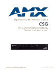
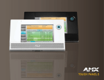
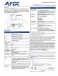
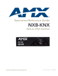
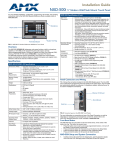
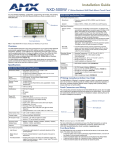
Installation Guide
CSG SIP Communications Gateway (CSG-500/544/580)
ATTENTION: READ THIS FIRST!
CSG Specifications (continued)
For more detailed installation, configuration, programming, and operating
instructions, refer to the CSG SIP Communications Gateway Instruction Manual
available on-line at www.amx.com.
Included
Accessories
• PSN3.0, Power Supply, 3.0A, 12.0CVD (FG423-31)
• CSG SIP Communications Gateway Installation Guide
(93-2182-01)
• 2 Surface mounting brackets (62-2182-04)
• 4 #4-40 X .250 PPH screws (80-0112)
Other AMX
Equipment
• DIN Rail Mounting Bracket (FG532-06)
FIG. 1 CSG SIP Communications Gateway (displaying CSG-544)
Overview
The CSG SIP Communications Gateway (FIG. 1) is a stand alone Private Branch
Exchange (PBX) which runs a version of Asterisk. The CSG can function not
only as a PBX, but also as VoIP ATA, or VoIP gateway. It has eight analog ports
that can be configured (via modules) as Foreign Exchange Office (FXO) or
Foreign Exchange Station (FXS) ports.
The CSG enables you to transform an intercom-enabled Modero Touch Panel
into a full-featured IP phone. With the CSG and an intercom-enabled Modero
Touch Panel you can make and receive local, long distance, and international
phone calls, and have access to phone features like call waiting, caller ID, call
forwarding, call queuing, and voice mail. The CSG supports AMX Session
Initiated Protocol (SIP)-enabled touch panels, such as the MVP-8400i,
NXD-1000Vi, and NXD-700Vi, as well as 3rd party IP phones.
Installing the Hardware
CAUTION!
To reduce the risk of fire, use only No. 26 AWG or larger
telecommunication wiring for network connections.
1.
2.
3.
Note: The analog port configuration is selected when you purchase your CSG
unit.
4.
Specifications
CSG Specifications
Connect an Ethernet cable to the Network port.
Connect the provided power supply to the unit’s DC connector. The unit
immediately receives power once you connect a power source to it.
When the unit completes the boot process, the left-most eight LEDs
indicate how the analog ports are configured. A red light indicates the port
is FXO, and a green light indicates the port is FXS. If the light for a port is
off, the port is not installed.
Connect telephones to the analog ports that are configured as FXS ports
and connect phone lines to the analog ports that are configured as FXO
ports. If you are using the CSG-500, you can skip this step.
WARNING!
If you are using the CSG-544, do NOT connect analog ports 1-4 to
a phone line. Since both the FXS port and the phone line supply
power, the hardware could sustain damage. This damage is not
covered under the AMX standard warranty.
Dimensions
1.74” x 11.45” x 5.44” (4.41 cm x 29.09 cm x 13.82 cm)
Weight
2.25 lbs. (1.02 kg)
Enclosure
Metal with black matte finish
Power
Requirements
Constant current draw: 2.6 A @ 12 VDC
Instructions for Wall Mounting
Memory
• 8MB on board serial Flash memory
• 64MB 16-bit parallel SDRAM
1.
Certifications
FCC (Class A), CE, IEC60950, and RoHS
Operating/
Storage
Environment
•
•
•
•
Operating Temperature: 0° C (32° F) to 40° C (104° F)
Operating Humidity: 5% to 85% RH Non-Condensing
Storage Temperature: -20° C (-4° F) to 70° C (158° F)
Storage Humidity: 0% to 85% RH Non-Condensing
2.
3.
4.
Front Panel Components:
Power LED
Indicates whether the unit is turned on and receiving power.
Network LED
Indicates whether a network cable is connected and the speed of
the network.
IP Phones
LEDs
Indicates whether the corresponding link is connected and the
speed of the link.
Analog LEDs
Indicates whether the analog port is installed and the type of port
(FXO/FXS) installed. (Not available on all models.)
5.
Select the area to mount the CSG unit. The unit should be mounted at or
below eye level to properly view the LEDs.
Line up one of the surface mounting brackets with the two holes on one
side of the CSG. Install two #4-40 X .250 PPH screws into the holes in the
bracket to secure the bracket to the CSG.
Repeat step 2 to attach the second bracket to the other side of the unit.
Affix one screw to the wall. Leave approximately 1/4-inch of the screw
protruding from the wall to allow the head of the screw to slide into the
settings on the mounting bracket, mounting the unit to the wall.
Repeat step 4 to attach the second bracket to the wall.
Understanding the LEDs
There are 14 LEDs on the front panel of the CSG. The eight LEDs corresponding
to the analog ports on the rear panel indicate the type of interface installed. The
following table explains the definition of each LED and its color representation:
LED Definitions
Rear Panel Components:
LED
Color
Description
Power
connector
5.1mm OD, 2.1mm pin, 12V 3.0A center positive
Power
Blue (pulsing)
Configuration
Reset Switch
Resets the current configuration to the factory default when
pressed continuously during the boot process.
On when the unit boots up after the bootload process
has completed. The LED pulses at a rate which is
proportional to the BlackFin processor load.
Network Off
Console port
1 RJ45 port for console (craft) port serial control
Network port
1 RJ45 10/100baseT port for a general (WAN) connection
IP Phones
ports
4 RJ45 10/100baseT ports for IP phone connections
Analog ports
• 8 RJ11 ports: 4 for FXO and 4 for FXS connections (CSG-544
only)
• 8 RJ11 ports for FXO connections (CSG-580 only)
Note: The CSG-500 does not use analog ports.
No line is connected or the interface is inactive.
Green
(flashing)
Link is up at 100Mbps. LED flashes at 1/10 second
intervals as traffic is detected.
Red (flashing)
Link is up at 10Mbps. LED flashes at 1/10 second
intervals as traffic is detected.
IP
Off
Phones
(4 ports) Green
(flashing)
Red (flashing)
No line is connected or the interface is inactive.
Link is up at 100Mbps. LED flashes at 1/10 second
intervals as traffic is detected.
Link is up at 10Mbps. LED flashes at 1/10 second
intervals as traffic is detected.
Setting Up Your Touch Panel to Work with Your CSG
LED Definitions (continued)
Analog Off
(8 ports)
Green (solid)
No analog port is installed in the corresponding port.
Port is configured for FXS operation and is enabled.
An analog telephone may be connected to this port.
Green
(flashing)
Telephone is ringing.
Green (slow
blinking)
Telephone is in use.
Red (solid)
Port is configured for FXO operation and is enabled.
A telephone line may be connected to this port.
Red (flashing)
Telephone line is ringing.
Red (slow
blinking)
Telephone line is in use.
Follow these steps to configure your touch panel to work with the CSG:
1.
2.
3.
From the main Setup page on your touch panel, press Protected Setup.
The Protected Setup page opens.
Press Other Settings. A slide out menu appears.
Press SIP. The SIP Settings page opens (FIG. 2).
Setting Up Your System
The CSG comes with a user interface framework which gives you the ability to
configure it through an easy to use interface. To access the interface, you will
need the IP address your CSG server is using. Once you have the IP address,
you can configure your CSG via a web browser.
The user interface included as part of the CSG implementation provided with
the CSG gives you the ability to set up a telephone system without the need to
use command line configuration. The user interface opens on the main menu,
which gives you the ability to add features or further modify an existing
configurations. The following sections provide information about procedures
you may want to perform when you are getting started.
Logging on to the Server for the First Time
Connect a computer to the LAN IP Phone port on the CSG with an Ethernet
cable. In the address field of a web browser, enter the default IP address of
http://192.168.69.1. To log on to the system, enter the following user name and
password:
•
•
Username: admin
Password: 1988
Subsequent Logons to the CSG
The method described above will work to log onto the configuration tool of the
CSG. In addition, you can log onto the CSG using the CSG's Network port once
it has been enabled. In this case, open a web browser on a computer which is
located on the same network as the CSG. In the address field of the web
browser, enter the IP address of the CSG as defined during the initial
installation.
Changing Your Network Configuration
DHCP is automatically enabled for Wide-Area Networks (WAN) by default. If
you need to change your network configuration—like set a static IP address,
for example—the Networking Configuration page enables you to make any
necessary changes. Follow these steps to change your network configuration:
1.
2.
3.
4.
FIG. 2 SIP Settings page
4.
5.
6.
7.
8.
9.
10.
In the Proxy Address field, enter the IP address or DNS name of the
server you want to access. The IP address depends on whether you
connect the touch panel to one of the IP Phone ports or through the LAN
with the CSG.
In the Port Number field, enter the port number of the server you want to
access. The default port number is 5060.
In the User Name field, enter a user name you can use for authentication
to the server. Normally, the user name is the same as the phone number
assigned to the extension you are using.
In the Password field, enter the password for the user name.
Press Enable to have your panel read the configuration and attempt to
connect to the proxy server.
Press Save.
Press Back to return to the previous page.
Compatible Devices
The following list describes all SIP-enabled touch panels that are compatible
with the CSG.
• MVP-8400i
• NXD-700Vi
• NXD-1000Vi
The firmware for these panels must be up-to-date to use SIP.
Select Network | Main from the System tab.
Enter the host name for your server.
Click the WAN Network tab. You can use the options on this tab to
establish the settings that enable you to connect to the Internet, or to an
internal, private network.
Ensure the DHCP check box is checked.
Note: If you have difficulty obtaining an IP address dynamically, clear the
DHCP check box and specify the IP address, subnet, gateway, and DNS
settings. This information should be available from your network administrator
or Internet Service Provider (ISP).
5.
6.
7.
8.
9.
Click the IP Phones tab. You can use the options on this tab to establish
settings to access your CSG.
Enter the IP address, subnet, or any other appropriate information
necessary to access your CSG.
Click the Timezones tab.
Select a time zone from the provided drop-down combo box.
Click Accept.
For full warranty information, refer to the AMX Instruction Manual(s) associated with your Product(s).
7/08
©2008 AMX. All rights reserved. AMX and the AMX logo are registered trademarks of AMX.
AMX reserves the right to alter specifications without notice at any time.
3000 RESEARCH DRIVE, RICHARDSON, TX 75082 • 800.222.0193 • fax 469.624.7153 • technical support 800.932.6993 • www.amx.com
93-2182-01
REV: D