1
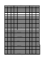
Assembly Instructions AC-30 Audio Cassette Interface
Introduction
Cassette tape is one of the most flexible and least expensive means of mass
data storage for computer systems. When compared to paper tape readers and punches,
you'll find that although the paper tape readers can be made rather inexpensively,
the punches cannot. Paper tape systems are typically slower and the punched tapes
cannot of course be repunched and used over and over again, as you can with
cassettes. Disk systems on the other hand offer significant advantages over
cassettes but are still too expensive for many applications, and for most
hobbyists. Even those lucky enough to have a disk system still need a more
universal medium for exchanging programs.
Although there are several commercial digital cassette tape decks on the
market today, recording techniques vary and they are of course much more expensive
than the average audio cassette unit. As could be expected most hobbyist computer
system mass data storage designs have been based on the audio cassette recorder.
The use of inconsistent recording techniques among the various manufacturers
makes it impossible for example to record a program, or data tape on a SWTPC 6800
Computer System and play it back on a MITS 680 Computer System. In order to
coordinate manufacturer design efforts, and exploit the most effective recording
technique, BYTE Magazine of Peterborough, New Hampshire, 03458 held a symposium in
the Fall of 1975 in Kansas City in an attempt to establish a recording standard for
the storage of digital data on audio cassette recorders. The standard which was
adopted has been tested and fully supported by Southwest Technical Products
Corporation. It appears to be the best compromise between economy and reliability.
Although complete details are contained in the Feb., 1976 issue of BYTE Magazine,
the recording philosophy is to record data serially using the standard UART format
at 300 baud (30 characters/second). Marks or logic ones are represented by
recording a 2400 Hz sine wave on the tape while spaces or logic zeroes are
represented by recording a 1200 Hz sine wave. With the proper circuitry this
recorded data can then be read off the tape and transposed into a self clocking
UART based tare system which will tolerate audio recorder speed variations of
approximately +30%. This figure is far better than that of most other modulation
techniques and is a real advantage when you consider the degree of worst case speed
variation between inexpensive audio recorders. In addition we have speed variations
due to line voltage, battery voltage, wow and flutter, mechanism wear, etc. Thus
evolved the "Kansas City" standard. It should be noted that the standard does not
specify how the data is to be organized on the tape, so there can, and probably
will be some incompatibility among various manufacturer's units. This is however
more of a software problem than a hardware problem and thus a little easier to
resolve.
Although the SWTPC AC-30 Audio Cassette Interface has been used extensively
with the SWTPC 6800 Computer System and CT-1024 (TV Typewriter II) Terminal System,
it has been designed to be as universal and flexible a system as possible. If your
computer's control terminal is interfaced to the computer thru 300 baud, RS-232
compatible serial interfaces with accessible UART type 16 X baud rate clocks on
both computer and terminal, the SWTPC AC-30 Cassette Interface Unit is simply
plugged between the computer and terminal interfaces. This is the ideal mode of
Scanned and edited by Michael Holley
Feb 16, 2002
Southwest Technical Products Corporation Document
Circa 1976
1
operation since the cassette unit can take full advantage of computer resident tape
load and dump routines and requires no additional interfaces. Switching the
cassette unit to the LOCAL mode directly interconnects the terminal and cassette
unit for terminal "only" cassette tape operation just like the LOCAL mode of
operation on teletypewriters. While operating in the REMOTE mode the computer
communicates with both the terminal and cassette unit, here again just like the
REMOTE mode of operation on teletypewriters. Those customers using the CT-1024 (TV
Typewriter II) Terminal System or any terminal system with accessible control
character decoders may even pick Reader ON (Control Q), Reader OFF (Control S),
Record On (Control R), and Record OFF (Control T) control commands right off the
control character decoder circuitry on their terminal system giving the computer
system program control over cassette recorder data flow and even motor operation.
Those not having access to decoded control commands may still have cassette control
by driving the cassette interface with control lines from a separate parallel
interface option located on the attached computer system.
Those users not operating their control terminal RS-232 serial at 300 baud or
not having access to their terminal's 16 X UART clock may still use the cassette
interface, but must attach it to the computer system thru a separate RS-232 serial
300 baud interface with accessible 16 X clocks located on the computer system. This
however eliminates the ability to use the computer resident control terminal tape
load and dump routines as well as the LOCAL/REMOTE feature described previously.
The cassette interface circuitry is constructed on a 7 3/4" X 7 1/2" double
sided, plated thru hole fiberglass circuit board with all electrical connections
made to the board thru one of the five edge connectors. The three connectors along
the back edge of the circuit board are for connections to the computer, control
decoder and terminal while the two along the front edge are for connections to the
cassette interface's control panel. The PC board in turn is mounted inside a 12
3/4" wide X 3" high X 11" deep aluminum chassis with dress panel and perforated
cover.
PC Board Assembly
NOTE: Since all of the holes on the PC board have been plated thru, it is
only necessary to solder the components from the bottom side of the board. The
plating provides the electrical connection from the "BOTTOM" to the "TOP" foil of
each hole. Unless otherwise noted it is important that none of the connections be
soldered until all of the components of each group have been installed on the
board. This makes it much easier to interchange components if a mistake is made
during assembly. Be sure to use a low wattage iron (not a gun) with a small tip. Do
not use acid core solder or any type of paste flux. We will not guarantee or repair
any kit on which either product has been used. Use only the solder supplied with
the kit or a 60/40 alloy resin core equivalent. Remember all of the connections are
soldered on the bottom side of the board only. The plated-thru holes provide the
electrical connection to the top foil.
2
( )
Before installing any parts on the circuit board, check both sides of the
board over carefully for incomplete etching and foil "bridges" or "breaks".
It is unlikely that you will find any but should there be one especially on
the "TOP" side of the board it will be very hard to locate and correct after
all of the components have been installed on the board.
( )
Attach all of the resistors to the board. As with all other components unless
noted, use the parts list and component layout drawing to locate each part
and install from the "TOP" side of the board bending the leads along the
"BOTTOM" side of the board and trimming so that 1/16" to 1/8" of wire
remains. Solder. You may find that there are no pads on the "BOTTOM" side of
the board for resistor R42. If not be sure its two leads are soldered from
the "TOP" side of the board.
( )
Install all of the capacitors on the board. Be sure to orient the
electrolytic capacitors correctly. The polarity is indicated on the component
layout drawing. The body of electrolytic capacitor C21 should be insulated so
as not to "short" to foil conductors under it. If the body of the capacitor
is not insulated attach the capacitor so it is up off the board about 1/8".
Solder.
( )
Starting from one end of the circuit board install each of the five Molex
female edge connectors along the edges of the board. These connectors must be
inserted from the "TOP" side of the board and must be pressed down firmly
against the board. Make sure the body of the connector seats firmly against
the circuit board and that each pin extends completely into the holes on the
circuit board.
( )
Insert the small nylon indexing plugs into the edge connector pins indicated
by the small triangular arrows on the "BOTTOM" side of the circuit board.
This prevents mating plugs from being accidentally plugged onto the board
incorrectly.
( )
Install the transistors on the board. The transistors must be turned to match
the outlines on the component layout drawing. Solder.
( )
Install all of the diodes on the board excluding diodes D18 thru D22. The
diodes must be turned to match the outlines on the component layout drawing.
Solder.
( )
Install LED diode D18 on the circuit board. Be sure the flat on the side of
the LED matches that shown on the component layout drawing. Attach the diode
so the bottom of its case is 1/8" to 1/4" above the top of the board. Solder.
( )
Install reed
polarized so
matching the
holes on the
( )
Install integrated circuit IC16 on the circuit board. This component must be
oriented so its metal face is facing the circuit board. The IC is secured to
the circuit board with a #4-40 X 1/4" screw, lockwasher and nut. The three
leads of the integrated circuit must be bent down into each of their
respective holes and trimmed. Solder.
relays RLY1 and RLY2 on the circuit board. These relays are not
they need not be oriented in any particular position other than
end with three leads and the one with just one to the respective
circuit board. Solder.
NOTE: Most of the integrated circuits used in this kit are CMOS and are
susceptible to damage by static electricity. Although some degree of protection is
provided internally within the integrated circuits, their sensitivity demands the
utmost in care. Before opening and/or installing any CMOS integrated circuits you
should ground your body and all metallic tools coming into contact with the leads,
thru a 1 M ohm 1/4 watt resistor (supplied with the kit). The ground must be an
"earth" ground such as a water pipe, and not the circuit board ground. As for the
3
connection to your body, attach a clip lead to your watch or metal ID bracelet.
Make absolutely sure you have the 1 Meg ohm resistor connected between you and the
"earth" ground, otherwise you will be creating a dangerous shock hazard. Avoid
touching the leads of the integrated circuits any more than necessary when
installing them, even if you are grounded. On those MOS IC's being soldered in
place; the tip of the soldering iron should be grounded as well (separately from
your body ground) either with or without a 1 Meg ohm resistor. Most soldering irons
having a three prong line cord plug already have a grounded tip. Static electricity
should be an important consideration in cold, dry environments. It is less of a
problem when it is warm and humid.
( )
Install integrated circuits ICI thru IC15 following the precautions given in
the preceding section. As each is installed, make sure it is down firmly
against the board before soldering all of its leads. Be very careful to
install each in its correct position. Do not bend the leads on the back side
of the board. Doing so makes it very difficult to remove the integrated
circuits should replacement ever be necessary. The "dot" on the end of the
package is used for orientation purposes and must match with that shown on
the component layout drawing for each of the IC's.
( )
Working from the "TOP" side of 'the circuit board, fill in all of the
feed-thru's with molten solder. The feed-thru's are those unused holes on the
board whose internal plating connects the "TOP" and "BOTTOM" circuit
connections. Filling these feed-thru's with molten solder guarantees the
integrity of the connections and increases the current handling capability.
( )
Now that most of the components have been installed on the board, double
check to make sure all have been installed correctly in their proper
location.
( )
Check very carefully to make sure that all connections have been soldered. It
is very easy to miss some connections when soldering which can really cause
some hard to find problems later during check out. Also look for solder
"bridges" and "cold" solder joints which are another common problem.
Since the circuit board now contains CMOS devices it is susceptible to damage
from severe static electrical sources. One should avoid handling the board any more
than necessary and when you must, avoid touching or allowing anything to come into
contact with any of the conductors on the board.
4
Parts List AC-30 Audio Cassette Interface
Resistors
R1
R2, R3, R9, R11, R12, R15
R19-R22, R27 R29, R32-R34,
R36, R40-R42, R44-R47
R4, R48, R49
R5
R6
R7, R30, R31, R35, R37, R43
R8, R17, R18, R23-R26
R10
R13, R14
R16
R38
R39
33K ohm 1/4 watt resistor
10K ohm 1/4 watt resistor
10K ohm 1/4 watt resistor
10K ohm 1/4 watt resistor
330 ohm 1/4 watt resistor
2.2K ohm l/4 watt resistor
4.7K ohm 1/4 watt resistor
470 ohm 1/4 watt resistor
100K ohm 1/4 watt resistor
330K ohm 1/4 watt resistor
22K ohm 1/4 watt resistor
20K ohm trimmer resistor
47K ohm 1/4 watt resistor
200K ohm trimmer resistor
Capacitors
C1, C6, C12-C15
C2
C3, C8
C4
C5, C18
C7, C9
C10
C11, C19, C20
C16, C22
C17
C21
C23-C25
1000 pfd capacitor
2000 pfd capacitor
O.022 mfd capacitor
1 mfd @15 VDC electrolytic capacitor
0.01 mfd capacitor
0.047 mfd capacitor
2700 pfd capacitor
470 pfd capacitor
100 mfd @16 VDC electrolytic capacitor
10 mfd @10 VDC tantalum, capacitor
1000 mfd @25 VDC electrolytic capacitor
0.1 mfd disc capacitor
Semiconductors
ICI,
IC2,
IC3,
IC4
IC6,
IC7
IC9
IC10
IC12
IC15
IC16
IC5, IC8
IC11
IC13
IC14
D1, D2, D4, D5-D11
D3
D12, D13
D14-D17
D18-D22
Q1, Q2, Q4-Q8
Q3, Q9-Q11
4013 dual D flip-flop
4001 quad NOR gate
4070 quad EX-OR gate
4558 dual op amp
4053 triple multiplexer
4049 hex buffer
4023 triple 3-input NAND gate
555 timer
1489 quad RS-232 receiver
1488 quad RS-232 transmitter
7805 5 VDC regulator
1N4148 silicon diode
4.7 volt zener diode 1N4732 or IN5230
7.5 volt zener diode 1N4737 or 1N5236
1N4003 silicon rectifier
light emitting diode
2N5210 NPN transistor
2N5087 PNP transistor
5
Misc.
RLY1, RLY2
S1-S3
S4, SS
S6, S7
T1
F1
6 VDC reed relay
DPDT miniature toggle switch
SPDT center off miniature toggle switch
SPDT miniature toggle switch
18 VAC @300 Ma. secondary 120/240 VAC
50-60 Hz primary power transformer
1 amp standard fuse
6
Chassis Assembly
( )
Sandwich the dress panel between the chassis and mounting hardware and attach
switches S1-S7 to the chassis using the wiring pictorial to show proper
location and orientation. Secure each switch using a finishing washer and
nut.
( )
Insert each of the four LED plastic mounting clips into the front panel holes
provided for LED diodes D19 thru D22. Insert each of the LED diodes into the
clips so that the flat on the side of each diode matches with that shown in
the wiring pictorial. Just for reference the side with the flat is the same
as the side with the shorter lead. Secure each LED diode with the plastic
retaining ring. This ring must be pressed on tightly to prevent the LED from
being loose.
( )
Attach RCA jacks J6 thru J9 to the chassis. Jack J6 should have a ground lug
put under it. Secure each jack with a 1/4" nut.
( )
RCA jacks J10 and J11 must be electrically insulated from the chassis. In
order to do this, first slip a shoulder washer over each RCA jack with the
shoulder against the inside of the chassis, place the jack against the
outside of the chassis, put another shoulder washer on the back side of the
jack with the shoulder against the inside of the chassis, follow this with'
the ground lug and finally secure with a 1/4" nut.
( )
Attach the power transformer to the chassis using #6-32 X 1/4" screws,
lockwashers and nuts. Orient the transformer so the end with the three wires
coming out of it is toward the front of the chassis.
( )
Attach the fuseholder to the chassis using a #6-32 X 3/8" screw, lockwasher
and nut.
( )
Snap the four nylon PC board supports into the holes provided for them in the
chassis.
( )
Snap the 1 1/2" bushing into the large hole provided on the back of the
chassis. The bushing should be installed from the outside of the chassis.
( )
Turn the chassis upside down and attach each of the four press on rubber feet
about 1" in from each of the corners.
( )
Using a pair of pliers, crimp the strain relief onto the line cord at a point
12" from the end of the cord. While compressing the strain relief insert the
12" length of the line cord and the strain relief into the 7/16" hole
provided on the back of the chassis, from the outside of the chassis.
( )
Press the specified color of switch cap onto the handle of each toggle switch
as specified below:
S1
S2
S3
S4
S5
S6
S7
( )
–
–
–
–
–
–
-
white
green
green
yellow
yellow
red
white
Snap the ten tinnerman clips onto the holes provided on the front and back
lips of the chassis.
7
Chassis Wiring
( )
A11 connections made between the components on the chassis and the printed
circuit board are made thru connectors J1 and J2. This allows one to easily
remove the PC board for service or access to the bottom side of the PC board.
When soldering the wires to the main plugs for connectors J1 and J2, the
plugs must not be plugged into the PC board. If they are the female
connectors may melt and be ruined. Follow the wiring steps outlined on the
next two pages.
( )
Note for 220 VAC Operation - To wire the
wiring steps 1 thru 4 and instead solder
BlackWhite and Black leads. Then connect
solder. Also connect T1's Red-Black wire
( )
Plug connectors J1 and J2 to the appropriate jacks on the PC board. Be sure
to orient the jacks correctly.
( )
Bundle any loose wires with the wire ties supplied with the kit.
( )
Snap the PC board into place.
8
unit for 220 VAC operation, omit
together and insulate T1's
T1's White wire to Fl terminal A and
to S6 terminal A and solder.
WIRE
STEP LENGTH GAUGE
PART
FROM
TERMINAL
SOLDER
TO
PART TERMINAL SOLDER
1
2
3
4
-
-
T1
T1
T1
T1
White
Black
Blk-White
Red-Blk
-
Fl
F1
S6
S6
A
A
A
A
No
Yes
No
Yes
5
-
-
-
-
F1
B
Yes
6
-
-
line
cord
line
cord
-
-
S6
B
Yes
S1
S1
S1
S2
S2
S2
S2
S3
S3
S3
S4
S5
D20
D22
B
E
E
F
D
A
C
A
C
B
B
A
A
A
No
No
No
Yes
Yes
Yes
Yes
Yes
Yes
Yes
No
No
Yes
Yes
S5
J6
S7
J6
J7
S3
S3
J9
J8
S5
D20
D19
D22
D21
B
B
B
A
A
D
F
A
A
B
A
A
A
A
No
Yes
Yes
Yes
Yes
No
No
Yes
Yes
Yes
No
Yes
No
Yes
7
8
9
10
11
12
13
14
15
16
17
18
19
20
9”
2”
12”
4”
3”
2”
2”
1/2”
1/2”
2”
2”
1/2”
3”
1/2”
#24
#24
#24
#24
#24
#24
#24
#24
#24
#24
#24
#24
#24
#24
21
22
23
24
25
26
27
28
29
30
31
32
33
34
5”
5 1/2”
9 1/2”
5”
6 1/2”
11”
4 1/2”
11”
9”
8”
6 1/2”
7”
6 1/2”
3”
#24
#24
#24
#24
#24
#24
#24
#24
#24
#24
#24
#24
#24
#24
MOTOR 1A
+5
READ DATA
GROUND
RELAY 1
RECORD DATA
MOTOR 1B
LOCAL/REMOTE
READER OFF
RECORD RLY DRIVER
MANUAL MOTOR CNTRL
READ RELAY-DRIVER
RELAY 2
MOTOR 2A
Yes
Yes
Yes
Yes
Yes
Yes
Yes
Yes
Yes
Yes
Yes
Yes
Yes
Yes
J10
S1
D22
S1
S3
D21
J10
S7
S5
S2
S1
S3
S3
J11
B
B
B
E
F
B
A
C
C
B
C
E
D
B
Yes
Yes
Yes
Yes
Yes
Yes
Yes
Yes
Yes
Yes
Yes
Yes
Yes
Yes
35
36
37
38
39
40
41
42
43
44
45
46
7”
5 1/2"
7"
7"
4"
6"
5 1/2"
4"
10"
5"
5"
5"
#24
#24
#24
#24
#24
#24
#24
#24
#24
-
MOTOR 2B
READER ON
RECORD ON
RECORD OFF
READ READY
RECORD READY
AUDIO OUTPUT
AUDIO INPUT
CARRIER DELAY EN.
GROUND
18 VAC A
18 VAC B
Yes
Yes
Yes
Yes
Yes
Yes
Yes
Yes
Yes
Yes
Yes
Yes
J11
S5
S4
S4
D20
D19
S2
S3
S1
T1
T1
T1
A
A
A
C
B
B
E
B
F
Grn.-Yel
Green #1
Green #2
Yes
Yes
Yes
Yes
Yes
Yes
Yes
Yes
Yes
-
2
3
1
1
9
Switches, Indicators & Jacks
The complement of front panel switches, indicators and jacks includes the
following:
MIC, EAR and REMOTE jacks for recorder A: These jacks should be connected
thru patch cords to the cassette recorder's respective jacks. It is often
times necessary to patch the MIC output of the cassette interface to the AUX
input rather than the MIC input of the recorder to be used. Some
experimentation may be necessary here. Be sure the cassette recorder(s) you
select have a REMOTE jack on them. This is necessary in order to have
cassette recorder motor control.
MIC, EAR and REMOTE jacks for recorder B: These jacks may be used for feeding
a second cassette recorder often required when using Editor/Assembler
software packages. Their functional description is identical to that provided
for recorder A.
RECORD SELECT A/B: When this two position switch is in the A position, the
cassette interface will output all record data to cassette recorder A. When
in the B position it will output all record data to cassette recorder B.
READ SELECT A/B: When this two position switch is in the A position, the
cassette interface will input all read data from cassette recorder A. When in
the B position it will input all read data from cassette recorder B.
RECORD STATUS ON/OFF: This three position switch is normally left in the
center position allowing computer program generated control commands to set
the state of the record latch. Momentarily flipping the switch to the ON or
OFF position will manually update the status of the record latch. Leaving the
switch in either the ON or OFF position will override computer program
control entirely. A convenient LED status indicator just to the left of this
switch always shows the state of the record latch. The operation of the
cassette interface as a function of the state of the record latch is
dependent upon the setting of the motor control switch which is described in
detail later.
READ STATUS ON/OFF: This three position switch is normally left in the center
position allowing computer program generated control commands to set the
state of the read latch. Momentarily flipping the switch to the ON or OFF
position will manually update the status of the read latch. Leaving the
switch in either the ON or OFF position will override computer program
control entirely. A convenient LED status indicator just to the left of the
switch always shows the state of the read latch. The operation of the
cassette interface as a function of the state of the read latch is dependent
upon the setting of the motor control switch which is described in detail
later.
RECORD DATA INDICATOR: This LED indicator shows the transmission of valid
record data out of the cassette interface. It lights only when the record
latch is on and logic zeros or spaces are being transmitted. This allows the
operator to confirm that a tape dump is in progress when lit since the null
data marking output does not light the indicator.
10
READ DATA INDICATOR: This LED indicator shows the receipt of valid read data
into the cassette interface. It lights only when the read latch is on, valid
FSK data is detected on the tape and logic zeros or spaces are being
received. This allows the operator to confirm that a tape load is in progress
when lit since the null data marking input or a loss of audio tones does not
light the indicator.
MOTOR CONTROL - MANUAL/AUTO: The position of the motor control switch
actually determines the function of the record and read status latches. In
the MANUAL position both the record and read cassette recorder motors are
always activated thru their respective REMOTE jacks. If the record latch is
off, the interface's selected recorder MIC jack will output a constant
marking carrier, even if there is data flowing back and forth between thecomputer and terminal. As soon as the record latch is turned on either by the
computer or manual control, all data transmitted from the computer to the
terminal is simultaneously transmitted out thru this same MIC jack. Data flow
out of the MIC jack ceases as soon as the record latch is again reset by
either manual or computer control.
If the read latch is off the interface will ignor all data incoming
thru its selected EAR jack and yet pass data back and forth between the
terminal and computer. If the read latch is turned ON either by manual or
computer control and valid audio tones are sensed from the selected EAR jack,
read data is stored from the cassette unit to the computer. This same data is
simultaneously displayed on the attached terminal system only if the computer
is programmed to echo the incoming cassette data. Data flow from the cassette
to the computer system ceases either upon resetting the read latch or loss of
audio tones on the tape.
Operation in the AUTO position is quite different. If both the record
and read latches are reset, cassette recorder motor operation is inhibited
thru the respective REMOTE jacks on both the record and read recorders. The
interface's selected record MIC jack will output no audio data, even if there
is data flowing back and forth between the computer and terminal. As soon as
the record latch is turned ON, the recording recorder's motor is turned on
thru the respective REMOTE jack and a variable delay timer is fired which
delays the output of audio marking data to allow this same cassette
recorder's tape to come up to normal tape speed. This hardware delay circuit
must be supplemented with a software delay loop written into your programs to
guarantee that you don't start outputting record data until after this
hardware delay timer on the cassette interface has already timed out. When
the record latch is again turned off, the interface will cease to output
audio data and the selected recorder's motor is turned off. Here again it is
wise to include a software delay loop in your programs to give the recorder
time to come to a complete stop. This guarantees a sufficient gap between
multiple recorded segments to allow one to do either incremental (start-stop)
or continuous reads from the same tape.
When the read latch is turned on the read recorder's motor is started.
The interface inhibits all read recorder data until valid audio tones are
detected, at which time all incoming cassette data is stored to the computer
and simultaneously displayed on the terminal only if the computer's echo is
enabled. Reads may be either continuous or incremental (start-stop). Since
incremental tapes have blank gaps between recorded segments, the cassette
interface's audio tone sensing circuitry has been designed to ignore all but
the valid data segments stored on the tape.
11
LOCAL/REMOTE switch: The LOCAL/REMOTE switch on this cassette interface is
analogous to that on standard teletypewriters. In the LOCAL mode there is a
direct data link between the terminal and cassette recorder(s). The computer
is electrically eliminated from the system. In the REMOTE or normal mode of
operation, the computer, terminal and cassette recorder(s) are all linked
together.
POWER ON/OFF: This switch controls AC power to the cassette interface unit.
It must be powered up consistently with the interconnected computer and
terminal systems even if cassette operation is not desired.
Attaching the Interface to the Recorders
If you will be using the interface just for loading and storing programs and
data files to and from tape you will probably need just one cassette recorder. If
however, you will be doing tape file editing or using assembler packages you will
probably have to use two cassette recorders. The same single interface will handle
both configurations. Electrical connections between the cassette interface and
recorders are best made by cutting several 3' to 4' audio patch cords with the
molded RCA connectors on both ends, in half and fitting the newly cut ends with the
appropriate recorder jack mating connectors. Some cassette recorders such as the
ones used with the prototype have both high level AUX and low level MIC inputs. In
our case it was necessary to use the AUX input since the cassette recorder
circuitry would not permit the reading of a tape with a plug simultaneously
installed in the MIC jack. Be sure to use a cassette recorder featuring an AGC
(automatic gain control) circuit. Most all late model cassette recorders have this
feature. Since cassette motor control is available you will want a recorder with a
REMOTE jack that stops the recorder's motor. Here again recorder circuitry varies.
Some units disable just the motor while others disable everything. It is best in
this instance to just disable the motor, the idea being to minimize the recorded
transients between blocks of data when using the interface in the incremental
(start-stop) mode of recording. The recorders used with the prototype were
Superscope models C-101A. Although they were reliable, close examination of the
quality of recorded data with an oscilloscope left a lot to be desired. The optimum
volume control setting was around 7 on a scale of 0 to 10.
The quality of the cassette tape used with your recorder(s) will also affect
the reliability of your system. Here the best rule of thumb is to assume you get
what you pay for. The most expensive tapes will generally give you better
reliability. Remember too that you are recording audio frequency data not saturated
pulses, so don't use digital computer grade cassette tapes. Always erase previously
recorded tapes with a bulk tape eraser such as a Radio Shack #44-210 ($9.95) before
rerecording them. This is especially important when using the system in the
incremental (start-stop) mode of operation. Bulk tape erasers generally do a better
job of erasing than your recorder's internal circuitry and guarantee that you don't
pick up segments of previously recorded programs or data.
Superscope is a registered trademark of Superscope Inc.
12
The interface's read circuitry must be calibrated for use in the read mode
before using the interface. This is best done by using your computer or terminal to
generate a calibration tape with continuous ASCII 5's recorded on it and then
reading back the tape to the computer in the REMOTE mode or terminal in the LOCAL
mode while adjusting trimmer resistor R16 for a center setting between errored
reads. ASCII fives have an alternating bit sequence ideal for calibration. It is a
good idea to periodically recheck this setting using your previously generated
calibration tape.
Before using your cassette interface unit in the incremental (start-stop)
mode of recording it will be necessary to set the time delay on the carrier enable
one shot, trimmer resistor R39, so as to allow the recorder's motors to come up to
speed before outputting a marking audio tone. This is best done by visually
measuring your recorder's motor start time and then multiplying by two just for a
safety factor. The interface's delay is then set by adjusting trimmer resistor R39
for this same time delay between the time the RECORD "READY" indicator lights and
the CARRIER ENABLED indicator (LED diode D18) comes on. The latter is mounted right
on the interface's PC board adjacent trimmer resistor R39.
Whenever you are writing to tape in the incremental (start-stop) mode you
must provide a software delay loop in your program that is at least as long as the
adjustable hardware timer delay plus 0.5 seconds. The additional half second is
required to guarantee a carrier detect signal before data flow when the tape is
being read. It is also a good idea to put a header character or characters at the
beginning of each incremental record. Upon reading these records, your program
should be written such that it ignores all data between these recorded segments
until this header data is read. The cassette interface is more vulnerable to error
reads between incrementally recorded data than at any other time. The end of each
data block may easily be detected by recording some non-displayed control character
at the end of each data block. If you are using the cassette interface with the
SWTPC 6800 Computer system and CT-1024 (TV Typewriter II) terminal system, the
decoded RECORD OFF ASCII Control T command (1416) not only turns the recorder off
but is written at the end of the data record as well, for an end-of-record
character.
Incrementally recorded records may be read either continuously or incrementally. In either case you must provide a software delay in your program at least
one character time (33 milliseconds) between the time the end-of-record character
is read and the time data is output from the interface. The reason being that there
is a slight delay between the loss of carrier on the tape and action of the CARRIER
DETECT circuitry which in turn creates a gap in the 16 X UART clock. This gap
causes no problems so long as you are not outputting data during the clock gap thus
the reason for the delay.
Fortunately all of the formentioned considerations are only necessary when
using the interface in the incremental (start-stop) mode. Operating the system in
the continuous (motor control disabled) mode isn't much different from paper tape
operation. You will of course have to manually start and stop the recorders but no
special recording considerations are necessary which usually allows use of
unmodified computer resident tape load and dump routines for program storing and
loading.
13
Interfacing to a SWTPC 6800 and CT-1024 Terminal System
As mentioned earlier the ideal configuration for using the AC-30 Audio
Cassette Interface is with the SWTPC 6800 Computer System and CT-1024 Terminal
System. The Terminal system must be outfitted with the CT-S Serial Interface along
with the CT-SO optional baud rate kit. For those not already having the baud
option, we now offer the optional baud rate kit for $14.75 PPd, in the U.S. The
terminal and computer must be operated at 300 baud. The terminal system must also
be outfitted with the CT-CA Computer Controlled Cursor Option. This board is
necessary to generate the decoded control commands which are fed to the AC-30
Cassette Interface.
Electrically the AC-30 Cassette Interface is plugged in series between the
6800 and the CT-1024. You simply remove the plug connecting the CT-1024 Terminal
System to the computer's control interface and plug it into the AC-30 instead. A
separate connector then connects the AC-30 Cassette Interface to the MP-C Control
Interface on the Computer System. The computer's MP-C Control Interface must be
jumpered for 300 baud operation. In this configuration all data passing between the
computer and terminal may if selected be written to tape or supplemented with data
from tape. Connections from the CT-1024 Terminal System's CT-S Serial Interface 16X
baud rate clock and CT-CA Computer Controlled Cursor decoded control command logic
are made to the AC-30 Cassette Interface thru the center connector on the back of
the AC-30 circuit board.
The SWTPC 6800/CT-1024 Interconnection Drawing shows all connections that
need be made for this configuration. The AC-30 Cassette Interface must always be
powered up when using the system even if you are not using a cassette tape since
all computer/terminal data flow is thru the cassette interface. After attaching the
supplied connector to the CT-1024 Terminal System you should note that the 16X
clock for the CT-S Serial Interface was broken when installing the cassette
connector. This brake prevents the CT-1024 Terminal System from operating if it is
not attached to the AC-30 Cassette Interface. For this reason the connections for a
dummy plug have been shown which must be plugged onto the CT-1024 Terminal System's
connector for stand-alone operation. so don't forget to install the dummy plug on
the terminal's connector when using the terminal system without the AC-30 Cassette
Interface.
After actually interconnecting the AC-30 with your system flip the LOCAL/
REMOTE switch to the REMOTE position and you should find that you have normal
communication with the computer system. If you flip the same switch to the LOCAL
position you should find that everything typed on the terminal's keyboard is echoed
to the terminal's screen, even though the ECHO ON/OFF switch on the keyboard is in
the OFF position. Before you actually try to load or store a program on tape, the
unit must be calibrated using the FIVPNT-1 Interface Calibration Program. A copy of
this program is contained within a separate section of this instruction set. It
might also be wise to run the other diagnostic programs which are also contained
within this instruction set. When you are running the diagnostic programs you may
find that the terminal will occasionally omit a character when reading a tape back
in the LOCAL mode. This as we found is a problem in the terminal and not in the
AC-30 Cassette Interface. If you wish to correct the problem carefully separate pin
1 of IC31 on the CT-1024 Terminal System from its connection to the circuit board.
Attach and solder a wire from this now isolated pin to IC26 pin 13. It is a good
idea to increase the value of C4 on the CT-CA board on the CT-1024 Terminal System
from a 100 pfd capacitor to a 1000 pfd capacitor. You may also find when you are
reading back tapes recorded in the incremental mode that question marks
occasionally show up between incrementally recorded records. This is where the
AC-30 is most vulnerable to errored reads and is best solved by your putting a
header character s) at the beginning of each incrementally recorded record as the
14
Editor/Assembler programs do. Header characters have not been used in the
diagnostics so that the user may see all non-control character data written to
tape.
Some experimentation with volume control settings will probably be necessary.
Run the diagnostics at various volume control settings and choose the one that
gives you the most reliable results.
Let's assume now we have a SWTPC 6800 Computer and CT-1024 Terminal System
interfaced together with 300 baud RS-232 serial interfaces. As mentioned earlier
for this configuration, the cassette interface is connected in series between the
two taking full advantage of the computer's firmware resident tape dump and load
routines.
Let's assume we have a program we wish to dump to tape which is already
stored in the computer's memory with the computer's pro gram counter, storage
addresses (A048 and A049), set to the starting location of the program. Now use the
memory change function to set the starting and ending addresses of the memory
segment to be dumped in locations A002 thru A005.
The cassette interface's switches should be set for manual motor control with
the RECORD/READ status switches in the center position and the LOCAL/REMOTE switch
in the REMOTE position. Load a blank or previously erased tape into the selected
cassette recorder and depress the REWIND button to get to the beginning of the
tape. Then depress the PLAY button to advance several seconds beyond the leader on
the tape. Stop the recorder and this time depress the cassette recorder RECORD
button. Then enter a P for punch on the terminal's keyboard. The record STATUS
light will come on and the record DATA light will flicker as program data is stored
to the cassette tape. When the dump is completed both the STATUS and DATA lights
will go out. Do not stop the recorder, instead set memory locations A002 thru A005
to dump the data stored in the program counter storage addresses as well. Since the
record STATUS light is not lit, none of this data passing back and forth between
the terminal and computer is written to the still operating recorder. Again enter a
P for punch. The STATUS and DATA lights will again come on, but only for a fraction
of a second since only two memory locations are written to the tape. Now while the
cassette recorder is still recording flip the LOCAL/REMOTE switch to the LOCAL
position, use the manual RECORD status switch to set the record STATUS latch and
type in on the terminal's keyboard S9. Reset the RECORD status latch to the off
position and stop the recorder. Don't forget to flip the LOCAL/REMOTE switch back
to the normal REMOTE position.
Before trying to load this same program you might want to momentarily turn
the computer off just to make sure the memory resident program is destroyed before
loading. Reapplying power will force an auto-reset and bring up the resident MIKBUG
firmware on the SWTPC 6800. Rewind the tape to the beginning, make sure the
cassette recorder's volume is set to a reliable setting and depress the play
button. Then type in a L for load on the terminal's keyboard. The read STATUS light
will immediately come on since the firmware outputs a READ ON control command. The
DATA light however will remain off until program data is detected on the tape at
which time it will begin to flicker. When it stops flickering it means that the
program data has been loaded to the computer's memory but don't forget that the
program counter data was also written to the tape so the next flicker is that of
the program counter being loaded. A S9 was also written to the tape which is an end
of tape marker. Upon reading this the computer will output a READ OFF control
command forcing the read STATUS light to go out hence ignoring all subsequent data
stored on the tape should the recorder be left to run. The program as well as the
program counter have been loaded. Simply typing in the character "G" for go should
initiate the program.
MIKBUG is a registered trademark of Motorola Inc.
15
Interfacing to a SWTPC 6800 and non-CT-1024 300 Baud Terminal System
The terminal used must be a 300 baud RS-232 terminal as is the CT-1024
Terminal System. It is desirable that the terminal have an accessible 16X baud rate
clock. If not, it is still usable but you will not be guaranteed of reliable tape
reads when reading tapes in the LOCAL mode. You will also not be able to record
tapes directly from the terminal in the LOCAL mode since the AC-30 logic requires
the terminal's 16X baud rate clock for recording. If your terminal does not have
control character decode circuitry you may still load programs but without software
control The Editor/Assembler software package requires motor control and for this
reason has motor control logic fed out of unused lines on the MP-C Control
Interface board. This means that you can derive the cassette logic control for the
AC-30 Cassette Interface from a connector installed on the MP-C Control Interface
board. This cassette control logic is only functional when the Editor/ Assembler
software is resident and will not operate with the MIKBUG firmware or other
software packages unless the appropriate driving software has been written into
them. Since MIKBUGR is tolerant of non-program data encountered when loading tapes
we may fortunately still load and store programs without cassette logic control If
by chance your terminal does have control character decode circuitry, it is
unlikely its timing and phasing are the same as that of the CT-CA board on the
CT-1024 Terminal System. The Reader ON, Reader OFF, Record ON an Record OFF.
control lines should be TTL compatible pulses between 1 and 1000 microseconds
duration. The logic is set up for negative going pulses, however, grounding the
CONTROL INVERT line on the AC-30 board programs the AC-30 for positive going
pulses.
If you are forced to use the cassette control logic put out on the SWTPC
6800's MP-C Control Interface board by the Editor/Assembler software, make the
following connections from the indicated pins of IC1 on the MP-C Control Interface
board to the specified pins of a twelve pin male connector shell. Be sure to make
the wires long enough to reach your AC-30 Cassette Interface where the connector
will be plugged. If you do have access to your terminal's 16X baud rate clock, the
terminal's clock buss should be broken and the 16X clock OUT and 16X clock IN lines
brought out to the same connector:
FROM
MP-C IC1 pin 7
MP-C IC1 pin 4
MP-C IC1 pin 6
MP-C IC1 pin 5
Terminal's 16X clock OUT
Terminal's 16X clock IN
MP-C ground
12
12
12
12
12
12
12
pin
pin
pin
pin
pin
pin
pin
male
male
male
male
male
male
male
TO
shell
shell
shell
shell
shell
shell
shell
female
female
female
female
female
female
female
pin
pin
pin
pin
pin
pin
pin
#1
#2
#3
#4
#5
#6
#12
The mating connector on the AC-30 Cassette Interface as well as other interconnections to the unit should be installed just as it is shown in the interconnection drawing for the SWTPC 6800 and CT-1024 Terminal System.
Let's assume now that we have a SWTPC 6800 Computer System, AC-30 Cassette
Interface and 300 baud terminal system and are taking cassette control commands off
the MP-C Control Interface on the SWTPC 6800 Computer System. Although the AC-30
Cassette Interface is in series between the computer and terminal systems we have
no means of getting the cassette control commands to the cassette interface since
the MIKBUG R firmware does not generate cassette control commands on the MP-C
Control Interface board. Once the Editor/Assembler program has been loaded the
input/output routines within the package provide the necessary cassette control
commands required for the software motor control mode of operation of the package.
16
You do not have to have cassette control logic to simply load and store programs
with the AC-30 Cassette Interface although it is easier to use if you do.
Let's assume now we have a program we wish to dump to tape which is already
stored in the computer's memory with the computer's program counter, storage addresses (A048 and A049), set to the starting location of the program. Now use the
memory change function to set the starting and ending addresses of the memory
segment to be dumped in locations A002 thru A005. The cassette interface's switches
should be set for manual motor control with the RECORD/READ status switches in the
center position with the status lights nut and the LOCAL/REMOTE switch in the
REMOTE position. Load a blank or previously erased tape into the selected cassette
recorder and depress the REWIND button to get to the beginning of the tape. Then
depress the PLAY button to advance several seconds beyond the leader on the tape.
Stop the recorder and this time depress the cassette recorder RECORD button. Flip
the RECORD status switch to set the RECORD status light ON. Then enter a P for
punch on the terminal's keyboard
The record DATA light will flicker as program data is stored to the cassette
tape. When the dump is completed the DATA light will go out. Do not stop the
recorder, instead set memory locations A002 thru A005 to dump the data stored in
the program counter storage addresses as well. Since the record STATUS light is lit
this data passing back and forth between the terminal and computer is written to
the still operating recorder but is however ignored when loading the program. Again
enter a P for punch. The DATA light will again come on, but only for a fraction of
a second since only two memory locations are written to the tape. Now while the
cassette recorder is still recording flip the LOCAL/REMOTE switch to the LOCAL
position and type in on the terminal's keyboard, S9. You can only type the S9 if
you have the 16X baud rate clock fed from your terminal to the AC-30 Cassette
Interface otherwise omit this step. Now you may stop the recorder. Don't forget to
flip the LOCAL/REMOTE switch back to the normal REMOTE position and reset the
record STATUS light OFF.
Before trying to load this same program you might want to momentarily turn
the computer off just to make sure the memory resident program is destroyed before
loading. Reapplying power will force an auto-reset and bring up the resident MIKBUG
R firmware on the SWTPC 6800. Rewind the tape to the beginning. Make sure the
cassette recorder's volume is set to a reliable setting and depress the play
button. Then type in a L for load on the terminal's keyboard set the read STATUS
light ON. The DATA light will remain off until program data is detected on the tape
at which time it will begin to flicker. When it stops flickering it means that the
program data has been loaded to the computer's memory but don't forget that the
program counter data was also written to the tape so the next flicker is that of
the program counter being loaded. If an S9 was written to tape which is an end of
tape marker, a * will be printed on the screen upon termination of loading. The
read STATUS light must be immediately manually reset OUT. If an S9 was not written
to tape, a * will not be printed and the read STATUS light will have to be manually
reset OFF immediately upon loading the second string of data. The S9 is then
manually typed in from the terminal's keyboard and the computer responds with a *.
The program, as well as the program counter, have now been loaded. Simply
typing in the character G for go should initiate the program.
17
Interfacing to a SWTPC 6800 and non-300 Baud Terminal System
Since the AC-30 Audio Cassette Interface must be operated RS-232 serial at
300 baud, it cannot be implemented serially between the computer's control
interface and the terminal system on non-300 baud or non-RS-232 terminal systems.
The only option the user has in these cases is to operate the AC-30 Cassette
Interface thru an optional serial type interface connected to one of the unused I/0
slots on the computer system. The big disadvantage here is that the MIKBUG resident
tape load and dump routines are only functional on the I/0 slot #1, the MP-C
Control Interface position. Locating the AC-30 Cassette Interface at any other I/0
position means that all tape load and dump routines will have to be keyed in
manually by the user before the AC-30 Audio Cassette Interface can actually be used
to load programs. The other problem is that we no longer have any way of deriving
motor control for the cassette unit since motor control commands sent out thru the
MP-C Control Interface on I/0 card slot #1 are of no use to us. On top of that the
standard MP-S serial interface option does not have enough control lines available
to provide READER ON, READER OFF, RECORD ON and RECORD OFF logic control for the
attached AC-30 Cassette Interface. For these reasons it is our recommendation that
the AC-30 be interfaced to the computer system thru a separate MP-C Control
Interface configured for 300 baud located at some unused I/0 card position on the
interface buss. This means there will be a larger overhead in software for the user
but the extra unused parallel lines on the parallel PIA integrated circuit may be
used for AC-30 READER ON, READER OFF, RECORD ON, and RECORD OFF control functions.
Our cassette version of the Editor/Assembler software already has I/0 routines
contained within to drive an MP-C Control Interface located at any I/0 card
position on the SWTPC 6$00 Computer System. READER ON, READER OFF, RECORD ON and
RECORD OFF control commands may be taken off unused pins on the PIA parallel
interface chip. The lines have been assigned on the control interface when using
the Editor/Assembler software package. It is suggested that you use the same
assignments to maintain consistency.
To actually use these logic/control lines within your own programming you
will have to write routines within your own cassette I/0 software package to put a
TTL compatible 1 to 1000 microsecond negative going strobe pulse on the respective
PIA pin to generate the desired command. A connector is attached from these MP-C
PIA pins to the control lines on the AC-30 Cassette Interface and is installed as
follows.
Make the connections from the indicated pins of ICI on the MP-C Control
Interface board to the specified pins of a twelve pin male connector shell, Be sure
to make the wires long enough to reach your AC-30 Cassette Interface where the
connector will be plugged:
FROM
MP-C IC1 pin 7
MP-C IC1 pin 4
MP-C IC1 pin 6
MP-C IC1 pin 5
Terminal's 16X clock OUT
Terminal's 16X clock IN
MP-C ground
12
12
12
12
12
12
12
pin
pin
pin
pin
pin
pin
pin
male
male
male
male
male
male
male
TO
shell
shell
shell
shell
shell
shell
shell
female
female
female
female
female
female
female
pin
pin
pin
pin
pin
pin
pin
#1
#2
#3
#4
#5
#6
#12
The mating connector on the AC-30 Cassette Interface should be installed just
as is shown in the interconnection drawing for the SWTPC 6800 and CT=1024 Terminal
System. Other connections are made as shown in the appropriate block diagram. All
data connections made to the AC-30 should be thru the connector provided for the
computer. Since there will be no terminal connected directly to the AC-30 there is
of course no LOCAL mode of operation for the cassette system.
18
You will have to write your own cassette tape I/0 routines in order to be
able to load and dump programs to and from the AC-30 Cassette Interface which is
now interfaced to an MP-C Control Interface somewhere other than I/0 Card position
#1. You should be able to use the MIKBUG R source listings of the tape load and
punch routines to aid you in writing your own for the cassette interface. If the
routines are kept short enough you might be able to load them into unused areas of
the MIKBUG RAM which would give your programs complete use of 0-32K user memory.
The tape load and dump programs will however have to be typed in manually from the
terminal before using them.
How It Works
For simplicity the cassette interface's circuitry has been broken up into
three separate systems: The modulator/demodulator circuitry, the switching
circuitry and the power supply.
The modulator works by feeding a 4800 Hz (16 X 300 baud) clock into divide by
two IC5B. This insures a 50% duty cycle required by the modulator. The CARRIER
ENABLE input provides a means of suppressing audio output from the modulator. IC5A
functions as a divide by two if the DATA IN line is high and a divide by one if the
DATA IN line is low. This gives a 1200 Hz tone for a low and a 2400 Hz tone for a
high. This resulting output is then fed into two pole active filter IC4A where it
is converted to more of a sinusoidal audio waveform which is more easily handled by
audio recorders.
Incoming audio data is first fed into a high pass filter consisting of R5 and
C5 and then onto comparator IC4B. The comparator's 0.5 volt hysteresis reduces the
possibility of false triggering. The +7.5 volt zener regulated power busses feeding
IC4 are necessary to stabilize this hysteresis value. Zener diode clamp D3 limits
comparator IC4B's output to CMOS compatible voltage levels. Each time the
comparator changes states IC3C and IC3D generate a 5 microsecond negative pulse at
IC3 pin 11. This pulse is repetitive when data is being received and pulls
capacitor C7 down to ground thru diode D4. Capacitor C7's output is in turn
inverted and buffered thru IC3A to form the CARRIER DETECT output signal. This same
negative going pulse is inverted by IC2A where it feeds four separate circuits. The
first is a missing pulse detector composed of transistor Q2 and inverter IC2B. This
forces the buffered CARRIER DETECT signal low whenever several cycles of audio
carrier are missed. The second circuit is also an adjustable missing pulse detector
but this one times out whenever 1200 Hz or space data is being fed into the
demodulator. Trimmer resistor R16 sets the period for this timer. The third circuit
driven by this pulse is flip flop ICIA which outputs the demodulated data. This
DATA OUT line is high when 1200 Hz audio is being demodulated and low when 2400 Hz
audio is being demodulated. The fourth circuit fed by the pulse is IC2D which with
the addition of the output of IC3B synthesizes the 16 X CLOCK OUT data. Take note
that although this 16 X clock is accurate, it, by design, jitters.
Within the switching portion of the circuit, integrated circuit halves IC8A
and IC8B form RS status latches for the record and read circuitry. Either latch may
be independently set or reset thru manual toggle switches on the interface's front
panel or thru control pulses buffered and selectively inverted by IC13. Convenient
front panel LED indicators always show the current status of these latches.
19
The multitude of data and clock switching is performed by six data selectors
within IC6 and IC14. NAND gates IC9A and IC9B inhibit data and clock flow out to
the cassette recorders unless the read latch is set and valid recorder carrier data
is detected. Timer IC10 provides the adjustable CARRIER ENABLE delay needed when
using the system for recording in the incremental (start-stop) mode. All 300 baud
data communication with the cassette interface is done thru integrated EIA RS-232
receiver and transmitter integrated circuits IC12 and IC15 respectively. Motor
control for each recorder is provided by reed relays RLY1 and RLY2.
20
21
22
23